
Image not available
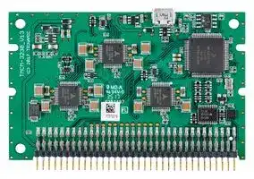
Illustrative purposes only

TMCM-3230-CANOPEN
Stepper Motor Driver, 2-Phase, 3-Axis, 1A, 12V - 24V DC Output, CANOpen Firmware
⚠️ Reference pricing provided. In case of supply shortages, we will connect you with our trusted procurement partners to ensure your project's continuity.
- Manufacturer: TRINAMIC / ANALOG DEVICES
- Product type: Stepper Motor Drives
- Supply Voltage Min:9V; Supply Voltage Max:28V; No. of Phases:Two Phase; Power Rating:-; Output Voltage Max:24V; Output Current:1A; Product Range:-; SVHC:No SVHC (27-Jun-2018)
- SVHC: No SVHC (04-Feb-2026)
- No. of Phases: Two Phase
- Product Range: TMCM StepRocker
- Output Current Max: 1A
- Supply Voltage Max: 28VDC
- Supply Voltage Min: 9VDC
- Control / Drive Type: 3-Axis Controller / Driver Module
| Delivery and price | |
|---|---|
| Units per pack | 1 |
| Price | 189.92 € |
| Current stock | 10+ |
| Lead time | 30 days |
Datasheet

**MODULE**

**Module for Stepper Motors**

## TMCM-3230 Hardware Manual

Hardware Version V1.30 | Document Revision V1.10 • 2017-NOV-02

**The TMCM-3230 is a compact and easy to use 3-axes stepper motor controller and driver unit for embedded applications. It offers CAN bus, UART and USB interfaces for communication and supports stand-alone operation, also. The TMCM-3230 features stealthChop™for absolute silent motor control, spreadCycle™for high speed stepper motor commutation, a fully integrated hardware motion controller with sixPoint™motion ramps, as well as stallGuard2™and coolStep™.**

## Features

- 3-axes stepper motor controller / driver

- Supply Voltage +12 to +24V DC (9V .. 28.5V max.)

- CAN, UART and USB interfaces

- TMCL or CANopen protocol

- Integrated **sixPoint™** ramp motion controller

- **stealthChop™** silent PWM mode

- **spreadCycle™** smart mixed decay

- **stallGuard2™** load detection

- **coolStep™** autom. current scaling

## Applications

- Laboratory Automation

- Manufacturing

- Semiconductor Handling

- Robotics

- Factory Automation

- Test & Measurement

- Life Science

- Biotechnology

- Liquid Handling

## Simplified Block Diagram

**==> picture [387 x 152] intentionally omitted <==**

**----- Start of picture text -----**<br>
TMCM-3230<br>DC<br>EEPROM 12..24V<br>DC<br>5V<br>I2C<br>er ernEeeens orasr== nree eeor se*= ee-™ a es | |<br>USB<br>s oO 3x I<br>TMC5130<br>CAN 8, !| itI, ||<br>µC SPI<br>|<br>UART (ARM) | +5V<br>8 +5V REF0L, REF0R<br>Inputs og | {|— | | |<br>i 8 ) ot | | |<br>Outputs<br>**----- End of picture text -----**<br>


> ©2017 TRINAMIC Motion Control GmbH & Co. KG, Hamburg, Germany Terms of delivery and rights to technical change reserved. Download newest version at: www.trinamic.com

Read entire documentation.

TMCM-3230 Hardware Manual • Hardware Version V1.30 | Document Revision V1.10 • 2017-NOV-02

2 / 22

## **Contents**

|**1**|**Features**|**Features**||**3**|
|---|---|---|---|---|
||1.1|General Features . . . . . . . . . .|. . . . . . . . . . . . . . . . . . . . . . . . . . . . . . . . . . .|3|
||1.2|TRINAMIC’s Unique Features<br>. . .|. . . . . . . . . . . . . . . . . . . . . . . . . . . . . . . . . . .|4|
|||1.2.1<br>stealthChop™. . . . . . . .|. . . . . . . . . . . . . . . . . . . . . . . . . . . . . . . . . . .|4|
|||1.2.2<br>spreadCycle™. . . . . . . .|. . . . . . . . . . . . . . . . . . . . . . . . . . . . . . . . . . .|4|
|||1.2.3<br>stallGuard2<br>. . . . . . . . .|. . . . . . . . . . . . . . . . . . . . . . . . . . . . . . . . . . .|4|
|||1.2.4<br>coolStep . . . . . . . . . . .|. . . . . . . . . . . . . . . . . . . . . . . . . . . . . . . . . . .|5|
|||1.2.5<br>sixPoint Motion Controller|. . . . . . . . . . . . . . . . . . . . . . . . . . . . . . . . . . .|5|
|**2**|**Order Codes**|||**7**|
|**3**|**Mechanical and Electrical Interfacing**|||**8**|
||3.1|TMCM-3230 Dimensions . . . . . .|. . . . . . . . . . . . . . . . . . . . . . . . . . . . . . . . . . .|8|
|**4**|**Connectors and LEDs**|||**9**|
||4.1|Main Connector . . . . . . . . . . .|. . . . . . . . . . . . . . . . . . . . . . . . . . . . . . . . . . .|9|
||4.2|USB Connector<br>. . . . . . . . . . .|. . . . . . . . . . . . . . . . . . . . . . . . . . . . . . . . . . .|10|
||4.3|CAN Connection . . . . . . . . . . .|. . . . . . . . . . . . . . . . . . . . . . . . . . . . . . . . . . .|11|
||4.4|LEDs. . . . . . . . . . . . . . . . . .|. . . . . . . . . . . . . . . . . . . . . . . . . . . . . . . . . . .|12|
|**5**|**Motor driver current**|||**13**|
|**6**|**Functional Description**|||**15**|
|**7**|**Operational Ratings and Characteristics**|||**16**|
||7.1|Absolute Maximum Ratings . . . .|. . . . . . . . . . . . . . . . . . . . . . . . . . . . . . . . . . .|16|
||7.2|Electrical Characteristics (Ambient Temperature 25° C) . . . . . . . . . . . . . . . . . . . . . . .||16|
||7.3|I/O Ratings (Ambient Temperature 25° C) . . . . . . . . . . . . . . . . . . . . . . . . . . . . . . .||16|
||7.4|Other Requirements . . . . . . . .|. . . . . . . . . . . . . . . . . . . . . . . . . . . . . . . . . . .|17|
|**8**|**Abbreviations used in this Manual**|||**17**|
|**9**|**Figures Index**|||**18**|
|**10 **|**Tables Index**|||**19**|
|**11 **|**Supplemental Directives**|||**20**|
||11.1|Producer Information<br>. . . . . . .|. . . . . . . . . . . . . . . . . . . . . . . . . . . . . . . . . . .|20|
||11.2|Copyright . . . . . . . . . . . . . . .|. . . . . . . . . . . . . . . . . . . . . . . . . . . . . . . . . . .|20|
||11.3|Trademark Designations and Symbols . . . . . . . . . . . . . . . . . . . . . . . . . . . . . . . . .||20|
||11.4|Target User . . . . . . . . . . . . . .|. . . . . . . . . . . . . . . . . . . . . . . . . . . . . . . . . . .|20|
||11.5|Disclaimer: Life Support Systems .|. . . . . . . . . . . . . . . . . . . . . . . . . . . . . . . . . . .|20|
||11.6|Disclaimer: Intended Use<br>. . . . .|. . . . . . . . . . . . . . . . . . . . . . . . . . . . . . . . . . .|20|
||11.7|Collateral Documents & Tools . . .|. . . . . . . . . . . . . . . . . . . . . . . . . . . . . . . . . . .|21|
|**12 **|**Revision History**|||**22**|
||12.1|Hardware Revision . . . . . . . . .|. . . . . . . . . . . . . . . . . . . . . . . . . . . . . . . . . . .|22|
||12.2|Document Revision . . . . . . . . .|. . . . . . . . . . . . . . . . . . . . . . . . . . . . . . . . . . .|22|


> ©2017 TRINAMIC Motion Control GmbH & Co. KG, Hamburg, Germany Terms of delivery and rights to technical change reserved. Download newest version at www.trinamic.com

TMCM-3230 Hardware Manual • Hardware Version V1.30 | Document Revision V1.10 • 2017-NOV-02

3 / 22

## **1 Features**

The TMCM-3230 is a compact three axes 2-phase stepper motor controller and driver module. It provides a complete motion control solution at a very small size for embedded applications. The board can be easily plugged into a customized baseboard offering a single 68pin connector.

Host communication is possible via the serial UART interface (e.g. using a standard RS232 or RS485 level shifter) or via CAN (CAN controller is already integrated on board). An additional USB interface (Micro-USB) may be used for firmware updates, download of TMCL programs or setting of parameters - either in system or stand-alone without any further connections.

The TMCM-3230 is supported by the intergated development environment TMCL-IDE v3.0. It supports stand-alone TMCL program execution (on-board EEPROM) and remote controlled operation. The TMCM-3230 has been designed with compatibily in mind with previous generation TMCM-343/TMCM303 modules - keeping similar mechanical and electrical characteristics (drop-in replacement for many applications) while offering advanced features.

## **1.1 General Features**

## **Main Characteristics**

- Supply Voltage +12V to +24V DC nom. (9V..28.5V abs. max.)

- 1A RMS phase current (approx. 1.4A peak phase current)

- Up to 256 micro steps per full step

- Permanent onboard parameter storage (EEPROM)

- Advanced sixPoint™ramp hardware motion controller (for each axis)

- Noiseless stealthChop™chopper mode for slow to medium velocities

- High performance spreadCycle™chopper mode

- High-precision sensorless load measurement with stallGuard2™

- Automatic current scaling algorithm coolStep™to save energy and keep your drive cool

## **I/Os**

- 8 general purpose inputs (0..5V) - either analog or digital

- 8 general purpose outputs (+5V level)

- L+R reference switch inputs (for all three axes)

- Shutdown input to power-on/-off drivers

- Alarm output

- Reset input

## **Communication Interfaces**

- Standard CAN Bus Interface for control and configuration

- UART interface supporting e.g. RS232, RS422 or RS485 with external transceiver

- SPI master interface

> ©2017 TRINAMIC Motion Control GmbH & Co. KG, Hamburg, Germany Terms of delivery and rights to technical change reserved. Download newest version at www.trinamic.com

TMCM-3230 Hardware Manual • Hardware Version V1.30 | Document Revision V1.10 • 2017-NOV-02

4 / 22

## **1.2 TRINAMIC’s Unique Features**

## **1.2.1 stealthChop™**

stealthChop is an extremely quiet mode of operation for low and medium velocities. It is based on a voltage mode PWM. During standstill and at low velocities, the motor is absolutely noiseless. Thus, stealthChop operated stepper motor applications are very suitable for indoor or home use. The motor operates absolutely free of vibration at low velocities. With stealthChop, the motor current is applied by driving a certain effective voltage into the coil, using a voltage mode PWM. There are no more configurations required except for the regulation of the PWM voltage to yield the motor target current.

_Figure 1: Motor coil sine wave current using stealthChop (measured with current probe)_

## **1.2.2 spreadCycle™**

The spreadCycle chopper is a high-precision, hysteresis-based, and simple to use chopper mode, which automatically determines the optimum length for the fast-decay phase. Several parameters are available to optimize the chopper to the application. spreadCycle offers optimal zero crossing performance compared to other current controlled chopper algorithms and thereby allows for highest smoothness. The true target current is powered into the motor coils.

_Figure 2: spreadCycle principle_

## **1.2.3 stallGuard2**

stallGuard2 is a high-precision sensorless load measurement using the back EMF of the motor coils. It can be used for stall detection as well as other uses at loads below those which stall the motor. The

> ©2017 TRINAMIC Motion Control GmbH & Co. KG, Hamburg, Germany Terms of delivery and rights to technical change reserved. Download newest version at www.trinamic.com

TMCM-3230 Hardware Manual • Hardware Version V1.30 | Document Revision V1.10 • 2017-NOV-02

5 / 22

stallGuard2 measurement value changes linearly over a wide range of load, velocity, and current settings. At maximum motor load, the value reaches zero or is near zero. This is the most energy-efficient point of operation for the motor.

**==> picture [387 x 159] intentionally omitted <==**

**----- Start of picture text -----**<br>
stallGuard2<br>Load [Nm]<br>Initial stallGuard2 (SG) value: 100%<br>Max. load<br>stallGuard2 (SG) value: 0<br>Maximum load reached.<br>Motor close to stall.<br>Motor stalls<br>**----- End of picture text -----**<br>


_Figure 3: stallGuard2 Load Measurement as a Function of Load_

## **1.2.4 coolStep**

coolStep is a load-adaptive automatic current scaling based on the load measurement via stallGuard2. coolStep adapts the required current to the load. Energy consumption can be reduced by as much as 75%. coolStep allows substantial energy savings, especially for motors which see varying loads or operate at a high duty cycle. Because a stepper motor application needs to work with a torque reserve of 30% to 50%, even a constant-load application allows significant energy savings because coolStep automatically enables torque reserve when required. Reducing power consumption keeps the system cooler, increases motor life, and allows for cost reduction.

**==> picture [325 x 155] intentionally omitted <==**

**----- Start of picture text -----**<br>
0,9<br>Efficiency with coolStep<br>0,8 Efficiency with 50v torque reserve<br>0,7<br>0,6<br>0,5<br>Efficiency<br>0,4<br>0,3<br>0,2<br>0,1<br>0<br>0 50 100 150 200 250 300 350<br>Velocity [RPM]<br>**----- End of picture text -----**<br>


_Figure 4: Energy Efficiency Example with coolStep_

## **1.2.5 sixPoint Motion Controller**

TRINAMIC’s sixPoint motion controller is a new type of ramp generator, which offers faster machine operation compared to the classical linear acceleration ramps. The sixPoint ramp generator allows adapting

> ©2017 TRINAMIC Motion Control GmbH & Co. KG, Hamburg, Germany Terms of delivery and rights to technical change reserved. Download newest version at www.trinamic.com

TMCM-3230 Hardware Manual • Hardware Version V1.30 | Document Revision V1.10 • 2017-NOV-02

6 / 22

the acceleration ramps to the torque curves of a stepper motor and uses two different acceleration settings each for the acceleration phase and for the deceleration phase

**==> picture [386 x 176] intentionally omitted <==**

_Figure 5: Typical motion profile with TRINAMIC’s sixPoint motion controller_

> ©2017 TRINAMIC Motion Control GmbH & Co. KG, Hamburg, Germany Terms of delivery and rights to technical change reserved. Download newest version at www.trinamic.com

TMCM-3230 Hardware Manual • Hardware Version V1.30 | Document Revision V1.10 • 2017-NOV-02

7 / 22

## **2 Order Codes**

|Order Code|Description|Size (LxWxH)|
|---|---|---|
|TMCM-3230-TMCL|3-axes stepper motor controller / driver<br>+24V / 1A RMS<br>TMCL frmware installed|80mm x 50mm x 6mm|
|TMCM-3230-CANopen|3-axes stepper motor controller / driver<br>+24V / 1A RMS<br>CANopen frmware installed|80mm x 50mm x 6mm|


_Table 1: Order Codes_

©2017 TRINAMIC Motion Control GmbH & Co. KG, Hamburg, Germany Terms of delivery and rights to technical change reserved. Download newest version at www.trinamic.com

TMCM-3230 Hardware Manual • Hardware Version V1.30 | Document Revision V1.10 • 2017-NOV-02

8 / 22

## **3 Mechanical and Electrical Interfacing**

## **3.1 TMCM-3230 Dimensions**

The dimensions of the controller/driver unit are approx. 80mm x 50mm. There are three mounting holes for M3 screws and two slots on each side for optional card holders.

**==> picture [479 x 245] intentionally omitted <==**

**----- Start of picture text -----**<br>
Horizontal<br>(80/50)<br>Connector:<br>i<br>(4/46) THCN=3290 20 7 cn | Wm tb oe <=<br>(76/46)<br>1) i VIDS, st See ef. os SS<br>lyn fe’Mil" 328Bi-iEOoeaf 5 200% AeAUR 9 ? R ohe) lee2CeemyIae©efOe eeeSHAE ett aeabaaentetS +)<br>(0/39.1) ctge}< OTNe no.(a ll WTSiy ' ne eyosON VG 4r gfP<br>(0/36.9) (2.2/38)<br>ROS 2001"). Sr =a | a 0 Npbeba Zz 325<br>2 TOT Pony Nees! HANTHEHITAY Soe oO; the & B%<br>eed ra C) Wh hie <a oe _' te ase<br>(0/24.4) (1.2/23.15)<br>(0/21.9) = “GS :20= Os SO of eoaet |p i:<br>=! tet “les es, HtHYHEAYRE, “S¢ me |<br>ye SOOO IDDNQAIOICO 4° RTT<br>m TERTECEROEie aaa fd go ys ge ds de faEELde’ CRfe  CECia ie a ieREte  RCEak aeTR TP RCEE REEtar G6<br>(4/4) co ‘lag Ga bad Gl sal ea eee reere, - rey Y [ i ; ; .1 4<br>oa a PPV UP PUPP P PEPE PEPE PEEP- " EEL7 EET Ea<br>(0/0) (10/0) HT Saeen (76/0) 4<br>68-Pin Connector 2<br>**----- End of picture text -----**<br>


_Figure 6: TMCM-3230 mechanical dimensions (all values in mm, (x/y))_

> ©2017 TRINAMIC Motion Control GmbH & Co. KG, Hamburg, Germany Terms of delivery and rights to technical change reserved. Download newest version at www.trinamic.com

TMCM-3230 Hardware Manual • Hardware Version V1.30 | Document Revision V1.10 • 2017-NOV-02

9 / 22

## **4 Connectors and LEDs**

## **4.1 Main Connector**

The TMCM-3230 has been designed as plug-in module. It offers one 68pin connector with 2mm pitch for connection of supply (driver and optional +5V digital supply), communication interfaces (CAN, UART - e.g. RS232, RS422 or RS485 with external transceiver), up-to eight digital outputs (0..+5V), up-to eight analog or digital inputs (0..+5V), reference switch inputs for all three axes (may be used as Step/Direction inputs) and motor driver outputs for three axes.

**==> picture [190 x 90] intentionally omitted <==**

**----- Start of picture text -----**<br>
2 68<br>1 67<br>-( OMDRTRUPTIRERERARRRRRERRRRRRERREE<br>TTT<br>Main Connector<br>2 4 6 8 10 64 66 68<br>Ooooo(jooo<br>OOO0O0 1 3 5 7 9 \O 63 Oo 65 67<br>| PCB XK<br>**----- End of picture text -----**<br>


_Figure 7: TMCM-3230 main connector_

|Main Connector Pin Assignment|Main Connector Pin Assignment|Main Connector Pin Assignment|Main Connector Pin Assignment|Main Connector Pin Assignment|Main Connector Pin Assignment|
|---|---|---|---|---|---|
|Pin|Direction|Description|Pin|Direction|Description|
|1|In|+5V DC digital supply in|2|In|GND|
|3|In|+5V DC digital supply in|4|In|GND|
|5|In|+12V..+24V driver supply in|6|In|GND|
|7|In|+12V..+24V driver supply in|8|In|GND|
|9|In|+12V..+24V driver supply in|10|In|GND|
|11|Out|SPI Select 0 (EtherCAT)|12|Out|SPI Clock (EtherCAT)|
|13|-|Reserved|14|In|SPI MISO (EtherCAT)|
|15|In|SPI IRQ (EtherCAT)|16|Out|SPI MOSI (EtherCAT)|
|17|In|Reset, active low|18|Out|Alarm|
|19|In|Motor 0 REFR / DIR|20|Out|Motor 0 A0|
|21|In|Motor 0 REFL / STEP|22|Out|Motor 0 A1|
|23|In|Motor 1 REFR / DIR|24|Out|Motor 0 B0|
|25|In|Motor 1 REFL / STEP|26|Out|Motor 0 B1|


©2017 TRINAMIC Motion Control GmbH & Co. KG, Hamburg, Germany Terms of delivery and rights to technical change reserved. Download newest version at www.trinamic.com

TMCM-3230 Hardware Manual • Hardware Version V1.30 | Document Revision V1.10 • 2017-NOV-02

10 / 22

|Pin|Direction|Description|Pin|Direction|Description|
|---|---|---|---|---|---|
|27|In|Motor 2 REFR / DIR|28|Out|Motor 1 A0|
|29|In|Motor 2 REFL / STEP|30|Out|Motor 1 A1|
|31|-|Reserved|32|Out|Motor 1 B0|
|33|-|Reserved|34|Out|Motor 1 B1|
|35|-|Reserved|36|Out|Motor 2 A0|
|37|-|Reserved|38|Out|Motor 2 A1|
|39|-|Reserved|40|Out|Motor 2 B0|
|41|-|Reserved|42|Out|Motor 2 B1|
|43|-|Reserved|44|In|Shutdown (2k2 pull-up to +5V)|
|45|In|General purpose input 0|46|Out|General purpose output 0|
|47|In|General purpose input 1|48|Out|General purpose output 1|
|49|In|General purpose input 2|50|Out|General purpose output 2|
|51|In|General purpose input 3|52|Out|General purpose output 3|
|53|In|General purpose input 4|54|Out|General purpose output 4|
|55|In|General purpose input 5|56|Out|General purpose output 5|
|57|In|General purpose input 6|58|Out|General purpose output 6|
|59|In|General purpose input 7|60|Out|General purpose output 7|
|61|In|GND|62|In|GND|
|63|-|Reserved|64|Out|RS485 Direction|
|65|In and Out|CAN-|66|In|UART_RxD|
|67|In and Out|CAN+|68|Out|UART_TxD|


_Table 2: Main Connector Pin Assignment_

## _**NOTICE**_

Do not plug-in or remove TMCM-3230 during operation! Voltage spikes and / or partly connected supply pins might lead to permanent damage of the module.

## **4.2 USB Connector**

The TMCM-3230 offers one Micro-USB connector. This connector is located at the upper end of the plug-in module. It has been integrated for quick and easy parameter setting and firmware udpates of the module - either in-system or even while the main connector is un-plugged. The USB device interface (Full-speed) supports USB bus powered operation. During this mode the processor and the on-board non-volatile memory (EEPROM) are powered and firmware updates, download of TMCL programs and parameter setting is possible without any further connection - apart from USB. In addition, UART communication, the SPI interface, all general purpose inputs and the dedicated Reset input are operational while all other connections - motor driver outputs, general purpose outputs, Shutdown input, Alarm output, the CAN interface and all REF / Step / Dir inputs are not operational.

In self powered mode when the TMCM-3230 is plugged into its mainboard and power via the 68pin connector is applied communication via USB is possible, also. In this configuration USB might be used as

> ©2017 TRINAMIC Motion Control GmbH & Co. KG, Hamburg, Germany Terms of delivery and rights to technical change reserved. Download newest version at www.trinamic.com

TMCM-3230 Hardware Manual • Hardware Version V1.30 | Document Revision V1.10 • 2017-NOV-02

11 / 22

an alternative to the other serial interfaces. Please note that the module might draw current via the USB connection in this mode, also.

**==> picture [53 x 7] intentionally omitted <==**

**----- Start of picture text -----**<br>
USB Connector<br>**----- End of picture text -----**<br>


_Figure 8: TMCM-3230 USB Connector_

## **4.3 CAN Connection**

For remote control and communication with a host system the TMCM-3230 provides a CAN bus interface with on-board CAN transceiver. For proper operation the following items should be taken into account when setting up a CAN network:

> **Bus Structure** The network topology should follow a bus structure as closely as possible. That is, the connection between each node and the bus itself should be as short as possible. Basically, it should be short compared to the length of the bus.

_Figure 9: CAN Bus Structure_

**Bus Termination** Especially for longer busses and/or multiple nodes connected to the bus and/or high communication speeds, the bus should be properly terminated at both ends. The TMCM-3230 does not integrate any termination resistor. Therefore, 120 Ohm termination resistors at both ends of the bus have to be added externally.

**Number of Nodes** The bus transceiver used on the TMCM-3230 (TJA1051) supports at least 100 nodes under optimum conditions. Practically achievable number of nodes per CAN bus highly depend on bus length (longer bus = less nodes) and communication speed (higher speed = less nodes).

> ©2017 TRINAMIC Motion Control GmbH & Co. KG, Hamburg, Germany Terms of delivery and rights to technical change reserved. Download newest version at www.trinamic.com

TMCM-3230 Hardware Manual • Hardware Version V1.30 | Document Revision V1.10 • 2017-NOV-02

12 / 22

## **4.4 LEDs**

The TMCM-3230 offers two LEDs: one green and one red LED. Both LEDs are connected to the processor. Function of the LEDs depends on the firmware version / type of firmware (e.g. TMCL / CANopen). See figure 10 for the LED location.

**==> picture [93 x 6] intentionally omitted <==**

**----- Start of picture text -----**<br>
Red LED Green LED<br>**----- End of picture text -----**<br>


_Figure 10: TMCM-3230 Location of LEDs_

|Status LEDs with TMCL Firmware|Status LEDs with TMCL Firmware|Status LEDs with TMCL Firmware|
|---|---|---|
|Green LED|Red LED|TMCL Firmware|
|Blinking|Off|Operational, firmware is running.|
|On|On|Bootloader / firmware update mode.|
|Off|Off|Power Off|


_Table 3: Status LEDs with TMCL Firmware_

> ©2017 TRINAMIC Motion Control GmbH & Co. KG, Hamburg, Germany Terms of delivery and rights to technical change reserved. Download newest version at www.trinamic.com

TMCM-3230 Hardware Manual • Hardware Version V1.30 | Document Revision V1.10 • 2017-NOV-02

13 / 22

## **5 Motor driver current**

The on-board stepper motor driver operates current controlled. The driver current may be programmed in software with 32 effective current scaling steps (CS) in hardware.

_Explanation of different columns in table below:_

> **Motor current** These are the values for TMCL axis parameter 6 (motor run current) and 7 (motor standby current). They are used to set the run / standby current **setting in** using the following TMCL commands: **software (TMCL)** SAP 6, 0, <value> // set run current SAP 7, 0, <value> // set standby current (read-out value with GAP instead of SAP. Please see separate TMCM-3230 firmware manual for further information)

> **Current scaling** This is the effective current scaling in hardware. 32 different scaling steps are available in hardware.

> **Motor current** Resulting motor current based on motor current setting. Motor current is listed as peak (sine peak) value (IPEAK) and RMS-value (IRMS). For stepper motors rated current is usually listed as IRMS value.

|**Motor**<br>**current**<br>**setting**<br>**in**<br>**soft-**<br>**ware (TMCL)**|**Current**<br>**scaling**<br>**step in hardware**<br>**(CS)**|**Motor**<br>**current**<br>**IPEAK[A]**|**Motor**<br>**current**<br>**IRMS[A]**|
|---|---|---|---|
|0..7|0|0.047|0.033|
|8..15|1|0.094|0,066|
|16..23|2|0.141|0.099|
|24..31|3|0.188|0.133|
|32..39|4|0.234|0.166|
|40..47|5|0.281|0.199|
|48..55|6|0.328|0.232|
|56..63|7|0.375|0.265|
|64..71|8|0.422|0.298|
|72..79|9|0.469|0.331|
|80..87|10|0.516|0.365|
|88..95|11|0.563|0.398|
|96..103|12|0.609|0.431|
|104..111|13|0.656|0.464|
|112..119|14|0.703|0.497|
|120..127|15|0.750|0.530|
|128..135|16|0.797|0.563|
|136..143|17|0.844|0.597|


©2017 TRINAMIC Motion Control GmbH & Co. KG, Hamburg, Germany Terms of delivery and rights to technical change reserved. Download newest version at www.trinamic.com

TMCM-3230 Hardware Manual • Hardware Version V1.30 | Document Revision V1.10 • 2017-NOV-02

14 / 22

|**Motor**<br>**current**<br>**setting**<br>**in**<br>**soft-**<br>**ware (TMCL)**|**Current**<br>**scaling**<br>**step in hardware**<br>**(CS)**|**Motor**<br>**current**<br>**IPEAK[A]**|**Motor**<br>**current**<br>**IRMS[A]**|
|---|---|---|---|
|144..151|18|0.891|0.630|
|152..159|19|0.938|0.663|
|160..167|20|0.984|0.696|
|168..175|21|1.031|0.729|
|176..183|22|1.078|0.762|
|184..191|23|1.125|0.795|
|192..199|24|1.172|0.829|
|200..207|25|1.219|0.862|
|208..215|26|1.266|0.895|
|216..223|27|1.313|0.928|
|224..231|28|1.359|0.961|
|232..239|29|1.406|0.994|
|240..247|30|1.453|1.028|
|248..255|31|1.500|1.061|


In addition to the settings in the table the motor current may be switched off completely (free-wheeling) using axis parameter 204 (see TMCM-3230 firmware manual).

> ©2017 TRINAMIC Motion Control GmbH & Co. KG, Hamburg, Germany Terms of delivery and rights to technical change reserved. Download newest version at www.trinamic.com

TMCM-3230 Hardware Manual • Hardware Version V1.30 | Document Revision V1.10 • 2017-NOV-02

15 / 22

## **6 Functional Description**

The TMCM-3230 contains the following main parts:

- 3x TMC5130 combined stepper motor controller and driver

- processor running the TMCL interpreter or the CANopen stack (depending on firmware version)

- non-volatile memory for parmater and TMCL program storage (EEPROM)

- Input and output level shifter / buffer

- USB interface (with micro-USB connector), CAN interface with on-board transceiver and UART interface supporting external RS232, RS422 or RS485 connections

- SPI master interface

**==> picture [339 x 240] intentionally omitted <==**

**----- Start of picture text -----**<br>
TMCM-3230<br>EEPROM TMC5130 Motor 0<br>I2C SPI +5V<br>+5V REF0L, REF0R<br>USB<br>CAN<br>UART µC TMC5130 Motor 1<br>8 (ARM)<br>Inputs<br>8 +5V<br>Outputs +5V REF1L, REF1R<br>SPI<br>SPI<br>Master<br>TMC5130 Motor 2<br>DC +5V<br>12..24V DC +5V REF2L, REF2R<br>5V<br>**----- End of picture text -----**<br>


_Figure 11: Typical application scenario_

> ©2017 TRINAMIC Motion Control GmbH & Co. KG, Hamburg, Germany Terms of delivery and rights to technical change reserved. Download newest version at www.trinamic.com

TMCM-3230 Hardware Manual • Hardware Version V1.30 | Document Revision V1.10 • 2017-NOV-02

16 / 22

## **7 Operational Ratings and Characteristics**

## **7.1 Absolute Maximum Ratings**

|Parameter|Min|Max|Unit|
|---|---|---|---|
|DC Power supply voltage for operation|9|28.5|V|
|+5V DC input (optional)|4.8|5.2|V|
|Motor coil current / sine wave**peak**||1.4|A|
|Continuous motor current (**RMS**)||1|A|
|Working / environmental temperature|-30*)|+40**)|° C|


_Table 5: Absolute Maximum Ratings_

> _*)limited by test equipment. Operation down to -40° C can be expected. Test included cold start at this temperature._

> _**) constant air flow or heat sink (e.g. mounted to the backside of the pcb (Attention: please make sure to isolate heatsink from pcb)) may be required. All components are specified for operation up-to at least +85° C_

_**NOTICE**_ Stresses above those listed under "Absolute Maximum Ratings" may cause permanent damage to the device. This is a stress rating only and functional operation of the device at those or any other conditions above those indicated in the operation listings of this specification is not implied. Exposure to maximum rating conditions for extended periods may affect device reliability.

## **7.2 Electrical Characteristics (Ambient Temperature 25° C)**

|Parameter|Symbol|Min|Typ|Max|Unit|
|---|---|---|---|---|---|
|DC Power supply voltage for operation|VDD|9|12..24|28|V|
|Motor coil current / sine wave**peak**(chop-<br>per regulated, adjustable in software)|ICOIL peak|0||1.4|A|
|Continuous motor current (**RMS**)|ICOIL RMS|0||1.0|A|
|Power supply current|IDD||_≪_ICOIL|1.4_∗_ICOIL|A|


_Table 6: Electrical Characteristics_

## **7.3 I/O Ratings (Ambient Temperature 25° C)**

|Parameter|Symbol|Min|Typ|Max|Unit|
|---|---|---|---|---|---|
|Input voltage for general purpose inputs|VIN|0|0..5|5.5|V|
|Output voltage for general purpose outputs|VOUT|0|0..5|5.5|V|


_Table 7: I/O Ratings_

> ©2017 TRINAMIC Motion Control GmbH & Co. KG, Hamburg, Germany Terms of delivery and rights to technical change reserved. Download newest version at www.trinamic.com

TMCM-3230 Hardware Manual • Hardware Version V1.30 | Document Revision V1.10 • 2017-NOV-02

17 / 22

## **7.4 Other Requirements**

|Specifcations|Description or Value|
|---|---|
|Cooling|Free air|
|Working environment|Avoid dust, water, oil mist and corrosive gases, no condensation, no frosting|
|Working temperature|tbd|


_Table 8: Other Requirements and Characteristics_

## **8 Abbreviations used in this Manual**

|Abbreviation|Description|
|---|---|
|CAN|Controller Area Network|
|COMM|Common Anode or common cathode|
|IDE|Integrated Development Environment|
|LED|Light Emmitting Diode|
|RMS|Root Mean Square value|
|TMCL|TRINAMIC Motion Control Language|
|TTL|Transistor Transistor Logic|
|UART|Universal Asynchronous Receiver Transmitter|
|USB|Universal Serial Bus|


_Table 9: Abbreviations used in this Manual_

> ©2017 TRINAMIC Motion Control GmbH & Co. KG, Hamburg, Germany Terms of delivery and rights to technical change reserved. Download newest version at www.trinamic.com

TMCM-3230 Hardware Manual • Hardware Version V1.30 | Document Revision V1.10 • 2017-NOV-02

18 / 22

## **9 Figures Index**

|1|Motor coil sine wave current using||6|TMCM-3230 mechanical dimensions||
|---|---|---|---|---|---|
||stealthChop (measured with current|||(all values in mm, (x/y)) . . . . . . . . .|8|
|2<br>3|probe). . . . . . . . . . . . . . . . . . .<br>spreadCycle principle . . . . . . . . . .<br>stallGuard2 Load Measurement as a|4<br>4|7<br>8|TMCM-3230 main connector<br>. . . . .<br>TMCM-3230 USB Connector . . . . . .|9<br>11|
||Function of Load<br>. . . . . . . . . . . .|5|9|CAN Bus Structure<br>. . . . . . . . . . .|11|
|4<br>5|Energy Efciency Example with coolStep<br>Typical motion profle with TRINAMIC’s|5|10|TMCM-3230 Location of LEDs . . . . .|12|
||sixPoint motion controller . . . . . . .|6|11|Typical application scenario . . . . . .|15|


> ©2017 TRINAMIC Motion Control GmbH & Co. KG, Hamburg, Germany Terms of delivery and rights to technical change reserved. Download newest version at www.trinamic.com

TMCM-3230 Hardware Manual • Hardware Version V1.30 | Document Revision V1.10 • 2017-NOV-02

19 / 22

## **10 Tables Index**

- 1 Order Codes . . . . . . . . . . . . . . . 7 7 I/O Ratings . . . . . . . . . . . . . . . . 16 2 Main Connector Pin Assignment . . . 10 8 Other Requirements and Characteristics 17 3 Status LEDs with TMCL Firmware . . . 12 9 Abbreviations used in this Manual . . 17 5 Absolute Maximum Ratings . . . . . . 16 10 Hardware Revision . . . . . . . . . . . 22 6 Electrical Characteristics . . . . . . . . 16 11 Document Revision . . . . . . . . . . . 22

> ©2017 TRINAMIC Motion Control GmbH & Co. KG, Hamburg, Germany Terms of delivery and rights to technical change reserved. Download newest version at www.trinamic.com

TMCM-3230 Hardware Manual • Hardware Version V1.30 | Document Revision V1.10 • 2017-NOV-02

20 / 22

## **11 Supplemental Directives**

## **11.1 Producer Information**

## **11.2 Copyright**

TRINAMIC owns the content of this user manual in its entirety, including but not limited to pictures, logos, trademarks, and resources. © Copyright 2017 TRINAMIC. All rights reserved. Electronically published by TRINAMIC, Germany.

Redistributions of source or derived format (for example, Portable Document Format or Hypertext Markup Language) must retain the above copyright notice, and the complete Datasheet User Manual documentation of this product including associated Application Notes; and a reference to other available product-related documentation.

## **11.3 Trademark Designations and Symbols**

Trademark designations and symbols used in this documentation indicate that a product or feature is owned and registered as trademark and/or patent either by TRINAMIC or by other manufacturers, whose products are used or referred to in combination with TRINAMIC’s products and TRINAMIC’s product documentation.

This Hardware Manual is a non-commercial publication that seeks to provide concise scientific and technical user information to the target user. Thus, trademark designations and symbols are only entered in the Short Spec of this document that introduces the product at a quick glance. The trademark designation /symbol is also entered when the product or feature name occurs for the first time in the document. All trademarks and brand names used are property of their respective owners.

## **11.4 Target User**

The documentation provided here, is for programmers and engineers only, who are equipped with the necessary skills and have been trained to work with this type of product.

The Target User knows how to responsibly make use of this product without causing harm to himself or others, and without causing damage to systems or devices, in which the user incorporates the product.

## **11.5 Disclaimer: Life Support Systems**

TRINAMIC Motion Control GmbH & Co. KG does not authorize or warrant any of its products for use in life support systems, without the specific written consent of TRINAMIC Motion Control GmbH & Co. KG.

Life support systems are equipment intended to support or sustain life, and whose failure to perform, when properly used in accordance with instructions provided, can be reasonably expected to result in personal injury or death.

Information given in this document is believed to be accurate and reliable. However, no responsibility is assumed for the consequences of its use nor for any infringement of patents or other rights of third parties which may result from its use. Specifications are subject to change without notice.

## **11.6 Disclaimer: Intended Use**

The data specified in this user manual is intended solely for the purpose of product description. No representations or warranties, either express or implied, of merchantability, fitness for a particular purpose

> ©2017 TRINAMIC Motion Control GmbH & Co. KG, Hamburg, Germany Terms of delivery and rights to technical change reserved. Download newest version at www.trinamic.com

TMCM-3230 Hardware Manual • Hardware Version V1.30 | Document Revision V1.10 • 2017-NOV-02

21 / 22

or of any other nature are made hereunder with respect to information/specification or the products to which information refers and no guarantee with respect to compliance to the intended use is given.

In particular, this also applies to the stated possible applications or areas of applications of the product. TRINAMIC products are not designed for and must not be used in connection with any applications where the failure of such products would reasonably be expected to result in significant personal injury or death (safety-Critical Applications) without TRINAMIC’s specific written consent.

TRINAMIC products are not designed nor intended for use in military or aerospace applications or environments or in automotive applications unless specifically designated for such use by TRINAMIC. TRINAMIC conveys no patent, copyright, mask work right or other trade mark right to this product. TRINAMIC assumes no liability for any patent and/or other trade mark rights of a third party resulting from processing or handling of the product and/or any other use of the product.

## **11.7 Collateral Documents & Tools**

This product documentation is related and/or associated with additional tool kits, firmware and other items, as provided on the product page at: www.trinamic.com.

> ©2017 TRINAMIC Motion Control GmbH & Co. KG, Hamburg, Germany Terms of delivery and rights to technical change reserved. Download newest version at www.trinamic.com

TMCM-3230 Hardware Manual • Hardware Version V1.30 | Document Revision V1.10 • 2017-NOV-02

22 / 22

## **12 Revision History**

## **12.1 Hardware Revision**

|Version|Date|Author|Description|
|---|---|---|---|
|1.00|2016-JUN-30|GE|Initial prototpyes.|
|1.10|2016-NOV-11|GE|Major redesign.|
|1.20|2107-FEB-28|GE|Minor corrections in order to improve compatibility with previous<br>generation TMCM-343 / TMCM-303|
|1.30|2017-APR-12|GE|Power supply bufer capacitors added and mounting holes for<br>heatsink removed. First series version.|


_Table 10: Hardware Revision_

## **12.2 Document Revision**

|Version|Date|Author|Description|
|---|---|---|---|
|0.90|2016-DEC-12|GE|Initial release.|
|0.91|2017-JUL-12|GE|New hardware version added. Infos for series version added.|
|0.92|2017-SEP-05|GE|Minimum driver supply voltage adapted to series version.|
|1.00|2017-OCT-10|OK|Product picture on frst page changed.|
|1.10|2017-NOV-02|GE|Size of module in order codes corrected|


_Table 11: Document Revision_

> ©2017 TRINAMIC Motion Control GmbH & Co. KG, Hamburg, Germany Terms of delivery and rights to technical change reserved. Download newest version at www.trinamic.com
Updated at April 29, 2026
About Novapart
Novapart is a B2B electronic component broker specialising in stock shortages and cost reduction. We source hard-to-find parts and identify compliant alternatives across a catalogue of 410,000+ components from 500+ manufacturers.
Learn more →Stock Shortage Specialist
When a component is unavailable, discontinued or has an unacceptable lead time, we tap into our network of vetted European and Asian distributors to source what you need — without compromising on quality or traceability.
Request a quote →Compliant Alternatives
We identify pin-to-pin, electrically equivalent substitutes that meet the same certifications (RoHS, AEC-Q100, REACH) as your original specification — validated against datasheets, not just part numbers. Often at a lower cost.
BOM Analysis service →