
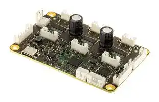


TMCM-3216-CANOPEN
Stepper Motor Controller, CANopen Firmware, 3-Axis Driver, 2A, 10 to 30 V, TMCM-3216 Series
- Manufacturer: ANALOG DEVICES
- Product type: Stepper Motor Drives
- SVHC: No SVHC (04-Feb-2026)
- No. of Phases: -
- Product Range: TMCM-3216 Series
- Output Current Max: 2A
- Supply Voltage Max: 30V
- Supply Voltage Min: 10V
- Control / Drive Type: 3-Axis Controller / Driver Module
| Delivery and price | |
|---|---|
| Units per pack | 1 |
| Price | 270.58 € |
| Current stock | 10+ |
| Lead time | 30 days |
**Data Sheet**

**TMCM-3216**

## 3-Axis Stepper Motor Controller/Driver Module

## **FEATURES**

- 3-Axis Stepper Motor Controller/Driver

- 24V (10V–30V) Supply Voltage Range

- 3x 1.5ARMS (2ARMS Peak) Motor Current

- Eight-Point Hardware Ramp Generator

- StealthChop™/SpreadCycle™

- REFL/REFR Reference Switch Inputs per Motor Axis

- A/B/N Encoder Input per Motor Axis

- 4x DIGITAL_IN/OUT, 24V Push-Pull or High-Side

- 2 ANALOG_IN, 0V–10V

- RS485/CAN/USB Interfaces

- 85mm x 55mm (Credit-Card Size)

- Automatic Board Address Assignment at Power-Up (Optional)

- TMCL, CANopen

## **APPLICATIONS**

## **GENERAL DESCRIPTION**

The TMCM-3216 is a compact, 3-axis bipolar stepper motor controller and standalone driver board. It supports up to three bipolar stepper motors with up to 2ARMS motor coil current and offers single-supply operation with typical 24VDC (10V–30V range).

There are separate reference/stop switches and incremental A/B/N encoder inputs per motor axis. In addition, the module offers four programmable digital inputs and outputs that are configurable as push-pull or high-side outputs. Two analog inputs support 0V– 10V signals.

A USB interface is available for configuration and updates. The RS485 and CAN bus interfaces can be used for in-system communication and daisy-chaining boards to simplify wiring through bus connectors at each end of the board.

- Industrial Automation

- Laboratory Automation

- Medical Devices

## **SIMPLIFIED APPLICATION DIAGRAM**

**==> picture [504 x 151] intentionally omitted <==**

**----- Start of picture text -----**<br>
STEP- STEP- STEP- STEP- STEP- STEP- STEP- STEP- STEP-<br>PER PER PER PER PER PER PER PER PER<br>AHH MOTOR MOTOR MOTOR B60 MOTOR MOTOR MOTOR - BOA MOTOR MOTOR MOTOR<br>RS485CANOR RS485CANOR RS485CANOR<br>(OPTIONAL SEPARATE CONTROLLER)<br>85mm WIRE FOR AUTOMATIC BOARD ADDRESS ASSIGNMENT AT POWER-UP<br>a —ie<br>WIRE FOR GLOBAL ERROR/EVENT NOTIFICATION 001<br>**----- End of picture text -----**<br>


_**Figure 1. Multiaxis Application Example**_

19-101961; Rev 0; 12/24

DOCUMENT FEEDBACK **TECHNICAL SUPPORT** Tel: 781.329.4700 | ©2024 Analog Devices, Inc. All rights reserved.

DOCUMENT FEEDBACK

One Analog Way, Wilmington, MA 01887-2356, U.S.A.

**TMCM-3216**

**Data Sheet**

**REVISION HISTORY 12/2024 - Rev. 0: Release for Market Intro**

Rev 0 2 of 17

**analog.com**

**TMCM-3216**

**Data Sheet**

## **SPECIFICATIONS**

**Table 1. Electrical Characteristics**

|**SPECIFICATIONS**<br>**Table 1. Electrical Characteristics**||||||||
|---|---|---|---|---|---|---|---|
|**PARAMETER**|**SYMBOL**|**CONDITIONS**|**COMMENTS**|**MIN**|**TYP**|**MAX**|**UNITS**|
|Supply Input Voltage|VSUPPLY|||10|24|30|V|
|Supply Input Current|ISUPPLY||||<< 3x<br>IMOTOR|3x<br>IMOTOR_FS<br>+<br>Digital<br>I/O|A|
|Motor Current (RMS)|IMOTOR||||1.5|2|ARMS|
|Motor Coil Current Sine Wave<br>Peak|IMOTOR_FS|||||2.8|A|
|Environmental Temperature at<br>Rated Motor Current (3x 1.5A<br>RMS), No Forced Cooling|TENV|||-40||+40|°C|
|Output Voltage for +5V|V+5V|||4.5||5.5|V|
|Output Current for +5V|I+5V||All +5V<br>output pins<br>together|||400|mA|
|Reference Switch REFL/R Input<br>Voltage|VREFL/R||Type 1/3<br>Digital Input|||30|V|
|Low-Level Reference Switch<br>REFL/R Input Voltage|VREFL/R_L||Type 1/3<br>Digital Input|||8|V|
|High-Level Reference Switch<br>REFL/R Input Voltage|VREFL/R_H||Type 1/3<br>Digital Input|10|||V|
|A/B/N Encoder Signal Input<br>Voltage|VENC||Internal 47kΩ<br>pull-up<br>resistor to<br>+5V|0||+5.5|V|
|Low-Level A/B/N Encoder Signal<br>Input Voltage|VENC_L|||||0.8|V|
|High-Level A/B/N Encoder Signal<br>Input Voltage|VENC_H|||2|||V|
|Digital I/O Output Current for<br>High-Side Switch Configuration<br>(HS)|IDIGITAL_HS||||175||mA|
|Digital I/O Output Current for<br>Push-Pull Configuration (PP)|IDIGITAL_PP||||200||mA|
|Digital I/O Input Voltage Range for<br>Input Configuration|VDIGITAL||Type 1/3<br>Digital Input|||VSUPPLY|V|


Rev 0 3 of 17

**analog.com**

**TMCM-3216**

**Data Sheet**

|**PARAMETER**|**SYMBOL**|**CONDITIONS**|**COMMENTS**|**MIN**|**TYP**|**MAX**|**UNITS**|
|---|---|---|---|---|---|---|---|
|Low-Level Digital I/O Input<br>Voltage for Input Configuration|VDIGITAL_L||Type 1/3<br>Digital Input|||6.7|V|
|High-Level Digital I/O Input<br>Voltage for Input Configuration|VDIGITAL_H||Type 1/3<br>Digital Input|8|||V|
|Analog Input Voltage Range|VANALOG||||0–10|30|V|
|EVENT Output Voltage Range|VEVENT||Internal 47kΩ<br>pull-up<br>resistor to<br>+5V||0–5|30|V|
|Event Output Sink Current|IEVENT|||||20|mA|
|ADDR_OUT Output Voltage Range|VADDR_OUT||Internal 47kΩ<br>pull-up<br>resistor to<br>+5V||0–5|30|V|
|ADDR_IN Input Voltage Range|VADDR_IN||||0–5|30|V|


## **Table 2. Thermal Characteristics**

|Test Setup|Lay the TMCM-3216 flat on the test bench. Natural air convection/no forced cooling at<br>room temperature (25°C). Three connected stepper motors move slowly throughout the<br>test.|
|---|---|
|Motor Current|3x 1.5ARMS/2Apeak|
|SupplyVoltage|24V|
|Thermal Image<br>Taken after a 30-<br>Minute Test Period|002<br>0.0A<br>C<br>104<br>(63.7<br>19.1<br>-<br>500m<br>-<br>“=<br>17<br>E95<br>A|
|Hot Spot|104°C is the maximum temperature at a 25°C environmental temperature.|
|Test result|The board reaches its maximum temperature at the driver stage for motor axis 1. The<br>maximum temperature is still well below the absolute maximum temperature specified<br>for the driver ICs.|


Rev 0 4 of 17

**analog.com**

**TMCM-3216**

**Data Sheet**

## **ABSOLUTE MAXIMUM RATINGS**

TA = 25°C, unless otherwise specified.

## **Table 3. Absolute Maximum Ratings**

|**PARAMETER**|**RATING**|
|---|---|
|Supply Input Voltage|-0.3V to +33V|
|Reference Switch REFL/R Input<br>Voltage|-40V to +40V|
|Digital I/O Input Voltage Range<br>for Input Configuration|-1V to VSUPPLY+ 0.3V|
|Analog Input Voltage Range|-0.3V to +40V|
|EVENT Output Voltage Range|-0.3V to +36V|
|ADDR_OUT Output Voltage<br>Range|-0.3V to +36V|
|ADDR_IN Input Voltage Range|-0.3V to +36V|


Stresses beyond those listed under Absolute Maximum Ratings may cause permanent damage to the device. These are stress ratings only, functional operation of the product at these or any other conditions above those indicated in the operational section of this specification is not implied. Operation beyond the maximum operating conditions for extended periods may affect product reliability.

## **Electrostatic Discharge (ESD)**

## **ESD Caution**

**ESD (electrostatic discharge) sensitive device.** Charged devices and circuit boards can discharge without detection. Although this product features patented or proprietary protection circuitry, damage may occur on devices subjected to high energy ESD. Therefore, proper ESD precautions should be taken to avoid performance degradation or loss of functionality.

## **Notes on Security**

The TMCM-3216 comes without enclosure or additional protection. It is intended for embedded motion control—to be integrated into customer system/machine with stepper motors, I/Os, and communication links connected internally according to application requirements. The customer is responsible for protecting the TMCM-3216 sufficiently inside the system/machine against direct access by the end user.

Rev 0 5 of 17

**analog.com**

**TMCM-3216**

**Data Sheet**

## **PIN CONFIGURATIONS AND FUNCTION DESCRIPTIONS**

## **Overview**

**==> picture [427 x 562] intentionally omitted <==**

**----- Start of picture text -----**<br>
|||||||||||||||
|---|---|---|---|---|---|---|---|---|---|---|---|---|---|
|MOTOR|MOTOR|MOTOR|
|AXIS 0|AXIS 1|AXIS 2|
|ny|1|»|4|Cart|peory|1|4|mn|moe|1|a|4|7|
|8|
|POWER|»O|2|.|REFERENCE|
|SUPPLY|A/B/N|A/B/N|A/B/N|SWITCHES|
|1|ENCODER|ENCODER|ENCODER|
|AXIS 0|||AXIS 1|ee|i|i|AXIS 2|aC)|
|1|5|1|5|1|5|
|8|8|
|Ox|oe)|eo=uze|ome):|we|
|COMMUNICATION|
|COMMUNICATION|OUT|
|IN1|=|oe|aeae|TT)|iE|“tttne|;}|1|
|3|1|3|1|
|OF|Salada|O-CO—-(Yee|
|USB|ANALOG IN|DIGITAL I/O|
|Figure 2.|TMCM-3216 Connectors|
|Table 4.|Connector Types and Mating Connectors|
|Connector|Connector Type|Mating Connector Type|
|Power Supply|JST B2P-VH (JST VH series, 2 pins,|Connector housing: JST VHR-2N|
|3.96mm pitch)|Contacts: JST SVH-21T-P1.1|
|Wire: 0.83mm|[2]|, AWG 18|
|Motor Axis 0-2|JST B4B-PH-K-S|Connector housing JST: PHR-4|
|(JST PH series, 4 pins, 2mm pitch)|Contacts JST: SPH-002T-P0.5S|
|Wire: 0.22mm|[2]|, AWG 24|
|Reference Switches|JST B8B-PH-K-S|Connector housing JST: PHR-8|
|(JST PH series, 8 pins, 2mm pitch)|Contacts JST: SPH-002T-P0.5S|
|Wire: 0.22mm|[2]|, AWG 24|
|A/B/N Encoder Axis 0-2|JST B5B-PH-K-S|Connector housing JST: PHR-5|
|(JST PH series, 5 pins, 2mm pitch)|Contacts JST: SPH-002T-P0.5S|
|Wire: 0.22mm|[2]|, AWG 24|
|Communication In|JST B8B-PH-K-S|Connector housing JST: PHR-8|
|(JST PH series, 8 pins, 2mm pitch)|Contacts JST: SPH-002T-P0.5S|
|Wire: 0.22mm|[2]|, AWG 24|
|Communication Out|JST B8B-PH-K-S|Connector housing JST: PHR-8|
|(JST PH series, 8 pins, 2mm pitch)|Contacts JST: SPH-002T-P0.5S|
|Wire: 0.22mm|[2]|, AWG 24|
|Digital I/O|JST B5B-PH-K-S|Connector housing JST: PHR-5|
|(JST PH series, 5 pins, 2mm pitch)|Contacts JST: SPH-002T-P0.5S|
|Wire: 0.22mm|[2]|, AWG 24|
|Analog In|JST B3B-PH-K-S|Connector housing JST: PHR-3|
|(JST PH series, 3 pins, 2mm pitch)|Contacts JST: SPH-002T-P0.5S|
|Wire: 0.22mm|[2]|, AWG 24|
|USB|USB-C|USB-C|

**----- End of picture text -----**<br>


**Table 4. Connector Types and Mating Connectors**

Rev 0 6 of 17

**analog.com**

**TMCM-3216**

**Data Sheet**

## **Power-Supply Connector**

**Table 5. Pin Descriptions**

|**Table 5.**|**Pin Descriptions**||||
|---|---|---|---|---|
|**PIN**|**NAME**|**DESCRIPTION**|**REF**<br>**SUPPLY**|**TYPE**|
|1|GND|Common-Supply GND|||
|2|VSUPPLY|Main Supply Input||IN|


## **Motor Axis 0-2 Connector**

**Table 6. Pin Descriptions**

|**Table 6.**|**Pin Descriptions**||||
|---|---|---|---|---|
|**PIN**|**NAME**|**DESCRIPTION**|**REF**<br>**SUPPLY**|**TYPE**|
|1|A2|Pin 2 of Motor Coil A|VSUPPLY|OUT|
|2|A1|Pin 1 of Motor Coil A|VSUPPLY|OUT|
|3|B2|Pin 2 of Motor coil B|VSUPPLY|OUT|
|4|B1|Pin 1 of Motor Coil B|VSUPPLY|OUT|


## **Reference Switches Connector**

**Table 7. Pin Descriptions**

|**PIN**|**NAME**|**DESCRIPTION**|**REF**<br>**SUPPLY**|**TYPE**|
|---|---|---|---|---|
|1|GND|Common-Supply GND|||
|2|VSUPPLY|VSUPPLYSupply Path through Output<br>**Note:**Do not use thispin as apower supplyinput for the module.|VSUPPLY|OUT|
|3|REFR0|Axis 0 Reference Switch Input Right<br>(24V industrial type 1/3 digital input)|VSUPPLY|IN|
|4|REFL0|Axis 0 Reference Switch Input Left<br>(24V industrial type1/3 digital input)|VSUPPLY|IN|
|5|REFR1|Axis 1 Reference Switch Input Right<br>(24V industrial type1/3 digital input)|VSUPPLY|IN|
|6|REFL1|Axis 1 Reference Switch Input Left<br>(24V industrial type 1/3 digital input)|VSUPPLY|IN|
|7|REFR2|Axis 2 Reference Switch Input Right<br>(24V industrial type 1/3 digital input)|VSUPPLY|IN|
|8|REFL2|Axis 2 Reference Switch Input Left<br>(24V industrial type 1/3 digital input)|VSUPPLY|IN|


Rev 0 7 of 17

**analog.com**

**TMCM-3216**

**Data Sheet**

## **A/B/N Encoder Axis 0-2 Connector**

**Table 8. Pin Descriptions**

|**PIN**|**NAME**|**DESCRIPTION**|**REF**<br>**SUPPLY**|**TYPE**|
|---|---|---|---|---|
|1|GND|Common-Supply GND|||
|2|+5V|+5V Supply Output||OUT|
|3|ENC_A|Encoder A-Channel Input (internal 47kΩ pull-up resistor to +5V)|+5V|IN|
|4|ENC_B|Encoder B-Channel Input (internal 47kΩ pull-up resistor to +5V)|+5V|IN|
|5|ENC_N|Encoder N-Channel Input (internal 47kΩ pull-up resistor to +5V)|+5V|IN|


## **Communication-In Connector**

**Table 9. Pin Descriptions**

|**PIN**|**NAME**|**DESCRIPTION**|**REF**<br>**SUPPLY**|**TYPE**|
|---|---|---|---|---|
|1|GND|Common-Supply GND|||
|2|CAN_H|CAN Interface, Differential Signaling (Noninverting)<br>(Connected to communication-out connector/pass-through)||IN/OUT|
|3|CAN_L|CAN Interface, Differential Signaling (Inverting)<br>(Connected to communication-out connector/pass-through)||IN/OUT|
|4|RS485_A|RS485 Interface, Differential Signaling (Noninverting)<br>(Connected to communication-out connector/pass-through)||IN/OUT|
|5|RS485_B|RS485 Interface, Differential Signaling (Inverting)<br>(Connected to communication-out connector/pass-through)||IN/OUT|
|6|EVENT|Event Input and Output<br>(Open drain with an internal 47kΩ pull-up resistor to +5V; connected to<br>communication-out connector/pass-through)|VSUPPLY|IN/OUT|
|7|ADDR_IN|Input Signal for Automatic Board Address Assignment|VSUPPLY|IN|
|8|GND|Common-Supply GND|||


Rev 0 8 of 17

**analog.com**

**TMCM-3216**

**Data Sheet**

## **Communication-Out Connector**

**Table 10.Pin Descriptions**

|**PIN**|**NAME**|**DESCRIPTION**|**REF**<br>**SUPPLY**|**TYPE**|
|---|---|---|---|---|
|1|GND|Common-Supply GND|||
|2|CAN_H|CAN Interface, Differential Signaling (Noninverting)<br>(Connected to communication-in connector/pass-through)||IN/OUT|
|3|CAN_L|CAN Interface, Differential Signaling (Inverting)<br>(Connected to communication-in connector/pass-through)||IN/OUT|
|4|RS485_A|RS485 Interface, Differential Signaling (Noninverting)<br>(Connected to communication-in connector/pass-through)||IN/OUT|
|5|RS485_B|RS485 Interface, Differential Signaling (Inverting)<br>(Connected to communication-in connector/pass-through)||IN/OUT|
|6|EVENT|Event Input and Output<br>(Open drain with an internal 47kΩ pull-up resistor to +5V; connected to<br>communication-in connector/pass-through)|VSUPPLY|IN/OUT|
|7|ADDR_OUT|Output Signal<br>(Open drain with an internal 47kΩ pull-up resistor to +5V for automatic<br>board address assignment)|VSUPPLY|OUT|
|8|GND|Common-supply GND|||


## **Digital I/O Connector**

**Table 11.Pin Descriptions**

|**PIN**|**NAME**|**DESCRIPTION**|**REF**<br>**SUPPLY**|**TYPE**|
|---|---|---|---|---|
|1|GND|Common-Supply GND|||
|2|DIO0|General-Purpose Digital Input 0/Output 0<br>Digital input: 24V industrial type 1/3<br>Digital output: High-side switch orpush-pull driver|VSUPPLY|IN/OUT|
|3|DIO1|General-Purpose Digital Input 1/Output 1<br>Digital input: 24V industrial type 1/3<br>Digital output: High-side switch orpush-pull driver|VSUPPLY|IN/OUT|
|4|DIO2|General-Purpose Digital Input 2/Output 2<br>Digital input: 24V industrial type 1/3<br>Digital output: High-side switch orpush-pull driver|VSUPPLY|IN/OUT|
|5|DIO3|General-Purpose Digital Input 3/Output 3<br>Digital input: 24V industrial type 1/3<br>Digital output: High-side switch orpush-pull driver|VSUPPLY|IN/OUT|


Rev 0 9 of 17

**analog.com**

**TMCM-3216**

**Data Sheet**

## **Analog-In Connector**

**Table 12.Pin Descriptions**

|**PIN**|**NAME**|**DESCRIPTION**|**REF**<br>**SUPPLY**|**TYPE**|
|---|---|---|---|---|
|1|GND|Common-Supply GND|||
|2|AIN1|General-Purpose Analog Input 1 (0V–10V)||IN|
|3|AIN0|General-Purpose Analog Input 0 (0V–10V)||IN|


Rev 0 10 of 17

**analog.com**

**TMCM-3216**

**Data Sheet**

## **DETAILED DESCRIPTION**

The TMCM-3216 is a highly-integrated, 3-axis stepper motor controller/driver module. It can be controlled through CAN, RS485, or USB serial interfaces.

The three stepper drivers support up to 2ARMS motor current and up to 256 microsteps per full step. Select either SpreadCycle chopper algorithm for highly-dynamic motor control or StealthChop2 chopper for silent motor operation. StallGuard2 or StallGuard4 can be used for sensorless load estimation. As an alternative, an incremental A/B/N encoder for step loss/deviation detection under all operating conditions is supported for all three axes. There are separate reference/stop switch inputs for each direction and motor.

For each axis, an eight-point motion ramp generator built into the hardware is available to support independent position movements and velocity control with on-the-fly changes.

An integrated Arm® M4 microcontroller provides CAN, RS485, and USB interfaces and connects to the three integrated stepper motor controllers and drivers. It supports overall system control, initialization, initiation, and synchronization of motor movements and communication protocol handling. There are two pre-loaded firmware versions: TMCL and CANopen.

The TMCL version of TMCM-3216 comes with the PC-based software development environment TMCL-IDE for the Trinamic Motion Control Language (TMCL). Using predefined TMCL high-level commands, such as move to position, a rapid and fast development of motion control applications is guaranteed. Communication traffic is kept low since all time critical operations, such as ramp calculations, are performed on board. Full remote control of the device with feedback is possible. The firmware of the module can be updated through any of the serial interfaces.

**==> picture [377 x 286] intentionally omitted <==**

**----- Start of picture text -----**<br>
USB/VBUS TMCM-3216<br>DC +5V +3V3<br>VSUPPLY DC LDO<br>STEPPER<br>CONTROLLER STEPPER<br>AND DRIVER MOTOR<br>RS485 TRANSCEIVER AXIS 0 AXIS 0<br>LS ENC_A/B/N<br>CAN TRANSCEIVER<br>SPI LS REFL0/REFR0<br>USB<br>VSUPPLY<br>VSUPPLY CONTROLLERSTEPPER STEPPER<br>VSUPPLY AND DRIVER MOTOR<br>MCU AXIS 1 AXIS 1<br>4× DIGITAL I/O<br>DIO0/1/2/3 (PP/HS) LS ENC_A/B/N<br>AIN0/1 LS LS REFL1/REFR1<br>LS VSUPPLY<br>STEPPER<br>EVENT DIGITAL OUT CONTROLLER STEPPER<br>ADDR_OUT (OD) AND DRIVERAXIS 2 MOTORAXIS 2<br>ADDR_IN LS I2C LS ENC_A/B/N<br>EEPROM<br>LS REFL2/REFR2<br>004<br>**----- End of picture text -----**<br>


_**Figure 3. TMCM-3216 Block Diagram**_

Rev 0 11 of 17

**analog.com**

**TMCM-3216**

**Data Sheet**

## **RS485**

For remote control and communication with a host system, the TMCM-3216 provides a 2-wire RS485 bus interface. For proper operation, consider the following items when setting up an RS485 network:

- **Bus Structure:** The network topology needs to follow a bus structure as closely as possible. The TMCM3216 supports this structure by providing communication connectors at both ends of the board that pass through the RS485 differential signals with a comparatively short stub connected to the on-board RS485 transceiver.

- **Bus Termination:** For longer busses and/or multiple nodes connected to the bus and/or high communication speeds, properly terminate the bus at both ends. The TMCM-3216 does not integrate any termination resistor. Therefore, externally add 120Ω termination resistors at both ends of the bus.

- **Number of Nodes:** The RS485 electrical interface standard (EIA-485) allows up to 32 nodes to be connected to a single bus. Usually, it is not expected to get reliable communication with a high number of nodes connected to one bus and maximum supported communication speed at the same time. Instead, a compromise must be made among bus cable length, communication speed, and number of nodes.

- **Communication Speed:** Factory default is 9.6kbps.

- **No Floating Bus Lines:** Avoid floating bus lines when neither the host/controller nor one of the peripheral devices along the bus line is transmitting data (all bus nodes are switched to receive mode). Floating bus lines can lead to communication errors. To ensure valid signals on the bus, it is recommended to use a resistor network connecting both bus lines to well-defined logic levels.

There are two recommendations. The first recommendation is to add a resistor (bias) network on one side of the bus only with a 120Ω termination resistor at both ends. See Figure 4.

**==> picture [450 x 128] intentionally omitted <==**

**----- Start of picture text -----**<br>
+5V<br>PULL-UP<br>(680Ω)<br>TERMINATION TMCM-3216 TMCM-3216 RS485+/RS485A<br>RESISTOR TERMINATION<br>(120Ω) RESISTOR<br>RS485–/RS485B (120Ω)<br>PULL-DOWN<br>(680Ω)<br>005<br>**----- End of picture text -----**<br>


_**Figure 4. Bus Lines with a Resistor (Bias) Network on One Side Only**_

Rev 0 12 of 17

**analog.com**

**TMCM-3216**

**Data Sheet**

The second recommendation is to add a resistor (bias) network at both ends of the bus, which is often referred to as Profibus™ termination. See Figure 5.

**==> picture [440 x 125] intentionally omitted <==**

**----- Start of picture text -----**<br>
+5V +5V<br>PULL-UP PULL-UP<br>(390Ω) (390Ω)<br>TMCM-3216 TMCM-3216 RS485+/RS485A<br>TERMINATION TERMINATION<br>RESISTOR RESISTOR<br>(220Ω) RS485–/RS485B (220Ω)<br>PULL-DOWN PULL-DOWN<br>(390Ω) (390Ω)<br>006<br>**----- End of picture text -----**<br>


_**Figure 5. Bus Lines with a Resistor (Bias) Network at Both Ends**_

## **CAN**

For remote control and communication with a host system, the TMCM-3216 also provides a CAN bus interface. For proper operation, consider the following items when setting up a CAN network:

- **Bus Structure:** The network topology needs to follow a bus structure as closely as possible. The TMCM3216 supports this structure by providing communication connectors at both ends of the board that pass through the CAN differential signals with a comparatively short stub connected to the on-board CAN transceiver.

- **Bus Termination:** For longer busses and/or multiple nodes connected to the bus and/or high communication speeds, properly terminate the bus at both ends. The TMCM-3216 does not integrate any termination resistor. Therefore, add external 120Ω termination resistors at both ends of the bus.

- **Number of Nodes:** The practically achievable number of nodes per CAN bus highly depends on bus length (longer bus → less nodes) and communication speed (higher speed → less nodes).

- **Communication Speed:** Factory default is 1Mbps.

## **USB**

For remote control and communication with a host system, the TMCM-3216 provides a USB interface (USB-C connector). As soon as a USB host is connected, the module accepts commands through USB. The TMCM-3216 supports self-powered USB operation (when an external power is supplied through the power supply connector) and USB bus-powered operation (with no external power supply through power-supply connector).

During USB bus-powered operation, only the core digital parts are operational (e.g., the microcontroller and the EEPROM). Motor movements are not possible. This mode has been implemented to enable configuration/ parameter setting/readout, firmware updates, etc. simply by connecting a USB cable between the module and a host PC. No additional cabling or external devices are required in that case.

Note that the module might draw current from the USB +5V bus supply even in USB self-powered operation, depending on the voltage level of this supply.

Rev 0 13 of 17

**analog.com**

**TMCM-3216**

**Data Sheet**

The USB interface can be used for configuration/firmware updates, initial tests, and service. For in-system communication, it is recommended to rely on the more robust RS485 or CAN bus interfaces.

## **On-Board LEDs**

The board offers two LEDs to indicate board status, labeled **Error** and **Run** . The LEDs function depends on the firmware version. With TMCL firmware, the green **Run** LED slowly flashes during operation, and the red **Error** LED does not illuminate. Refer to the TMCM-3216 TMCL firmware manual for additional information. When there is no valid firmware programmed into the board or during firmware update, the red and green LEDs remain illuminated.

Additionally, there are four green LEDs to indicate the status of the DIO0/1/2/3 digital inputs and outputs at the digital I/O connector. The LEDs indicate an active (high) state of the digital outputs or inputs.

**==> picture [188 x 96] intentionally omitted <==**

**----- Start of picture text -----**<br>
ERROR DIO2 DIO1<br>STATUS STATUS<br>RUN<br>DIO3 DIO0<br>: STATUS STATUS<br>: Pf ao ®<br>007<br>**----- End of picture text -----**<br>


_**Figure 6. On-Board LEDs**_

## **Reset to Factory Defaults**

It is possible to reset all the TMCM-3216 settings in the firmware to factory defaults without establishing a working communication connection. This approach may be helpful in case communication parameters of the preferred interface are accidentally set to unknown values or get lost during evaluation/prototype setup.

For this reset procedure, two test pads on the bottom side of the module must be shorted (electrically connected with each other) at power-up. Use the following procedure:

1. Switch off the power supply. **Optional:** Disconnect the USB cable, if applicable.

2. Short the pads on the bottom of the PCB. See _Figure 7_ .

3. Switch on the power supply again. **Optional:** Connect the USB cable again, if applicable.

4. Wait until the on-board red ( **Error** ) and green ( **Run** ) LEDs start flashing fast. **Note:** This may take several seconds.

5. Switch off the power supply. **Optional:** Disconnect the USB cable, if applicable.

6. Remove the short between pads.

Rev 0 14 of 17

**analog.com**

**TMCM-3216**

**Data Sheet**

7. After switching on the power supply again (or optionally connecting the USB cable again, if applicable), all permanent settings are restored to factory defaults.

**==> picture [181 x 59] intentionally omitted <==**

**----- Start of picture text -----**<br>
SHORT THESE<br>TWO PADS O° r i) . Hicnt A<br>e oo<br>e @<br>°® =<br>, DEVICES i<br>RoHS Cyamigs eo 008<br>**----- End of picture text -----**<br>


_**Figure 7. PCB Bottom View—Reset to Factory Defaults**_

## **OUTLINE DIMENSIONS**

The board with the controller/driver electronics measures at 85mm x 55mm overall and offers four mounting holes for M3 screws (3.2mm diameter). The maximum board height without mating connectors and cable looms is approximately 15mm above the printed circuit board level.

**==> picture [306 x 207] intentionally omitted <==**

**----- Start of picture text -----**<br>
85mm<br>81mm<br>4mm<br>((¢<br>4× MOUNTING HOLES<br>FOR M3 SCREWS<br>55mm<br>51mm<br>4mm<br>009<br>**----- End of picture text -----**<br>


_**Figure 8. Board Dimensions and Position of Mounting Holes**_

The TMCM-3216 offers four metal-plated mounting holes. All four mounting holes are DC-coupled to a commonsupply GND. To minimize distortion of signals and radiation of HF signals (i.e., to improve EMC compatibility), especially in sensitive or noisy environments, it is important to ensure a solid ground connection within the system. To further support this approach, it is recommended to connect all four mounting holes of the board and the supply-input ground to the system power-supply ground.

Rev 0 15 of 17

**analog.com**

**TMCM-3216**

**Data Sheet**

However, this approach might not always be an option. For example, if the metal system chassis/TMCM-3216 mounting plate is already connected to ground, a direct connection between the supply ground (secondary side) and the mains supply ground (primary side) is not desired or not an option. In this case, use plastic (e.g., nylon) spacers, distance bolts, and screws.

## **ORDERING GUIDE**

**Table 13.Ordering Guide**

|**MODEL**|**DESCRIPTION**|**SIZE OF UNIT**|
|---|---|---|
|TMCM-3216-TMCL|3-Axis Stepper Motor Controller Driver Module,<br>Preprogrammed with TMCL Firmware|85mm x 55mm x 20mm|
|TMCM-3216-CANOPEN|3-Axis Stepper Motor Controller Driver Module,<br>Preprogrammed with CANopen Firmware|85mm x 55mm x 20mm|


Rev 0 16 of 17

**analog.com**

**TMCM-3216**

**Data Sheet**

ALL INFORMATION CONTAINED HEREIN IS PROVIDED “AS IS” WITHOUT REPRESENTATION OR WARRANTY. NO RESPONSIBILITY IS ASSUMED BY ANALOG DEVICES FOR ITS USE, NOR FOR ANY INFRINGEMENTS OF PATENTS OR OTHER RIGHTS OF THIRD PARTIES THAT MAY RESULT FROM ITS USE. SPECIFICATIONS ARE SUBJECT TO CHANGE WITHOUT NOTICE. NO LICENCE, EITHER EXPRESSED OR IMPLIED, IS GRANTED UNDER ANY ADI PATENT RIGHT, COPYRIGHT, MASK WORK RIGHT, OR ANY OTHER ADI INTELLECTUAL PROPERTY RIGHT RELATING TO ANY COMBINATION, MACHINE, OR PROCESS, IN WHICH ADI PRODUCTS OR SERVICES ARE USED. TRADEMARKS AND REGISTERED TRADEMARKS ARE THE PROPERTY OF THEIR RESPECTIVE OWNERS. ALL ANALOG DEVICES PRODUCTS CONTAINED HEREIN ARE SUBJECT TO RELEASE AND AVAILABILITY.

Rev 0 17 of 17

**analog.com**
Updated at June 9, 2026
Since its inception in 1965, Analog Devices has established itself as a global leader in the design and manufacturing of high-performance analog, mixed-signal, and digital signal processing (DSP) integrated circuits. The company is renowned for solving complex engineering challenges by providing critical technologies that seamlessly convert real-world phenomena into precise electrical signals for the industrial, automotive, communications, and consumer markets. Within its extensive portfolio, Analog Devices provides highly reliable clock, timing, and frequency management solutions, featuring a comprehensive array of precision timers, oscillators, and pulse generators. Complementing this core lineup is a robust offering of driver and interface ICs, particularly high-performance I/O expanders that enable seamless connectivity and streamline complex electronic system architectures. Beyond these foundational integrated circuits, Analog Devices leads the industry in sensor innovation, delivering advanced MEMS accelerometers and integrated MEMS modules designed for exceptional precision in motion sensing. To support complete hardware designs, the company's specialized offerings also encompass discrete bipolar transistors, sub-2.4GHz RF transceivers, temperature-compensated oscillators, and dedicated power management components such as DC/DC converters and LED driver ICs.
About Novapart
Novapart is a B2B electronic component broker specialising in stock shortages and cost reduction. We source hard-to-find parts and identify compliant alternatives across a catalogue of 540,000+ components from 500+ manufacturers.
Learn more →Stock Shortage Specialist
When a component is unavailable, discontinued or has an unacceptable lead time, we tap into our network of vetted European and Asian distributors to source what you need — without compromising on quality or traceability.
Request a quote →Compliant Alternatives
We identify pin-to-pin, electrically equivalent substitutes that meet the same certifications (RoHS, AEC-Q100, REACH) as your original specification — validated against datasheets, not just part numbers. Often at a lower cost.
BOM Analysis service →