
Image not available
Illustrative purposes only

TMCM-1636-48V-TMCL
Stepper Motor Unit, 3- Phase, 12 VDC to 52 VDC, 20 A, TMCM-1636 Series
⚠️ Reference pricing provided. In case of supply shortages, we will connect you with our trusted procurement partners to ensure your project's continuity.
- Manufacturer: TRINAMIC / ANALOG DEVICES
- Product type: Stepper Motor Drives
- SVHC: No SVHC (04-Feb-2026)
- No. of Phases: Three Phase
- Product Range: TMCM-1636
- Supply Voltage Max: 52VDC
- Supply Voltage Min: 12VDC
| Delivery and price | |
|---|---|
| Units per pack | 1 |
| Price | 452.36 € |
| Current stock | 10+ |
| Lead time | 30 days |
Datasheet

**MODULE**
**Module for BLDC**
## TMCM-1636 Hardware Manual
HW Version V1.1 | Document Revision V1.20 • 2020-06-08
**The TMCM-1636 is a single axis servo drive for 3-phase BLDC motors and DC motors with up to ca. 1000W running at +24V or +48V. It offers a CAN & UART interface with either TMCL or CANopen protocol for communication. TMCM-1636 supports various positions feedback options: 2x incremental quadrature encoders, analog encoder, digital HALL sensor, absolute SPI- and SSI-based encoders. Customization of firmware and hardware is possible.**
Features
- Servo Drive for BLDC and DC Motor
- +24V and +48V Supply Version
- Up to 1000W continuous
- Up to 60A RMS phase current max.
- CAN & UART interface
- 2x incremental encoder
- Digital HALL sensor
- Analog encoder option
- Absolute SPI & SSI-based encoder support
- Various GPIOs
Applications
- Robotics
- Laboratory Automation
- Manufacturing
- Motor brake control and overvoltage protection
- Industrial BLDC & DC Motor Drives
- Factory Automation
- Servo Drives
- Motorized Tables and Chairs
## Simplified Block Diagram
> ©2020 TRINAMIC Motion Control GmbH & Co. KG, Hamburg, Germany Terms of delivery and rights to technical change reserved. Download newest version at: www.trinamic.com
Read entire documentation.
TMCM-1636 Hardware Manual • HW Version V1.1 | Document Revision V1.20 • 2020-06-08
2 / 20
## **Contents**
|**1**|**Features**|**Features**||**3**|
|---|---|---|---|---|
|**2**|**Order Codes**|||**4**|
|**3**|**Connectors and Signals**|||**5**|
||3.1|Screw Terminals<br>. . . . . . .|. . . . . . . . . . . . . . . . . . . . . . . . . . . . . . . . . . . . . .|6|
||3.2|I/O and Interface Connector|. . . . . . . . . . . . . . . . . . . . . . . . . . . . . . . . . . . . . .|7|
||3.3|Brake Connector . . . . . . .|. . . . . . . . . . . . . . . . . . . . . . . . . . . . . . . . . . . . . .|9|
|**4**|**Interface Circuits**|||**10**|
||4.1|Supply Connection and Supply Bufering . . . . . . . . . . . . . . . . . . . . . . . . . . . . . . .||10|
||4.2|General Purpose Inputs . . .|. . . . . . . . . . . . . . . . . . . . . . . . . . . . . . . . . . . . . .|10|
||4.3|General Purpose Outputs . .|. . . . . . . . . . . . . . . . . . . . . . . . . . . . . . . . . . . . . .|11|
||4.4|Analog Inputs . . . . . . . . .|. . . . . . . . . . . . . . . . . . . . . . . . . . . . . . . . . . . . . .|11|
||4.5|Reference Inputs . . . . . . .|. . . . . . . . . . . . . . . . . . . . . . . . . . . . . . . . . . . . . .|11|
||4.6|Brake Control Output . . . .|. . . . . . . . . . . . . . . . . . . . . . . . . . . . . . . . . . . . . .|11|
||4.7|Over-Voltage Protection Output . . . . . . . . . . . . . . . . . . . . . . . . . . . . . . . . . . . .||11|
||4.8|Feedback Interfaces . . . . .|. . . . . . . . . . . . . . . . . . . . . . . . . . . . . . . . . . . . . .|12|
|||4.8.1 Incremental Quadrature Encoders 1 & 2<br>. . . . . . . . . . . . . . . . . . . . . . . . . . .||12|
|||4.8.2 Analog Encoder . . . .|. . . . . . . . . . . . . . . . . . . . . . . . . . . . . . . . . . . . . .|12|
|||4.8.3 Digital Hall Sensors . .|. . . . . . . . . . . . . . . . . . . . . . . . . . . . . . . . . . . . . .|12|
|||4.8.4 SPI-based Absolute Encoder. . . . . . . . . . . . . . . . . . . . . . . . . . . . . . . . . . .||12|
|||4.8.5 RS422-based Absolute Encoder . . . . . . . . . . . . . . . . . . . . . . . . . . . . . . . . .||12|
|**5**|**LED**|**Status Indicators**||**13**|
|**6**|**Communication**|||**13**|
||6.1|CAN<br>. . . . . . . . . . . . . .|. . . . . . . . . . . . . . . . . . . . . . . . . . . . . . . . . . . . . .|13|
|**7**|**Operational Ratings and Characteristics**|||**14**|
||7.1|Absolute Maximum Ratings|. . . . . . . . . . . . . . . . . . . . . . . . . . . . . . . . . . . . . .|14|
||7.2|Operational Ratings . . . . .|. . . . . . . . . . . . . . . . . . . . . . . . . . . . . . . . . . . . . .|14|
||7.3|I/O Ratings<br>. . . . . . . . . .|. . . . . . . . . . . . . . . . . . . . . . . . . . . . . . . . . . . . . .|14|
||7.4|Other Requirements . . . . .|. . . . . . . . . . . . . . . . . . . . . . . . . . . . . . . . . . . . . .|15|
|**8**|**Figures Index**|||**16**|
|**9**|**Tables Index**|||**17**|
|**10 **|**Supplemental Directives**|||**18**|
||10.1|Producer Information . . . .|. . . . . . . . . . . . . . . . . . . . . . . . . . . . . . . . . . . . . .|18|
||10.2|Copyright<br>. . . . . . . . . . .|. . . . . . . . . . . . . . . . . . . . . . . . . . . . . . . . . . . . . .|18|
||10.3|Trademark Designations and Symbols . . . . . . . . . . . . . . . . . . . . . . . . . . . . . . . .||18|
||10.4|Target User . . . . . . . . . .|. . . . . . . . . . . . . . . . . . . . . . . . . . . . . . . . . . . . . .|18|
||10.5|Disclaimer: Life Support Systems . . . . . . . . . . . . . . . . . . . . . . . . . . . . . . . . . . .||18|
||10.6|Disclaimer: Intended Use . .|. . . . . . . . . . . . . . . . . . . . . . . . . . . . . . . . . . . . . .|18|
||10.7|Collateral Documents & Tools|. . . . . . . . . . . . . . . . . . . . . . . . . . . . . . . . . . . . .|19|
|**11 **|**Revision History**|||**20**|
||11.1|Hardware Revision . . . . . .|. . . . . . . . . . . . . . . . . . . . . . . . . . . . . . . . . . . . . .|20|
||11.2|Document Revision<br>. . . . .|. . . . . . . . . . . . . . . . . . . . . . . . . . . . . . . . . . . . . .|20|
> ©2020 TRINAMIC Motion Control GmbH & Co. KG, Hamburg, Germany Terms of delivery and rights to technical change reserved. Download newest version at www.trinamic.com
TMCM-1636 Hardware Manual • HW Version V1.1 | Document Revision V1.20 • 2020-06-08
3 / 20
## **1 Features**
The TMCM-1636 is a single axis servo drive platform for 3-phase BLDC motors and DC motors with up to ca. 1000W running at +24V or +48V
It offers a CAN interface with either TMCL or CANopen protocol for communication.
TMCM-1636 supports various positions feedback options: 2x incremental quadrature encoders, analog encoder, digital hall sensors, absolute SPI- and SSI-based encoders. Customization of firmware and hardware is possible.
## **Controller & Driver**
- TMCM-1636-24V-TMCL/CANOPEN
- Motor current: up to 30A RMS continuous, 60A RMS short time peak[1]
- Supply voltage: +24VDC nominal
- TMCM-1636-48V-TMCL/CANOPEN
- Motor current: up to 20A RMS continuous, 60A RMS short time peak[1]
- Supply voltage: +48VDC nominal
- Field Oriented Control in hardware with up to 100kHz PWM and current control loop
- Support for DC and BLDC motors
- Temperature rating: -30. . . +60°
## **Position Feedback**
- 2x Incremental encoder (ABN)
- Analog encoder option
- Digital HALL sensors
- SPI-based absolute encoders, depending on firmware option
- RS422-based absolute encoders (SSI, BiSS), depending on firmware option
- +5VDC supply for external sensors
## **IO & Interfaces**
- CAN interface with on-board CAN transceiver (for TMCL or CANopen protocol)
- UART interface with +3.3V supply (supports only TMCL)
- 4x optically isolated general purpose digital inputs
- 2x general purpose outputs
- 2x analog inputs
- 3x Reference Inputs (Left, Right, Home)
- Motor brake control output
- Overvoltage protection output
> 1This is the maximum current rating. This is not for continuous operation but depends on motor type, duty cycle, ambient temperature, and active/passive cooling measures.
> ©2020 TRINAMIC Motion Control GmbH & Co. KG, Hamburg, Germany Terms of delivery and rights to technical change reserved. Download newest version at www.trinamic.com
TMCM-1636 Hardware Manual • HW Version V1.1 | Document Revision V1.20 • 2020-06-08
4 / 20
## **Mechanical data**
- Max. dimension: 100mm x 50mm x 18mm (L/W/H)
- Weight: ca. 70g (without mating connectors and cables)
- 2x M3 mounting holes
- Optional cooling via aluminum PCB bottom side
## **Software Options**
- TMCL™ remote (direct mode) and standalone operation (memory for up to 1024 TMCL™ commands), fully supported by TMCL-IDE (PC based integrated development environment). Further information given in the TMCM-1636 TMCL firmware manual.
- CANopen firmware with CANopen standard protocol stack for the CAN interface. Further information given in the TMCM-1636 CANopen firmware manual.
- Custom firmware options, for example supporting specific absolute encoder types with SPI or RS422-based interface.
## **2 Order Codes**
|Order Code|Description|Size (LxWxH)|
|---|---|---|
|TMCM-1636-24V-TMCL|Servo<br>Drive,<br>24V<br>Supply,<br>with<br>TMCL<br>frmware|100mm x 50mm x 18mm|
|TMCM-1636-24V-CANOPEN|Servo Drive, 24V Supply, with CANopen<br>frmware|100mm x 50mm x 18mm|
|TMCM-1636-48V-TMCL|Servo<br>Drive,<br>48V<br>Supply,<br>with<br>TMCL<br>frmware|100mm x 50mm x 18mm|
|TMCM-1636-48V-CANOPEN|Servo Drive, 48V Supply, with CANopen<br>frmware|100mm x 50mm x 18mm|
|TMCM-1636-CABLE|TMCM-1636 cable loom<br>- 1x 2-pin Molex MicroLock Plus cable<br>for electromagnetic brake connector<br>- 1x 40-pin Molex MicroLock Plus ca-<br>ble for I/O connector<br>- 7x 1.5sqmm leads with M4 eyelets in<br>diferent color, high temp / SIF|length ca. 150mm|
_Table 1: TMCM-1636 Order Codes_
> ©2020 TRINAMIC Motion Control GmbH & Co. KG, Hamburg, Germany Terms of delivery and rights to technical change reserved. Download newest version at www.trinamic.com
TMCM-1636 Hardware Manual • HW Version V1.1 | Document Revision V1.20 • 2020-06-08
5 / 20
## **3 Connectors and Signals**
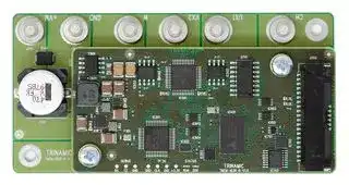
The TMCM-1636 has 9 connectors:
- 7 M4 screw terminals for supply and high voltage IO (red mark)
- 1 IO and interface connector with 40 pins (blue mark)
- 1 Brake control output connector with 2 pins (orange mark)
_Figure 1: TMCM-1636 connectors / top view_
_**NOTICE**_ **Start with power supply OFF and do not connect or disconnect motor during operation!** Motor cable and motor inductance might lead to voltage spikes when the motor is (dis)connected while energized. These voltage spikes might exceed voltage limits of the driver MOSFETs and might permanently damage them. Therefore, always switch off / disconnect power supply or at least disable driver stage before connecting / disconnecting motor. _**NOTICE**_ **Take care of polarity, wrong polarity can destroy the board!**
**Take care of polarity, wrong polarity can destroy the board!**
> ©2020 TRINAMIC Motion Control GmbH & Co. KG, Hamburg, Germany Terms of delivery and rights to technical change reserved. Download newest version at www.trinamic.com
TMCM-1636 Hardware Manual • HW Version V1.1 | Document Revision V1.20 • 2020-06-08
6 / 20
## **3.1 Screw Terminals**
Mating cables are any cables with fitting M4 cable lugs.
_**NOTICE**_ **Take care for using cables that fit to the required continuous current rating for your application!** _**NOTICE**_ **Supply cable should be as short as possible to reduce cable resistance and limit voltage drop at high load on the supply.** _**NOTICE**_ **Depending on your application make sure to add sufficient capacitors to the driver input to stabilize driver supply. Low ESR electrolyte caps are recommended, especially for higher current applications. See Section 4.1 for more information on this.**
_Figure 2: TMCM-1636 screw connectors_
|Terminal|Signal|Description|
|---|---|---|
|1|+VM|Motor supply voltage, voltage range depends on driver stage|
|2|OVP|Over-voltage protection output|
|3|GND|Signal and supply ground|
|4|W|BLDC phase W|
|5|V_X2|BLDC phase V, X2 for DC motor|
|6|U_X1|BLDC phase U, X1 for DC motor|
|7|CH/PE|Protective Earth/chassis ground|
_Table 2: TMCM-1636 screw terminals_
> ©2020 TRINAMIC Motion Control GmbH & Co. KG, Hamburg, Germany Terms of delivery and rights to technical change reserved. Download newest version at www.trinamic.com
TMCM-1636 Hardware Manual • HW Version V1.1 | Document Revision V1.20 • 2020-06-08
7 / 20
## **3.2 I/O and Interface Connector**
The connector is of type Molex Micro-Lock Plus 5054484071 (1.25mm pitch, dual row, right-angle, 40 pins). The mating connector is Molex 5054324001 (1.25mm pitch, dual row, 40 pins, positive lock, crimp housing). Use it with the following Micro-Lock Plus female crimp terminals: Molex 5054311100 (1.25mm pitch, Au plating, 26-30 AWG).
_Figure 3: TMCM-1636 I/O connector_
|Pin|Signal|Description|Pin|Signal|Description|
|---|---|---|---|---|---|
|1|COM|COM terminal of opto-<br>couplers for GPIx|2|AI0|Analog input 0,<br>0...5V<br>range|
|3|GPI0|General purpose input 0,<br>optically isolated|4|AI1|Analog input 1,<br>0...5V<br>range|
|5|GPI1|General purpose input 1,<br>optically isolated|6|GPO0|General purpose output<br>0, (open drain)|
|7|GPI2|General purpose input 2,<br>optically isolated|8|GPO1|General purpose output<br>1, (open drain)|
|9|GPI3|General purpose input 3,<br>optically isolated|10|+5V_OUT|+5V output rail for exter-<br>nal sensor supply or sig-<br>nal conditioning|
|11|HALL_UX|Digital Hall sensor input,<br>+5.0V level|12|ENC2_A|Digital quadrature/incre-<br>mental<br>encoder<br>2,<br>A<br>channel, +5.0V level|
> ©2020 TRINAMIC Motion Control GmbH & Co. KG, Hamburg, Germany Terms of delivery and rights to technical change reserved. Download newest version at www.trinamic.com
TMCM-1636 Hardware Manual • HW Version V1.1 | Document Revision V1.20 • 2020-06-08
8 / 20
|13|HALL_V|Digital Hall sensor input,<br>+5.0V level|14|ENC2_B|Digital quadrature/incre-<br>mental<br>encoder<br>2,<br>B<br>channel, +5.0V level|
|---|---|---|---|---|---|
|15|HALL_WY|Digital Hall sensor input,<br>+5.0V level|16|ENC2_N|Digital quadrature/incre-<br>mental encoder 2,<br>N<br>channel, +5.0V level|
|17|GND|Signal and supply ground|18|UART_TX|UART interface, transmit<br>line|
|19|+3.3V_OUT|+3.3V output rail|20|UART_RX|UART interface, receive<br>line|
|21|REF_L|Left reference switch in-<br>put, +5.0V level|22|ENC1_A|Digital quadrature/incre-<br>mental<br>encoder<br>1,<br>A<br>channel, +5.0V level|
|23|REF_H|Home reference switch<br>input, +5.0V level|24|ENC1_B|Digital quadrature/incre-<br>mental<br>encoder<br>1,<br>B<br>channel, +5.0V level|
|25|REF_R|Right reference switch in-<br>put, +5.0V level|26|ENC1_N|Digital quadrature/incre-<br>mental encoder 1,<br>N<br>channel, +5.0V level|
|27|GND|Signal and supply ground|28|AENC_UX|(Future use)<br>Analog<br>encoder input, 0. . . +5V|
|29|CAN_H|CAN interface, dif. signal<br>(non-inverting)|30|AENC_VN|(Future use)<br>Analog<br>encoder input, 0. . . +5V|
|31|CAN_L|CAN interface, dif. signal<br>(inverting)|32|AENC_WY|(Future use)<br>Analog<br>encoder input, 0. . . +5V|
|33|SSI_ENC_DATA_P|SSI Encoder, positive ter-<br>minal of diferential data<br>line|34|nCS_ENC|SPI / SSI Encoder, chip se-<br>lect signal, +5.0V level|
|35|SSI_ENC_DATA_N|SSI Encoder, negative ter-<br>minal of diferential data<br>line|36|SPI_ENC_SCK|SPI Encoder, clock signal,<br>+5.0V level|
|37|SSI_ENC_CLK_N|SSI Encoder, negative ter-<br>minal of diferential clock<br>line|38|SPI_ENC_MOSI|SPI Encoder, MOSI signal,<br>+5.0V level|
|39|SSI_ENC_CLK_P|SSI Encoder, positive ter-<br>minal of diferential clock<br>line|40|SPI_ENC_MISO|SPI Encoder, MISO signal,<br>+5.0V level|
_Table 3: TMCM-1636 I/O & Interface Connector_
> ©2020 TRINAMIC Motion Control GmbH & Co. KG, Hamburg, Germany Terms of delivery and rights to technical change reserved. Download newest version at www.trinamic.com
TMCM-1636 Hardware Manual • HW Version V1.1 | Document Revision V1.20 • 2020-06-08
9 / 20
## **3.3 Brake Connector**
The connector is of type Molex Micro-Lock Plus 5055680271 (1.25mm pitch, single row, vertical, 2 pins). The mating connector is Molex 5055650201 (1.25mm pitch, single row, 2 pins, positive lock, crimp housing). Use it with the following Micro-Lock Plus female crimp terminals: Molex 5054311100 (1.25mm pitch, Au plating, 26-30 AWG).
_Figure 4: TMCM-1636 screw connectors_
|Terminal|Signal|Description|
|---|---|---|
|1|+VM|Motor supply voltage, voltage range depends on driver stage|
|2|BRAKE_CTRL|PWM controlled low-side output for driving solenoids. The drive<br>current is configurable up to 1A.|
_Table 4: TMCM-1636 screw terminals_
> ©2020 TRINAMIC Motion Control GmbH & Co. KG, Hamburg, Germany Terms of delivery and rights to technical change reserved. Download newest version at www.trinamic.com
TMCM-1636 Hardware Manual • HW Version V1.1 | Document Revision V1.20 • 2020-06-08
10 / 20
## **4 Interface Circuits**
## **4.1 Supply Connection and Supply Buffering**
TMCM-1636 includes only limited onboard capacitance. For high current applications additional capacitors must be placed close to the module power input to stabilize power supply. In addition, a regulated power supply is highly recommended.
_**NOTICE**_ **Depending on your application make sure to add sufficient capacitors to the driver input to stabilize supply. Low ESR electrolyte caps are recommended. A maximum supply ripple of 0.25V (TBD) is allowed.**
**It is recommended to connect electrolytic capacitors of significant size to the power supply lines close to the TMCM-1636 ! Rule of thumb for size of electrolytic capacitor:** _C_ = 1000 _[µ] A[F][∗][I][SUP P LY]_ **The capacitors should be selected with regard to high ripple current rating. In addition to power stabilization (buffer) and filtering this added capacitor will also reduce any voltage spikes which might otherwise occur from a combination of high inductance power supply wires and the ceramic capacitors. In addition it will limit slew-rate of power supply voltage at the module. The low ESR of ceramic-only filter capacitors may cause stability problems with some switching power supplies.**
## **4.2 General Purpose Inputs**
The four general purpose inputs are optically isolated with opto-couplers. All GPI share the same COM connection.
**==> picture [64 x 59] intentionally omitted <==**
**==> picture [46 x 134] intentionally omitted <==**
**==> picture [282 x 136] intentionally omitted <==**
_Figure 5: GPIx circuit_
A separated / isolated supply may be used for the inputs – as indicated in the drawing (+24V_ISO and related GND_ISO) – but, same supply as for the TMCM-1636can be used as well.
> ©2020 TRINAMIC Motion Control GmbH & Co. KG, Hamburg, Germany Terms of delivery and rights to technical change reserved. Download newest version at www.trinamic.com
TMCM-1636 Hardware Manual • HW Version V1.1 | Document Revision V1.20 • 2020-06-08
11 / 20
## **4.3 General Purpose Outputs**
The two general purpose outputs are simple open drain outputs using n-channel FETs. The gates of the n-channel FETs are pulled low. There are no flyback diodes on the TMCM-1636.
_Figure 6: GPOx circuit_
## **4.4 Analog Inputs**
The two analog inputs go through a voltage divider and a simple filter before connecting to the microcontroller’s ADC inputs.
The analog inputs allow for a 5V input range.
The input filter has a cut-off frequency of ca. 285Hz.
## **4.5 Reference Inputs**
TMCM-1636 provides three reference inputs: Left, Right, and Home. The nput voltage range is 0V...5V.
The inputs have an internal pull-up to 5V. An input filter has a cut-off frequency of ca. 34kHz
## **4.6 Brake Control Output**
The brake control output BRAKE is a PWM controlled low-side output for driving solenoids. The drive current is configurable up to 1A.
## **4.7 Over-Voltage Protection Output**
The over-voltage protection output OVP is a low-side output for external brake resistor. It can be used to prevent the supply rail from exceeding the maximum rated values in case of overvoltage conditions.
> ©2020 TRINAMIC Motion Control GmbH & Co. KG, Hamburg, Germany Terms of delivery and rights to technical change reserved. Download newest version at www.trinamic.com
TMCM-1636 Hardware Manual • HW Version V1.1 | Document Revision V1.20 • 2020-06-08
12 / 20
## **4.8 Feedback Interfaces**
## **4.8.1 Incremental Quadrature Encoders 1 & 2**
TMCM-1636 provides two incremental quadrature encoder interfaces with A, B, and N signals each. The input voltage range is 0V...5V.
The encoder inputs have an internal pull-up to 5V. An input filter has a cut-off frequency of ca. 1.6MHz.
## **4.8.2 Analog Encoder**
TMCM-1636 provides an analog encoder interface with U, V, and W signals. The input voltage range is 0V...5V.
There are no pull resistors at this interface. An input filter has a cut-off frequency of ca. 70MHz.
## **4.8.3 Digital Hall Sensors**
TMCM-1636 provides a Hall signal interface. The input voltage range is 0V...5V. The Hall inputs have an internal pull-up to 5V. An input filter has a cut-off frequency of ca. 4kHz.
## **4.8.4 SPI-based Absolute Encoder**
TMCM-1636 provides an SPI master interface for external absolute position sensors or other peripherals (with custom firmware option). The SPI interface runs at 5V signal level.
## **4.8.5 RS422-based Absolute Encoder**
TMCM-1636 provides an RS422 interface for external absolute position sensors that use SSI or BiSS interface (depends on firmware option or custom firmware). TMCM-1636 integrates the RS422 transceiver (TI THVD1451DRBR).
The incoming RS422 data line (SSI_ENC_DATA_P and SSI_ENC_DATA_N) has an onboard termination of 120R.
> ©2020 TRINAMIC Motion Control GmbH & Co. KG, Hamburg, Germany Terms of delivery and rights to technical change reserved. Download newest version at www.trinamic.com
TMCM-1636 Hardware Manual • HW Version V1.1 | Document Revision V1.20 • 2020-06-08
13 / 20
## **5 LED Status Indicators**
The TMCM-1636 has two on-boards LED status indicators.
|LED|Description|
|---|---|
|RUN_LED|MCU/CANopen status LED, green|
|ERR_LED|MCU/CANopen error LED, red|
_Table 5: TMCM-1636 digital LED output signals_
## **6 Communication**
The following sections give some guidelines and best practices when setting up the communication bus systems supported by TMCM-1636.
## **6.1 CAN**
For remote control and communication with a host system the TMCM-1636 provides a CAN bus interface. For proper operation the following items should be taken into account when setting up a CAN network:
## 1. _BUS STRUCTURE:_
The network topology should follow a bus structure as closely as possible. That is, the connection between each node and the bus itself should be as short as possible. Basically, it should be short compared to the length of the bus.
**==> picture [416 x 128] intentionally omitted <==**
**----- Start of picture text -----**<br>
Host<br>Slave Slave Slave<br>c:><br>node node node<br>1 n - 1 n<br>}<br>termination termination<br>resistor resistor<br>(120 Ohm) (120 Ohm)<br>CAN keep distance as<br>short as possible<br>**----- End of picture text -----**<br>
_Figure 7: CAN bus structure with termination resistors_
2. _BUS TERMINATION:_
Especially for longer buses and/or multiple nodes connected to the bus and/or high communication speeds, the bus should be properly terminated at both ends. The TMCM-1636 does not integrate any termination resistor. Therefore, 120 Ohm termination resistors at both ends of the bus have to be added externally.
3. _BUS TERMINATION:_
- The bus transceiver used on the TMCM-1636 units or on the base board (TJA1042TK/3) supports at least 110 nodes under optimum conditions. Practically achievable number of nodes per CAN bus highly depend on bus length (longer bus -> less nodes) and communication speed (higher speed -> less nodes).
> ©2020 TRINAMIC Motion Control GmbH & Co. KG, Hamburg, Germany Terms of delivery and rights to technical change reserved. Download newest version at www.trinamic.com
TMCM-1636 Hardware Manual • HW Version V1.1 | Document Revision V1.20 • 2020-06-08
14 / 20
## **7 Operational Ratings and Characteristics**
## **7.1 Absolute Maximum Ratings**
|Parameter|Symbol|Min|Abs. Max|Unit|
|---|---|---|---|---|
|Motor and supply voltage +24V version|+_V M_|+12|+30|V|
|Motor and supply voltage +48V version|+_V M_|+12|+58|V|
|Abs. max. RMS motor phase current +24V version|_IphaseRMS,MAX_||601|A|
|Abs. max. RMS motor phase current +48V version|_IphaseRMS,MAX_||601|A|
|Abs. max. environmental working temperature|_TA_|-40|+852|° C|
|Max current at +5V_OUT|_IOUT_+5_V,MAX_||100|mA|
_**NOTICE**_ Stresses above those listed under "‘Absolute Maximum Ratings"’ may cause permanent damage to the device. This is a stress rating only and functional operation of the device at those or any other conditions above those indicated in the operation listings of this specification is not implied. Exposure to maximum rating conditions for extended periods may affect device reliability.
## **7.2 Operational Ratings**
Ambient temperature 25° C, if not stated otherwise.
|Parameter|Symbol|Min|Typ|Max|Unit|
|---|---|---|---|---|---|
|Motor and supply voltage +24V version|+_V M_|+12|+24|+28|V|
|Motor and supply voltage +48V version|+_V M_|+12|+48|+52|V|
|continuous RMS Motor phase current +24V version|_IphaseRMS_||30||A|
|continuous RMS Motor phase current +48V version|_IphaseRMS_||20||A|
|Working temperature|_TA_|-30||+602|° C|
## **7.3 I/O Ratings**
Ambient temperature 25° C, if not stated otherwise.
|Parameter|Symbol|Min|Typ|Max|Unit|
|---|---|---|---|---|---|
|Input voltage for analog inputs|_VAIN_|0||5.0|V|
|GPI input voltage|_VGP I_|0||24|V|
1This is the maximum current rating. This is not for continuous operation but depends on motor type, duty cycle, ambient temperature, and active/passive cooling measures.
2 Working at high environmental temperatures may require additional cooling measures depending on duty cycle and maximum current/power draw.
©2020 TRINAMIC Motion Control GmbH & Co. KG, Hamburg, Germany Terms of delivery and rights to technical change reserved. Download newest version at www.trinamic.com
TMCM-1636 Hardware Manual • HW Version V1.1 | Document Revision V1.20 • 2020-06-08
15 / 20
|GPO output voltage|_VGP O_|0||24|V|
|---|---|---|---|---|---|
|GPO sink current|_IGP O_|0||1|A|
|Brake control output voltage|_VBRAKE_|0||+VM|V|
|Brake control sink current|_IBRAKE_|0||1|A|
|Over-voltage protection output voltage|_VOV P_|0||+VM|V|
|Over-voltage protection sink current|_IOV P_|0||10|A|
|Incremental encoder input voltage|_VENC_|0||5|V|
|Analog encoder input voltage|_VAENC_|0||5|V|
|Hall signal input voltage|_VHALL_|0||5|V|
|Reference switch input voltage|_VREF_|0||5|V|
|SPI Interface voltage|_VSP I_|0||5|V|
|SSI (RS422) Interface voltage|_VSSI_|-15||+15|V|
_Table 8: I/O ratings_
## **7.4 Other Requirements**
|Specifcations|Description or Value|
|---|---|
|Cooling|Free air or heat sink mounted depending on use case, required power output,<br>and environmental temperature.|
|Working environment|Avoid dust, water, oil mist and corrosive gases, no condensation, no frosting|
_Table 9: Other Requirements and Characteristics_
> ©2020 TRINAMIC Motion Control GmbH & Co. KG, Hamburg, Germany Terms of delivery and rights to technical change reserved. Download newest version at www.trinamic.com
TMCM-1636 Hardware Manual • HW Version V1.1 | Document Revision V1.20 • 2020-06-08
16 / 20
## **8 Figures Index**
|1|TMCM-1636|connectors / top view<br>. . .|5|5 GPIx circuit<br>. . . . . . . . . . . . . . . . .|10|
|---|---|---|---|---|---|
|2|TMCM-1636|screw connectors . . . . . .|6|6 GPOx circuit . . . . . . . . . . . . . . . . .|11|
|3|TMCM-1636|I/O connector . . . . . . . .|7|7 CAN bus structure with termination||
|4|TMCM-1636|screw connectors . . . . . .|9|resistors . . . . . . . . . . . . . . . . . . .|13|
> ©2020 TRINAMIC Motion Control GmbH & Co. KG, Hamburg, Germany Terms of delivery and rights to technical change reserved. Download newest version at www.trinamic.com
TMCM-1636 Hardware Manual • HW Version V1.1 | Document Revision V1.20 • 2020-06-08
17 / 20
## **9 Tables Index**
|1|TMCM-1636|Order Codes . . . . . . . .|4|8|I/O ratings . . . . . . . . . . . . . . . . .|15|
|---|---|---|---|---|---|---|
|2|TMCM-1636|screw terminals . . . . . .|6|9|Other Requirements and Characteristics|15|
|3|TMCM-1636|I/O & Interface Connector|8|10|Hardware Revision . . . . . . . . . . . .|20|
|4|TMCM-1636|screw terminals . . . . . .|9|11|Document Revision . . . . . . . . . . . .|20|
|5|TMCM-1636|digital LED output signals|13||||
> ©2020 TRINAMIC Motion Control GmbH & Co. KG, Hamburg, Germany Terms of delivery and rights to technical change reserved. Download newest version at www.trinamic.com
TMCM-1636 Hardware Manual • HW Version V1.1 | Document Revision V1.20 • 2020-06-08
18 / 20
## **10 Supplemental Directives**
## **10.1 Producer Information**
## **10.2 Copyright**
TRINAMIC owns the content of this user manual in its entirety, including but not limited to pictures, logos, trademarks, and resources. © Copyright 2020 TRINAMIC. All rights reserved. Electronically published by TRINAMIC, Germany.
Redistributions of source or derived format (for example, Portable Document Format or Hypertext Markup Language) must retain the above copyright notice, and the complete Datasheet User Manual documentation of this product including associated Application Notes; and a reference to other available product-related documentation.
## **10.3 Trademark Designations and Symbols**
Trademark designations and symbols used in this documentation indicate that a product or feature is owned and registered as trademark and/or patent either by TRINAMIC or by other manufacturers, whose products are used or referred to in combination with TRINAMIC’s products and TRINAMIC’s product documentation.
This Hardware Manual is a non-commercial publication that seeks to provide concise scientific and technical user information to the target user. Thus, trademark designations and symbols are only entered in the Short Spec of this document that introduces the product at a quick glance. The trademark designation /symbol is also entered when the product or feature name occurs for the first time in the document. All trademarks and brand names used are property of their respective owners.
## **10.4 Target User**
The documentation provided here, is for programmers and engineers only, who are equipped with the necessary skills and have been trained to work with this type of product.
The Target User knows how to responsibly make use of this product without causing harm to himself or others, and without causing damage to systems or devices, in which the user incorporates the product.
## **10.5 Disclaimer: Life Support Systems**
TRINAMIC Motion Control GmbH & Co. KG does not authorize or warrant any of its products for use in life support systems, without the specific written consent of TRINAMIC Motion Control GmbH & Co. KG.
Life support systems are equipment intended to support or sustain life, and whose failure to perform, when properly used in accordance with instructions provided, can be reasonably expected to result in personal injury or death.
Information given in this document is believed to be accurate and reliable. However, no responsibility is assumed for the consequences of its use nor for any infringement of patents or other rights of third parties which may result from its use. Specifications are subject to change without notice.
## **10.6 Disclaimer: Intended Use**
The data specified in this user manual is intended solely for the purpose of product description. No representations or warranties, either express or implied, of merchantability, fitness for a particular purpose
> ©2020 TRINAMIC Motion Control GmbH & Co. KG, Hamburg, Germany Terms of delivery and rights to technical change reserved. Download newest version at www.trinamic.com
TMCM-1636 Hardware Manual • HW Version V1.1 | Document Revision V1.20 • 2020-06-08
19 / 20
or of any other nature are made hereunder with respect to information/specification or the products to which information refers and no guarantee with respect to compliance to the intended use is given.
In particular, this also applies to the stated possible applications or areas of applications of the product. TRINAMIC products are not designed for and must not be used in connection with any applications where the failure of such products would reasonably be expected to result in significant personal injury or death (safety-Critical Applications) without TRINAMIC’s specific written consent.
TRINAMIC products are not designed nor intended for use in military or aerospace applications or environments or in automotive applications unless specifically designated for such use by TRINAMIC. TRINAMIC conveys no patent, copyright, mask work right or other trade mark right to this product. TRINAMIC assumes no liability for any patent and/or other trade mark rights of a third party resulting from processing or handling of the product and/or any other use of the product.
## **10.7 Collateral Documents & Tools**
This product documentation is related and/or associated with additional tool kits, firmware and other items, as provided on the product page at: www.trinamic.com.
> ©2020 TRINAMIC Motion Control GmbH & Co. KG, Hamburg, Germany Terms of delivery and rights to technical change reserved. Download newest version at www.trinamic.com
TMCM-1636 Hardware Manual • HW Version V1.1 | Document Revision V1.20 • 2020-06-08
20 / 20
## **11 Revision History**
## **11.1 Hardware Revision**
|Version|Date|Author|Description|
|---|---|---|---|
|V1.1|2020-01-06||Release Version|
_Table 10: Hardware Revision_
## **11.2 Document Revision**
|Version|Date|Author|Description|
|---|---|---|---|
|V1.20|2020-06-08|SK/MM|Realease version|
_Table 11: Document Revision_
> ©2020 TRINAMIC Motion Control GmbH & Co. KG, Hamburg, Germany Terms of delivery and rights to technical change reserved. Download newest version at www.trinamic.com
Updated at April 29, 2026
About Novapart
Novapart is a B2B electronic component broker specialising in stock shortages and cost reduction. We source hard-to-find parts and identify compliant alternatives across a catalogue of 410,000+ components from 500+ manufacturers.
Learn more →Stock Shortage Specialist
When a component is unavailable, discontinued or has an unacceptable lead time, we tap into our network of vetted European and Asian distributors to source what you need — without compromising on quality or traceability.
Request a quote →Compliant Alternatives
We identify pin-to-pin, electrically equivalent substitutes that meet the same certifications (RoHS, AEC-Q100, REACH) as your original specification — validated against datasheets, not just part numbers. Often at a lower cost.
BOM Analysis service →