
Image not available
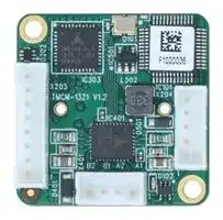
Illustrative purposes only

TMCM-1321
CONTROLLER/DRIVER MOD, 2-PH, 0.7A, 9-28V
⚠️ Reference pricing provided. In case of supply shortages, we will connect you with our trusted procurement partners to ensure your project's continuity.
- Manufacturer: TRINAMIC / ANALOG DEVICES
- Product type: Stepper Motor Drives
- SVHC: No SVHC (04-Feb-2026)
- No. of Phases: Two Phase
- Product Range: -
- Output Current Max: 700mA
- Supply Voltage Max: 28V
- Supply Voltage Min: 9V
- Control / Drive Type: Controller / Driver Module
| Delivery and price | |
|---|---|
| Units per pack | 1 |
| Price | 152.63 € |
| Current stock | 10+ |
| Lead time | 30 days |
Datasheet

**MODULE**

**Module for Stepper**

## TMCM-1321 Hardware Manual

## Hardware Version V1.2 | Document Revision V1.01 • 2021-MAR-04

**The TMCM-1321 is an easy to use, single axis controller/driver for 2-phase bipolar stepper motors with separate home and stop switch inputs. The built-in magnetic encoder can be used when a suitable magnet is attached to the motor axis, enabling also closed-loop operation. As an alternative, an optical encoder can be connected via digital ABN inputs. Different ramp shapes can be selected. Dynamic current control, and quiet, smooth and efficient operation are combined with StallGuard™and CoolStep™features.**

Features

- Single axis stepper motor control

- Supply voltage 24V DC

- Up to 0.7A RMS (1A peak) motor current

- Hardware motion contoller with different types of ramps

- Closed-loop operation possible

- RS485 interface

- General purpose inputs and outputs

- ABN encoder input

- Built-in magnetic encoder chip

## Applications

- Laboratory Automation

- Manufacturing

- Semiconductor Handling

   - Life Science

- Robotics

- Factory Automation • Biotechnology

- Test & Measurement • Liquid Handling

## Simplified Block Diagram

> ©2021 TRINAMIC Motion Control GmbH & Co. KG, Hamburg, Germany Terms of delivery and rights to technical change reserved. Download newest version at: www.trinamic.com

Read entire documentation.

TMCM-1321 Hardware Manual • Hardware Version V1.2 | Document Revision V1.01 • 2021-MAR-04

2 / 17

## **Contents**

|**1**|**Features**|**Features**||**3**|
|---|---|---|---|---|
||1.1|General Features . .|. . . . . . . . . . . . . . . . . . . . . . . . . . . . . . . . . . . . . . . . . . .|3|
|**2**|**Order Codes**|||**4**|
|**3**|**Mechanical and Electrical Interfacing**|||**5**|
||3.1|TMCM-1321 Dimensions . . . . . . . . . . . . . . . . . . . . . . . . . . . . . . . . . . . . . . . . .||5|
||3.2|Mounting Considerations . . . . . . . . . . . . . . . . . . . . . . . . . . . . . . . . . . . . . . . .||5|
|**4**|**Connectors and LEDs**|||**6**|
||4.1|Power supply and I/O|Connector . . . . . . . . . . . . . . . . . . . . . . . . . . . . . . . . . . . .|6|
||4.2|Motor Connector . .|. . . . . . . . . . . . . . . . . . . . . . . . . . . . . . . . . . . . . . . . . . .|7|
||4.3|Encoder Connector .|. . . . . . . . . . . . . . . . . . . . . . . . . . . . . . . . . . . . . . . . . . .|7|
||4.4|RS485 Connection<br>.|. . . . . . . . . . . . . . . . . . . . . . . . . . . . . . . . . . . . . . . . . . .|8|
||4.5|RS485 Bus Adapters|. . . . . . . . . . . . . . . . . . . . . . . . . . . . . . . . . . . . . . . . . . .|9|
||4.6|Status LED . . . . . .|. . . . . . . . . . . . . . . . . . . . . . . . . . . . . . . . . . . . . . . . . . .|9|
|**5**|**Operational Ratings and Characteristics**|||**11**|
||5.1|Absolute Maximum Ratings . . . . . . . . . . . . . . . . . . . . . . . . . . . . . . . . . . . . . . .||11|
||5.2|Electrical Characteristics (Ambient Temperature 25° C) . . . . . . . . . . . . . . . . . . . . . . .||11|
||5.3|I/O Ratings (Ambient Temperature 25° C) . . . . . . . . . . . . . . . . . . . . . . . . . . . . . . .||11|
||5.4|Functional Characteristics . . . . . . . . . . . . . . . . . . . . . . . . . . . . . . . . . . . . . . . .||12|
||5.5|Other Requirements|. . . . . . . . . . . . . . . . . . . . . . . . . . . . . . . . . . . . . . . . . . .|12|
|**6**|**Figures Index**|||**13**|
|**7**|**Tables Index**|||**14**|
|**8**|**Supplemental Directives**|||**15**|
||8.1|Producer Information|. . . . . . . . . . . . . . . . . . . . . . . . . . . . . . . . . . . . . . . . . .|15|
||8.2|Copyright . . . . . . .|. . . . . . . . . . . . . . . . . . . . . . . . . . . . . . . . . . . . . . . . . . .|15|
||8.3|Trademark Designations and Symbols. . . . . . . . . . . . . . . . . . . . . . . . . . . . . . . . .||15|
||8.4|Target User<br>. . . . .|. . . . . . . . . . . . . . . . . . . . . . . . . . . . . . . . . . . . . . . . . . .|15|
||8.5|Disclaimer: Life Support Systems . . . . . . . . . . . . . . . . . . . . . . . . . . . . . . . . . . . .||15|
||8.6|Disclaimer: Intended Use<br>. . . . . . . . . . . . . . . . . . . . . . . . . . . . . . . . . . . . . . . .||15|
||8.7|Collateral Documents|& Tools. . . . . . . . . . . . . . . . . . . . . . . . . . . . . . . . . . . . . .|16|
|**9**|**Revision History**|||**17**|
||9.1|Hardware Revision .|. . . . . . . . . . . . . . . . . . . . . . . . . . . . . . . . . . . . . . . . . . .|17|
||9.2|Document Revision .|. . . . . . . . . . . . . . . . . . . . . . . . . . . . . . . . . . . . . . . . . . .|17|


> ©2021 TRINAMIC Motion Control GmbH & Co. KG, Hamburg, Germany Terms of delivery and rights to technical change reserved. Download newest version at www.trinamic.com

TMCM-1321 Hardware Manual • Hardware Version V1.2 | Document Revision V1.01 • 2021-MAR-04

3 / 17

## **1 Features**

The TMCM-1321 is a highly integrated stepper motor driver and controller and includes a fully featured hardware motion controller and magnetic encoder chip. It drives up to 0.7A RMS motor phase current at 24V nominal. Configuration and control is possible via its RS485 bus interface. The module can directly be mounted on the back bell of standard NEMA11 stepper motors which are equipped with a diametrical 2-pole magnet in their rear shaft. As an alternative, an optical encoder (mounted directly on the motor shaft) can be used instead of the magnet.

## **1.1 General Features**

## **Main Characteristics**

- Supply Voltage +24V nom. (+9V to +28V DC)

- Motor driver stage with 0.7A RMS phase current

- Highest micro step resolution, up to 256 micro steps per full step

- Magnet encoder chip (AS5047) with 14 bit resolution (16384cpr) for position feedback

- ABN encoder interface

- EEPROM for permanent onboard parameter storage

- Advanced s-shape ramps hardware motion controller (TMC4361A-LA)

- Home and stop switch inputs, also usable as general purpose inputs

- One general purpose output

- High performance SpreadCycle™chopper mode

- High-precision sensorless load measurement using StallGuard2™

- Automatic current scaling algorithm CoolStep™to save energy and keep your drive cool

## **RS485 Bus Interface**

- Standard RS485 Bus Interface for control and configuration

- Bit rates of up to 115200bps

- TMCL protocol

- Firmware update via RS485

> ©2021 TRINAMIC Motion Control GmbH & Co. KG, Hamburg, Germany Terms of delivery and rights to technical change reserved. Download newest version at www.trinamic.com

TMCM-1321 Hardware Manual • Hardware Version V1.2 | Document Revision V1.01 • 2021-MAR-04

4 / 17

## **2 Order Codes**

|Order Code|Description|Size (LxW)|
|---|---|---|
|TMCM-1321|Module, 0.7A RMS, +24V DC, RS485 Bus interface, TMCL frmware|28mm x 28mm|


_Table 1: Order codes_

|Order Code|Description|
|---|---|
|TMCM-1321-CABLE|Cable loom for TMCM-1321:<br>• 1x cable loom for motor connector with 4-pin JST PH series connector<br>• 1x cable loom for encoder connector with 5-pin JST PH series connector<br>• 1x cable loom for power, interface and I/O connector with 8-pin JST PH se-<br>ries connector|


_Table 2: Order codes cable loom_

©2021 TRINAMIC Motion Control GmbH & Co. KG, Hamburg, Germany Terms of delivery and rights to technical change reserved. Download newest version at www.trinamic.com

TMCM-1321 Hardware Manual • Hardware Version V1.2 | Document Revision V1.01 • 2021-MAR-04

5 / 17

## **3 Mechanical and Electrical Interfacing**

## **3.1 TMCM-1321 Dimensions**

TMCM-1321 has a size of 28mm x 28mm with round-shaped corners. It has two M2.5 mounting holes that allow for easy assembly to the back bell of a standard NEMA11 stepper motor. Motor, Power and I/O connectors are placed on opposite edges of the board.

2.5mm

**==> picture [194 x 176] intentionally omitted <==**

**----- Start of picture text -----**<br>
28mm PCB<br>25.5mm<br>2.5mm<br>25.5mm<br>28mm<br>In<br>**----- End of picture text -----**<br>


_Figure 1: TMCM-1321 dimensions_

## **3.2 Mounting Considerations**

The module can directly be mounted on the back bell of standard NEMA11 stepper motors. If the built-in magnetic encoder is to be used a diametrical two pole magnet has to be mounted onto the rear shaft of the motor. If an optical encoder is to be used the optical encoder has to be mounted to the motor shaft (without any gearing in between). The TMCM-1321 module has two metal plated mounting holes. Both mounting holes are connected to board supply ground. Please keep this in mind when mounting the board to the rear side of a motor.

**==> picture [231 x 118] intentionally omitted <==**

**----- Start of picture text -----**<br>
TMCM-1321<br>it:<br>Motor Magnet<br>**----- End of picture text -----**<br>


_Figure 2: TMCM-1321 example motor assembly_

©2021 TRINAMIC Motion Control GmbH & Co. KG, Hamburg, Germany Terms of delivery and rights to technical change reserved. Download newest version at www.trinamic.com

TMCM-1321 Hardware Manual • Hardware Version V1.2 | Document Revision V1.01 • 2021-MAR-04

6 / 17

## **4 Connectors and LEDs**

The TMCM-1321 is equipped with three connectors – one 8-pin connector for power supply, communication (RS485) and I/O, one 5-pin connector for external ABN encoders and one 4-pin connector for connecting the stepper motor.

_Figure 3: TMCM-1321 connectors_

Overview of connector and mating connector types:

|Label|Connector type|Mating connector type|
|---|---|---|
|Power supply and I/O connector|JST PH series, 8 pins, 0.1" pitch|Connector housing: JST PHR-8<br>Contacts, Wire: AWG 24|
|Encoder connector|JST PH series, 5 pins, 0.1" pitch|Connector housing: JST PHR-5<br>Contacts, Wire: AWG 24|
|Motor connector|JST PH series, 4 pins, 0.1" pitch|Connector housing:<br>JST PHR-4<br>Contacts, Wire: AWG 24|


_Table 3: Connector and mating connectors_

## **4.1 Power supply and I/O Connector**

|Pin no.|Pin name|Description|
|---|---|---|
|1|GND|Supply and signal ground connection|
|2|+24V|Supply voltage input (+6V to +28V DC)|
|3|RS485+|RS485 bus interface (non-inverting)|
|4|RS485-|RS485 bus interface (inverting)|
|5|OUT0|General purpose output, open drain|
|6|HOME / IN0|Home switch input, also usable as general purpose input (+24V compatible)|
|7|STOPL / IN1|Left stop switch input, also usable as general purpose input (+24V compatible)|
|8|STOPR / IN2|Right stop switch input, also usable as general purpose input (+24V compati-<br>ble)|


_Table 4: TMCM-1321 Power supply and I/O connector pin assignment_

> ©2021 TRINAMIC Motion Control GmbH & Co. KG, Hamburg, Germany Terms of delivery and rights to technical change reserved. Download newest version at www.trinamic.com

TMCM-1321 Hardware Manual • Hardware Version V1.2 | Document Revision V1.01 • 2021-MAR-04

7 / 17

|**_NOTICE_**|**Always keep the power supply voltage below the upper limit of 28V!** Oth-<br>|
|---|---|
|erwise the driver electronics will be seriously damaged. Especially, when the se-<br>lected operating voltage is near the upper limit a regulated power supply is highly<br>recommended.||
|||
|**_NOTICE_**|**Add external power supply capacitors!** It is recommended to connect an elec-<br>|
|trolytic capacitor of signifcant size (e.g. 470_µ_F/35V) to the power supply lines<br>next to the TMCM-1321!<br>Rule of thumb for size of electrolytic capacitor: _C_ = 1000_µF_<br>_A_<br>_× ISUP P LY_<br>In addition to power stabilization (bufer) and fltering this added capacitor will<br>also reduce any voltage spikes which might otherwise occur from a combination<br>of high inductance power supply wires and the ceramic capacitors. In addition it<br>will limit slew-rate of power supply voltage at the module. The low ESR of ceramic-<br>only flter capacitors may cause stability problems with some switching power<br>supplies.||


## **4.2 Motor Connector**

|Pin no.|Pin name|Description|
|---|---|---|
|1|A1|Motor phase A pin 1|
|2|A2|Motor phase A pin 2|
|3|B1|Motor phase B pin 1|
|4|B2|Motor phase B pin 2|


_Table 5: Motor connector pinning_

_**NOTICE**_ **Do not connect or disconnect motor during operation!** Motor cable and motor inductivity might lead to voltage spikes when the motor is connected / disconnected while energized. These voltage spikes might exceed voltage limits of the driver MOSFETs and might permanently damage them. Therefore, always switch off or disconnect power supply before connecting or disconnecting the motor.

## **4.3 Encoder Connector**

|Pin no.|Pin name|Description|
|---|---|---|
|1|GND|Supply and signal ground|
|2|+5V|+5V encoder supply output|
|3|A|Encoder A channel|
|4|B|Encoder B channel|
|5|N|Encoder null channel|


_Table 6: Motor connector pinning_

> ©2021 TRINAMIC Motion Control GmbH & Co. KG, Hamburg, Germany Terms of delivery and rights to technical change reserved. Download newest version at www.trinamic.com

TMCM-1321 Hardware Manual • Hardware Version V1.2 | Document Revision V1.01 • 2021-MAR-04

8 / 17

## **4.4 RS485 Connection**

For remote control and communication with a host system the TMCM-1321 provides a RS485 bus interface. For proper operation the following items should be taken into account:

## 1. _BUS STRUCTURE:_

The network topology should follow a bus structure as closely as possible. That is, the connection between each node and the bus itself should be as short as possible. Basically, it should be short compared to the length of the bus.

**==> picture [416 x 129] intentionally omitted <==**

**----- Start of picture text -----**<br>
Host<br>Slave Slave Slave<br>c:><br>node node node<br>1 n - 1 n<br>}<br>termination termination<br>resistor resistor<br>(120 Ohm) (120 Ohm)<br>RS485 keep distance as<br>short as possible<br>**----- End of picture text -----**<br>


_Figure 4: RS485 bus structure with termination resistors_

2. _BUS TERMINATION:_

   - Especially for longer buses and/or multiple nodes connected to the bus and/or high communication speeds, the bus should be properly terminated at both ends. The TMCM-1321 does not integrate any termination resistor. Therefore, 120 Ohm termination resistors at both ends of the bus have to be added externally.

3. _NUMBER OF NODES:_

   - The RS485 electrical interface standard (EIA-485) allows up to 32 nodes to be connected to a single bus. The bus transceiver used on the TMCM-1321 units (SN65HVD1781D) offers a significantly reduced bus load compared to the standard and allows a maximum of 255 units to be connected to a single RS485 bus using standard TMCL firmware. _Please note: usually it cannot be expected to get reliable communication with the maximum number of nodes connected to one bus and maximum supported communication speed at the same time. Instead, a compromise has to be found between bus cable length, communication speed and number of nodes._

4. _COMMUNICATION SPEED:_

   - The maximum RS485 communication speed supported by the TMCM-1321 hardware is 1Mbit/s. Factory default is 9600 bit/s. Please see separate TMCM-1321 TMCL firmware manual for information regarding other possible communication speeds below the upper hardware limit.

5. _NO FLOATING BUS LINES:_

   - Avoid floating bus lines while neither the host/master nor one of the slaves along the bus line is transmitting data (all bus nodes switched to receive mode). Floating bus lines may lead to communication errors. In order to ensure valid signals on the bus it is recommended to use a resistor network connecting both bus lines to well defined logic levels.

There are actually two options which can be recommended: Add resistor (bias) network on one side of the bus, only (120R termination resistor still at both ends):

> ©2021 TRINAMIC Motion Control GmbH & Co. KG, Hamburg, Germany Terms of delivery and rights to technical change reserved. Download newest version at www.trinamic.com

TMCM-1321 Hardware Manual • Hardware Version V1.2 | Document Revision V1.01 • 2021-MAR-04

9 / 17

**==> picture [380 x 138] intentionally omitted <==**

**----- Start of picture text -----**<br>
Slave Slave<br>node node +5V<br>n  - 1 n<br>pull-up (680R)<br>termination RS485+ / RS485A termination<br>resistor resistor<br>(120R) RS485- / RS485B (120R)<br>pull-down (680R)<br>GND<br>**----- End of picture text -----**<br>


_Figure 5: RS485 bus lines with resistor (bias) network on one side, only_

Or add resistor network at both ends of the bus (like Profibus™termination):

**==> picture [406 x 138] intentionally omitted <==**

**----- Start of picture text -----**<br>
Slave Slave<br>+5V node node +5V<br>n  - 1 n<br>pull-up (390R) pull-up (390R)<br>termination RS485+ / RS485A termination<br>resistor resistor<br>(220R) RS485- / RS485B (220R)<br>pull-down (390R) pull-down (390R)<br>GND GND<br>**----- End of picture text -----**<br>


_Figure 6: RS485 bus lines with Profibus™recommended line termination_

## **4.5 RS485 Bus Adapters**

To quickly connect to the TMCM-1321 a PC based integrated development environment called TMCL-IDE is available. The latest release can be downloaded for free from our web site: www.trinamic.com A number of common CAN interface adapters from different manufactures is supported from within this software. Please make sure to check our web site from time to time for the latest version of the software!

## **4.6 Status LED**

The TMCM-1321 module is equipped with a green status LED. When in TMCL mode the LED is blinking. When in boot loader mode the LED is constantly on.

> ©2021 TRINAMIC Motion Control GmbH & Co. KG, Hamburg, Germany Terms of delivery and rights to technical change reserved. Download newest version at www.trinamic.com

TMCM-1321 Hardware Manual • Hardware Version V1.2 | Document Revision V1.01 • 2021-MAR-04

10 / 17

_Figure 7: TMCM-1321 LED_

©2021 TRINAMIC Motion Control GmbH & Co. KG, Hamburg, Germany Terms of delivery and rights to technical change reserved. Download newest version at www.trinamic.com

TMCM-1321 Hardware Manual • Hardware Version V1.2 | Document Revision V1.01 • 2021-MAR-04

11 / 17

## **5 Operational Ratings and Characteristics**

## **5.1 Absolute Maximum Ratings**

|Parameter|Min|Max|Unit|
|---|---|---|---|
|Supply voltage|+9|+28|V|
|Working temperature|-30|+40|° C|
|Motor coil current / sine wave**peak**||1.0|A|
|Continuous motor current (**RMS**)||0.7|A|


_**NOTICE**_ Stresses above those listed under "‘Absolute Maximum Ratings"’ may cause permanent damage to the device. This is a stress rating only and functional operation of the device at those or any other conditions above those indicated in the operation listings of this specification is not implied. Exposure to maximum rating conditions for extended periods may affect device reliability.

## **5.2 Electrical Characteristics (Ambient Temperature 25° C)**

|Parameter|Symbol|Min|Typ|Max|Unit|
|---|---|---|---|---|---|
|Supply voltage|_V DD_|9|24|28|V|
|Motor coil current / sine wave **peak** (chopper regulated, ad-<br>justable via RS485 interface)|_ICOILpeak_|0||1.0|A|
|Continuous motor current (**RMS**)|_ICOILRMS_|0||0.7|A|


_Table 8: Electrical Characteristics_

## **5.3 I/O Ratings (Ambient Temperature 25° C)**

|Parameter|Symbol|Min|Typ|Max|Unit|
|---|---|---|---|---|---|
|Input voltage|_VIN_||5|5.5|V|
|Low level voltage|_VL_|0||1.75|V|
|High level voltage|_VH_|3.25||5|V|


_Table 9: I/O ratings_

> ©2021 TRINAMIC Motion Control GmbH & Co. KG, Hamburg, Germany Terms of delivery and rights to technical change reserved. Download newest version at www.trinamic.com

TMCM-1321 Hardware Manual • Hardware Version V1.2 | Document Revision V1.01 • 2021-MAR-04

12 / 17

## **5.4 Functional Characteristics**

|Parameter|Description / Value|
|---|---|
|Control|RS485 bus interface, four digital inputs, one confgurable output|
|Communication|RS485 bus interface for control and confguration using TMCL protocol, up to<br>115200bps (default 9600bps)|
|Driving Mode|spreadCycle, constant _Toff_ chopper, adaptive current control via stallGuard2<br>and coolstep|
|Stepping Resolution|Full, 1/2, 1/4, 1/8, 1/16, 1/32, 1/64, 1/128, 1/256 step|


_Table 10: Functional Characteristics_

## **5.5 Other Requirements**

|Specifcations|Description or Value|
|---|---|
|Cooling|Free air|
|Working environment|Avoid dust, water, oil mist and corrosive gases, no condensation, no frosting|
|Working temperature|-30° C to +40° C|


_Table 11: Other Requirements and Characteristics_

> ©2021 TRINAMIC Motion Control GmbH & Co. KG, Hamburg, Germany Terms of delivery and rights to technical change reserved. Download newest version at www.trinamic.com

TMCM-1321 Hardware Manual • Hardware Version V1.2 | Document Revision V1.01 • 2021-MAR-04

13 / 17

## **6 Figures Index**

- 1 TMCM-1321 dimensions . . . . . . . . 5 5 RS485 bus lines with resistor (bias) 2 TMCM-1321 example motor assembly 5 network on one side, only . . . . . . . 9 3 TMCM-1321 connectors . . . . . . . . 6 6 RS485 bus lines with Profibus™recommended 4 RS485 bus structure with termination line termination . . . . . . . . . . . . . 9 resistors . . . . . . . . . . . . . . . . . 8 7 TMCM-1321 LED . . . . . . . . . . . . . 10

> ©2021 TRINAMIC Motion Control GmbH & Co. KG, Hamburg, Germany Terms of delivery and rights to technical change reserved. Download newest version at www.trinamic.com

TMCM-1321 Hardware Manual • Hardware Version V1.2 | Document Revision V1.01 • 2021-MAR-04

14 / 17

## **7 Tables Index**

|1|Order codes . . . . . . . . . . . . . . .|4|8|Electrical Characteristics . . . . . . . .|11|
|---|---|---|---|---|---|
|2|Order codes cable loom . . . . . . . .|4|9|I/O ratings . . . . . . . . . . . . . . . .|11|
|3|Connector and mating connectors . .|6|10|Functional Characteristics . . . . . . .|12|
|4|TMCM-1321 Power supply and I/O||11|Other Requirements and Characteris-||
||connector pin assignment . . . . . . .|6||tics. . . . . . . . . . . . . . . . . . . . .|12|
|5|Motor connector pinning<br>. . . . . . .|7|12|Hardware Revision . . . . . . . . . . .|17|
|6|Motor connector pinning<br>. . . . . . .|7|13|Document Revision . . . . . . . . . . .|17|


©2021 TRINAMIC Motion Control GmbH & Co. KG, Hamburg, Germany Terms of delivery and rights to technical change reserved. Download newest version at www.trinamic.com

TMCM-1321 Hardware Manual • Hardware Version V1.2 | Document Revision V1.01 • 2021-MAR-04

15 / 17

## **8 Supplemental Directives**

## **8.1 Producer Information**

## **8.2 Copyright**

TRINAMIC owns the content of this user manual in its entirety, including but not limited to pictures, logos, trademarks, and resources. © Copyright 2021 TRINAMIC. All rights reserved. Electronically published by TRINAMIC, Germany.

Redistributions of source or derived format (for example, Portable Document Format or Hypertext Markup Language) must retain the above copyright notice, and the complete Datasheet User Manual documentation of this product including associated Application Notes; and a reference to other available productrelated documentation.

## **8.3 Trademark Designations and Symbols**

Trademark designations and symbols used in this documentation indicate that a product or feature is owned and registered as trademark and/or patent either by TRINAMIC or by other manufacturers, whose products are used or referred to in combination with TRINAMIC’s products and TRINAMIC’s product documentation.

This Hardware Manual is a non-commercial publication that seeks to provide concise scientific and technical user information to the target user. Thus, trademark designations and symbols are only entered in the Short Spec of this document that introduces the product at a quick glance. The trademark designation /symbol is also entered when the product or feature name occurs for the first time in the document. All trademarks and brand names used are property of their respective owners.

## **8.4 Target User**

The documentation provided here, is for programmers and engineers only, who are equipped with the necessary skills and have been trained to work with this type of product.

The Target User knows how to responsibly make use of this product without causing harm to himself or others, and without causing damage to systems or devices, in which the user incorporates the product.

## **8.5 Disclaimer: Life Support Systems**

TRINAMIC Motion Control GmbH & Co. KG does not authorize or warrant any of its products for use in life support systems, without the specific written consent of TRINAMIC Motion Control GmbH & Co. KG.

Life support systems are equipment intended to support or sustain life, and whose failure to perform, when properly used in accordance with instructions provided, can be reasonably expected to result in personal injury or death.

Information given in this document is believed to be accurate and reliable. However, no responsibility is assumed for the consequences of its use nor for any infringement of patents or other rights of third parties which may result from its use. Specifications are subject to change without notice.

## **8.6 Disclaimer: Intended Use**

The data specified in this user manual is intended solely for the purpose of product description. No representations or warranties, either express or implied, of merchantability, fitness for a particular purpose

> ©2021 TRINAMIC Motion Control GmbH & Co. KG, Hamburg, Germany Terms of delivery and rights to technical change reserved. Download newest version at www.trinamic.com

TMCM-1321 Hardware Manual • Hardware Version V1.2 | Document Revision V1.01 • 2021-MAR-04

16 / 17

or of any other nature are made hereunder with respect to information/specification or the products to which information refers and no guarantee with respect to compliance to the intended use is given.

In particular, this also applies to the stated possible applications or areas of applications of the product. TRINAMIC products are not designed for and must not be used in connection with any applications where the failure of such products would reasonably be expected to result in significant personal injury or death (safety-Critical Applications) without TRINAMIC’s specific written consent.

TRINAMIC products are not designed nor intended for use in military or aerospace applications or environments or in automotive applications unless specifically designated for such use by TRINAMIC. TRINAMIC conveys no patent, copyright, mask work right or other trade mark right to this product. TRINAMIC assumes no liability for any patent and/or other trade mark rights of a third party resulting from processing or handling of the product and/or any other use of the product.

## **8.7 Collateral Documents & Tools**

This product documentation is related and/or associated with additional tool kits, firmware and other items, as provided on the product page at: www.trinamic.com.

> ©2021 TRINAMIC Motion Control GmbH & Co. KG, Hamburg, Germany Terms of delivery and rights to technical change reserved. Download newest version at www.trinamic.com

TMCM-1321 Hardware Manual • Hardware Version V1.2 | Document Revision V1.01 • 2021-MAR-04

17 / 17

## **9 Revision History**

## **9.1 Hardware Revision**

|Version|Date|Author|Description|
|---|---|---|---|
|1.2|2021-01-22|TMC|First release.|


_Table 12: Hardware Revision_

## **9.2 Document Revision**

|Version|Date|Author|Description|
|---|---|---|---|
|1.00|2021-01-22|TMC|First release.|
|1.01|2021-03-04|TMC|Updated application list.|


_Table 13: Document Revision_

©2021 TRINAMIC Motion Control GmbH & Co. KG, Hamburg, Germany Terms of delivery and rights to technical change reserved. Download newest version at www.trinamic.com
Updated at April 29, 2026
About Novapart
Novapart is a B2B electronic component broker specialising in stock shortages and cost reduction. We source hard-to-find parts and identify compliant alternatives across a catalogue of 410,000+ components from 500+ manufacturers.
Learn more →Stock Shortage Specialist
When a component is unavailable, discontinued or has an unacceptable lead time, we tap into our network of vetted European and Asian distributors to source what you need — without compromising on quality or traceability.
Request a quote →Compliant Alternatives
We identify pin-to-pin, electrically equivalent substitutes that meet the same certifications (RoHS, AEC-Q100, REACH) as your original specification — validated against datasheets, not just part numbers. Often at a lower cost.
BOM Analysis service →