
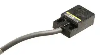


TL-W5MC1
INDUCTIVE PROXIMITY SENSOR
- Manufacturer: OMRON INDUSTRIAL AUTOMATION
- Product type: Inductive Proximity Sensors
- Sensor Type:Inductive Proximity Sensor; Operating Temperature Max:70°C; Supply Voltage Min:10VDC; Supply Voltage Max:30VDC; Sensor Output Type:3-Wire, NPN, NO; Sensor Case 27M2898
- Sensor Type: Inductive Proximity Sensor
- Product Range: -
- Supply Voltage Max: 30VDC
- Supply Voltage Min: 10VDC
- Sensing Distance Nom: 5mm
- Sensor Case / Package: Module
| Delivery and price | |
|---|---|
| Units per pack | 1 |
| Price | 100.26 € |
| Current stock | 10+ |
| Lead time | 30 days |
**Flat Inductive Proximity Sensor TL-W**

CSM_TL-W_DS_E_10_1

## **Standard Flat Sensors in Many Different Variations**

- Only 6 mm thick yet provides a sensing distance of 3 mm (TL-W3MC1).

- Aluminum die-cast models also available.

Be sure to read _Safety Precautions_ on page 7.

For the most recent information on models that have been certified for safety standards, refer to your OMRON website.

## **Ordering Information**

**Sensors [Refer to** _**Dimensions**_ **on page 8.]**

**DC 2-Wire Models**

|**Appearance**|**Sensing distance**|**Sensing distance**|**Sensing distance**|**Sensing distance**|**Output configuration**|**Model**|**Model**|
|---|---|---|---|---|---|---|---|
|||||||**Operation mode**||
|||||||**NO**|**NC**|
|Unshielded<br>c~~+~~|1.5 mm|1.5 mm|||DC 3-wire, NPN|**TL-W1R5MC1 2M**<br>***1**<br>***2**<br>***3**|---|
||3 mm|3 mm||||**TL-W3MC1 2M**<br>***1**<br>***2**<br>***3**|**TL-W3MC2 2M**<br>***1**<br>***2**<br>***3**|
||5 mm|5 mm||||**TL-W5MC1 2M**<br>***1**<br>***2**<br>***3**|**TL-W5MC2 2M**<br>***2**|
||||20 mm|20 mm||**TL-W20ME1 2M**<br>***1**<br>***2**<br>***3**|**TL-W20ME2 2M**<br>***1**|
|||||||||
|||||||||
|Shielded<br>to~~h~~|5 mm|5 mm|||DC 3-wire, NPN|**TL-W5E1 2M**|**TL-W5E2 2M**|
||||||DC 3-wire, PNP|**TL-W5F1 2M**|**TL-W5F2 2M**|


*1. Models with a different frequency are also available to prevent mutual interference. The model numbers are TL-W @ M @@ 5 (e.g., TL-W5MD15).

- *2. Models with PNP outputs are also available. Ask your OMRON representative for details.

- *3. Models are also available with robotics (bend resistant) cables. Add “-R” to the model number. (e.g., TL-W5MC1-R 2M)

**1** omron ~~a~~

**TL-W**

## **Ratings and Specifications**

## **DC 2-Wire Models**

|**Item**<br>**Model**|**Item**<br>**Model**|**Item**<br>**Model**|**TL-W5MD**@|
|---|---|---|---|
|**Sensing distance**|||5 mm±10%|
|**Set distance**|||0 to 4 mm|
|**Differential travel**|||10% max. of sensing distance|
|**Detectable object**|||Ferrous metal (The sensing distance decreases with non-ferrous metal. Refer to_Engineering Data_on page<br>5.)|
|**Standard sensing object**|||Iron, 18×18×1 mm|
|**Response frequency*1**|||500 Hz|
|**Power supply voltage**<br>**(operating voltage range)**|||12 to 24 VDC (10 to 30 VDC), ripple (p-p): 10% max.|
|**Leakage current**|||0.8 mA max.|
|**Con-**<br>**trol**<br>**output**|**Load current**||3 to 100 mA|
||**Residual voltage**||3.3 V max. (under load current of 100 mA with cable length of 2 m)|
|**Indicators**|||D1 Models: Operation indicator (red), Setting indicator (green)<br>D2 Models: Operation indicator (red)|
|**Operation mode (with sensing**<br>**object approaching)**|||D1 Models: NO<br>D2 Models: NC<br>Refer to the timing charts under_I/O Circuit Diagrams_on page 6 for details.|
|**Protection circuits**|||Load short-circuit protection, Surge suppressor|
|**Ambient temperature range**|||Operating/Storage:−25 to 70°C (with no icing or condensation) *****2|
|**Ambient humidity range**|||Operating/Storage: 35% to 95% (with no condensation)|
|**Temperature influence**|||±10% max. of sensing distance at 23°C in the temperature range of−25 to 70°C|
|**Voltage influence**|||±2.5% max. of sensing distance at rated voltage in the rated voltage±15% range|
|**Insulation resistance**|||50 MΩmin. (at 500 VDC) between current-carrying parts and case|
|**Dielectric strength**|||1,000 VAC for 1 min between current-carrying parts and case|
|**Vibration resistance**|||Destruction: 10 to 55 Hz, 1.5-mm double amplitude for 2 hours each in X, Y, and Z directions|
|**Shock resistance**|||Destruction: 500 m/s23 times each in X, Y, and Z directions|
|**Degree of protection**|||IEC 60529 IP67, in-house standards: oil-resistant *****2|
|**Connection method**|||Pre-wired Models (Standard cable length: 2 m)|
|**Weight (packed state)**|||Approx. 80 g|
|**Materials**||**Case**|Heat-resistant ABS|
|||**Sensing surface**||
|**Accessories**|||Instruction manual|


*1. The response frequency is an average value.

Measurement conditions are as follows: standard sensing object, a distance of twice the standard sensing object, and a set distance of half the sensing distance.

*2. For environments that require oil resistance, the upper limit of the ambient operating temperature range is 40°C.

**==> picture [539 x 34] intentionally omitted <==**

**2**

**TL-W**

## **DC 3-Wire Models**

|**Model**<br>**Item**|**Model**<br>**Item**|**TL-W1R5MC1**|**TL-W3MC**@|**TL-W5MC**@|**TL-W5E1, TL-W5E2**<br>**TL-W5F1, TL-W5F2**|**TL-W20ME1**<br>**TL-W20ME2**|
|---|---|---|---|---|---|---|
|**Sensing distance**||1.5 mm±10%|3 mm±10%|5 mm±10%||20 mm±10%|
|**Set distance**||0 to 1.2 mm|0 to 2.4 mm|0 to 4 mm||0 to 16 mm|
|**Differential travel**||10% max. of sensing distance||||1% to 15% of<br>sensing distance|
|**Detectable object**||Ferrous metal (The sensing distance decreases with non-ferrous metal. Refer to_Engineering Data_on page 5.)|||||
|**Standard sensing**<br>**object**||Iron, 8×8×1 mm|Iron, 12×12×1 mm|Iron, 18×18×1 mm||Iron, 50×50×<br>1 mm|
|**Response**<br>**frequency**||1 kHz min.|600 Hz min.|500 Hz min.|300 Hz min.|40 Hz min.|
|**Power supply volt-**<br>**age (operating volt-**<br>**age range)**||12 to 24 VDC (10 to 30 VDC), ripple (p-p): 10% max.|||12 to 24 VDC (10 to 30 VDC),<br>ripple (p-p): 20% max.|12 to 24 VDC (10<br>to 30 VDC), ripple<br>(p-p): 10% max.|
|**Current**<br>**consumption**||15 mA max. at 24 VDC (no-load)||10 mA max.|15 mA max. at 24 VDC (no-load)|8 mA at 12 VDC,<br>15 mA at 24 VDC|
|**Control**<br>**output**|**Load**<br>**current**|NPN open collector<br>100 mA max. at 30 VDC max.||NPN open collector<br>50 mA max. at<br>12 VDC (30 VDC<br>max.)<br>100 mA max. at<br>24 VDC (30 VDC<br>max.)|200 mA|100 mA max. at<br>12 VDC<br>200 mA max. at<br>24 VDC|
||**Residual**<br>**voltage**|1 V max. (under load current of 100 mA with<br>cable length of 2 m)||1 V max. (under load<br>current of 50 mA with<br>cable length of 2 m)|2 V max. (under load current of<br>200 mA with cable length of 2 m)|1 V max. (under<br>load current of<br>200 mA with ca-<br>ble length of 2 m)|
|**Indicators**||Detection indicator (red)|||||
|**Operation mode**<br>**(with sensing ob-**<br>**ject approaching)**||NO|C1 Models: NO<br>C2/B2 Models: NC||E1/F1 Models: NO<br>E2/F2 Models: NC||
|||Refer to the timing charts under_I/O Circuit Diagrams_on page 6 for details.|||||
|**Protection circuits**||Reverse polarity protection, Surge suppressor|||||
|**Ambient**<br>**temperature range**||Operating/Storage:−25 to 70°C (with no icing or condensation) *****|||||
|**Ambient**<br>**humidity range**||Operating/Storage: 35% to 95% (with no condensation)|||||
|**Temperature**<br>**influence**||±10% max. of sensing distance at 23°C in the temperature range of−25 to 70°C|||||
|**Voltage influence**||±2.5% max. of sensing distance at rated volt-<br>age in the rated voltage±10% range||±2.5% max. of sens-<br>ing distance at rated<br>voltage in the rated<br>voltage±20% range|±2.5% max. of sensing distance at rated voltage in<br>the rated voltage±10% range||
|**Insulation**<br>**resistance**||50 MΩmin. (at 500 VDC) between current-carrying parts and case|||||
|**Dielectric strength**||1,000 VAC, 50/60 Hz for 1 minute between current-carrying parts and case|||||
|**Vibration**<br>**resistance**||Destruction: 10 to 55 Hz, 1.5-mm double amplitude for 2 hours each in X, Y, and Z directions|||||
|**Shock resistance**||Destruction: 500 m/s23 times each in X, Y, and Z directions||||Destruction:<br>500 m/s210<br>times each in X,<br>Y, and Z direc-<br>tions|
|**Degree of**<br>**protection**||IEC 60529 IP67, in-house standards: oil-resistant *****|||||
|**Connection**<br>**method**||Pre-wired Models (Standard cable length: 2 m)|||||
|**Weight**<br>**(packed state)**||Approx. 70 g||Approx. 80 g|Approx. 100 g|Approx. 210 g|
|**Materi-**<br>**als**|**Case**|Heat-resistant ABS|||Aluminum die-cast|Heat-resistant<br>ABS|
||**Sensing**<br>**surface**|Heat-resistant ABS|||||
|**Accessories**||Mounting Bracket, Instruction manual||Instruction manual|||


* For environments that require oil resistance, the upper limit of the ambient operating temperature range is 40°C.

**==> picture [539 x 34] intentionally omitted <==**

**3**

**TL-W**

**Engineering Data (Reference Value)**

## **Sensing Area**

## **TL-W1R5MC1**

## **TL-W3MC1**

## **TL-W5MC1/-W5MD** @

**==> picture [502 x 158] intentionally omitted <==**

**----- Start of picture text -----**<br>
4 4 6<br>5<br>3 3<br>4<br>2 2 3<br>2<br>1 1<br>1<br>−6  −4  −2  0  2  4 Distance Y  −6  −4  −2  0  2  4 Distance  −8  −6  −4  −2  0  2  4  6  8 Distance<br>Sensing head (mm) Sensing head Y (mm) Sensing head Y (mm)<br>Distance X (mm) Distance X (mm) Distance X (mm)<br>Y Y<br>X X<br>Y<br>X<br>**----- End of picture text -----**<br>


## **TL-W5E/-W5F**

## **TL-W20** @

**==> picture [338 x 158] intentionally omitted <==**

**----- Start of picture text -----**<br>
6 30<br>5  25<br>4 20<br>3 15<br>2 10<br>1 5<br>−10  −8  −6  −4  −2  0  2  4  6  8 Distance  −20  −15  −10  −5  0  5  10  15  20 Distance<br>Sensing head Y (mm) Sensing head Y (mm)<br>Distance X (mm) Distance X (mm)<br>Y<br>X<br>Y<br>X<br>**----- End of picture text -----**<br>


**==> picture [539 x 34] intentionally omitted <==**

**4**

**TL-W**

## **Influence of Sensing Object Size and Material**

## **TL-W1R5MC1**

## **TL-W3MC1**

## **TL-W5MC1**

**==> picture [492 x 326] intentionally omitted <==**

**----- Start of picture text -----**<br>
4 d  d×  t = 1 mm 4 d  d×  t = 1 mm 7 d  d×  t = 1 mm<br>X X 6 X<br>3 3<br>Iron 5 Iron<br>Stainless steel (SUS304) 4 Stainless steel<br>(SUS304)<br>2 2<br>Iron Brass 3<br>Aluminum Brass<br>Stainless steel (SUS304) Copper 2 Aluminum<br>1 1<br>Brass Copper<br>Copper 1<br>Aluminum<br>0 10  20  30  40  50  60 0 10  20  30  40  50  60 0 10 20 30 40 50 60<br>Side length of sensing object: d (mm) Side length of sensing object: d (mm) Side length of sensing object: d (mm)<br>TL-W5E @ /-W5F @ /-W5MD @ TL-W20 @<br>6 d  d×  t = 1 mm 2422 d  d×  t = 1 mm<br>X Iron X Iron<br>5 20<br>18<br>4 Stainless steel  16<br>(SUS304)<br>14<br>3 12 Stainless steel<br>(SUS304)<br>10<br>Brass<br>2 8<br>Brass<br>Aluminum 6<br>Aluminum<br>1 4<br>2<br>0 5  10  15  20  25  30  35  40 45  0 10  20  30  40  50  60  70  80  90<br>Side length of sensing object: d (mm) Side length of sensing object: d (mm)<br>Distance X (mm) Distance X (mm) Distance X (mm)<br>Distance X (mm) Distance X (mm)<br>**----- End of picture text -----**<br>


**==> picture [539 x 34] intentionally omitted <==**

**5**

**TL-W**

**I/O Circuit Diagrams**

## **DC 2-Wire Models**

|**Operation mode**|**Model**|||||||||||**Timing chart**|**Timing chart**|**Timing chart**|**Timing chart**|**Timing chart**||||||**Output circuit**|**Output circuit**|**Output circuit**|**Output circuit**|**Output circuit**||||
|---|---|---|---|---|---|---|---|---|---|---|---|---|---|---|---|---|---|---|---|---|---|---|---|---|---|---|---|---|---|
|||||||||||||||||||||||||||||||
|||||||Unstable||||||Set position||||||||||||||||||
|||Non-sensing|||area|sensing<br>area||||||Stable sensing<br>area||Proximity Sensor||||||||||||||||
|||Sensing||||||||||||||||||||||||||||
|||object||||||||||||||||||||||||||||
|||(%)||||100||||80 (TYP)||||0||||||||||||||||
|NO|TL-W5MD1||||Rated<br>sensing<br>distance||||||||||ON<br>OFF||<br>Setting indicator (green)|||||||||Brown|Load|+V||
||||||||||||||||ON<br>OFF||<br>Operation indicator (red)|||Proximity<br>Sensor||||||||||
|||||||||||||||||||||main||||||||||
||||||||||||||||ON<br>OFF||<br>Control output|||circuit||||||||||
|||||||||||||||||||||||||||Blue||||
||||Non-sensing area|||||||||Sensing|area||Proximity Sensor|||||||||||||0 V||
||||Sensing||||||||||||||||Note:||The load can be connected||||||to either|||
||||object||||||||||||||||||the|+V or 0 V side.||||||||
|NC|TL-W5MD2|(%)|||100<br>Rated sensing||||||distance|||0||||||||||||||||
||||||||||||||||ON|||||||||||||||
||||||||||||||||OFF||<br>Operation indicator (red)|||||||||||||
||||||||||||||||ON|||||||||||||||
||||||||||||||||OFF||<br>Control output|||||||||||||


## **DC 3-Wire Models**

|**DC 2-Wire Models**|**DC 2-Wire Models**|**DC 2-Wire Models**|**DC 2-Wire Models**|**DC 2-Wire Models**|**DC 2-Wire Models**|**DC 2-Wire Models**|**DC 2-Wire Models**|**DC 2-Wire Models**|**DC 2-Wire Models**|**DC 2-Wire Models**|**DC 2-Wire Models**|**DC 2-Wire Models**|**DC 2-Wire Models**|
|---|---|---|---|---|---|---|---|---|---|---|---|---|---|
|||||||||||||||
|**Operation mode**|**Model**|||||**Timing chart**|||||**Output circuit**|||
|NO|TL-W5MD1|||||0 (TYP)<br>0<br>Stable sensing<br>area<br>Set position<br>Proximity Sensor<br>ON<br>OFF<br>ON<br>OFF<br>ON<br>OFF<br>Setting indicator (green)<br>Operation indicator (red)<br>Control output|||0 V<br>+V<br>Load<br>Brown<br>Blue<br>Proximity<br>Sensor<br>main<br>circuit<br>Note: The load can be connected to either<br>the +V or 0 V side.|||||
||||Non-sensing area<br>Unst<br>sen||able<br>sing<br>area|||||||||
||||Sensing<br>object|||||||||||
||||10<br>(%)<br>Rated<br>sensing<br>distance||8<br>0|||||||||
|||||||||||||||
|||||||||||||||
|||||||||||||||
|||||||||||||||
|||||||||||||||
|||||||||||||||
|NC|TL-W5MD2||Non-sensing area|||0<br>Proximity Sensor<br>Sensing area<br>ON<br>OFF<br>ON<br>OFF<br>Operation indicator (red)<br>Control output<br>distance||||||||
||||Sensing<br>object|||||||||||
||||1<br>(%)<br>Rated se||00<br>nsing|||||||||
|||||||||||||||
|||||||||||||||
|||||||||||||||
|**DC 3-Wire Models**||||||||||||||
|**Operation mode**|**Model**|**Timing chart**|||||||||**Output circuit**|||
|NO|TL-W1R5MC1<br>TL-W3MC1<br>TL-W5MC1|Sensing object<br>Present<br>Not present<br>Output transistor<br>(load)<br>ON<br>OFF<br>Detection indicator (red)<br>ON<br>OFF|||||||* Load<br>Proxi<br>Sens<br>mai<br>circu||||0 V<br>+V<br>*<br>x.<br>utput<br>Load<br>own<br>ck<br>e|
|||||||||||Proxi<br>Sens<br>mai<br>circu|<br>mity<br>or<br>n<br>it|100Ω<br>Br<br>Bl||
|||||||||||||O<br><br>Bl||
|NC|TL-W3MC2<br>TL-W5MC2|Sensing object<br>Present<br>Not present<br>Output transistor<br>(load)<br>ON<br>OFF<br>Detection indicator<br>(red)<br>ON<br>OFF||||||||||||
|||||||||||||||
|||||||||||||||
|NO|TL-W5E1<br>TL-W20ME1|Sensing object<br>Present<br>Not present<br>Operate<br>Reset<br>Load (between brown<br>and black leads)<br>Output voltage (between<br>black and blue leads)<br>High<br>Low<br>Detection indicator (red)<br>ON<br>OFF|||||||0 V<br>Tr<br>+V<br>100Ω<br>4.7 kΩ<br>2.2Ω<br>*2<br>*1<br>Load<br>Brown<br>Black<br>*1. Load current: 200 mA max.<br>*2. When a transistor is connected.<br>Blue<br>Output<br>Proximity<br>Sensor<br>main<br>circuit|||||
|||||||||||Proxim<br>Sens<br>mai<br>circu|100Ω<br>4.7 kΩ<br>2.2Ω<br><br>ity<br>or<br>n<br>it|||
||||||||||||10<br>4.<br>ity<br>or<br>n<br>it|||
|NC|TL-W5E2<br>TL-W20ME2|Sensing object<br>Present<br>Not present<br>Operate<br>Reset<br>Load (between brown<br>and black leads)<br>Output voltage (between<br>black and blue leads)<br>High<br>Low<br>Detection indicator (red)<br>ON<br>OFF||||||||||||
|||||||||||||||
|NO|TL-W5F1|Sensing object<br>Present<br>Not present<br>Operate<br>Reset<br>Load (between blue<br>and black leads)<br>Output voltage (between<br>blue and black leads)<br>High<br>Low<br>Detection indicator (red)<br>ON<br>OFF|||||||100Ω<br>4.7 kΩ<br>2.2Ω<br>0 V<br>Tr<br>+V<br>*2<br>*1<br>Brown<br>Black<br>Blue<br>Output<br>Proximity<br>Sensor<br>main<br>circuit<br>*1. Load current: 200 mA max.<br>*2. When a transistor is connected.<br>Load|||||
|NC|TL-W5F2|Sensing object<br>Present<br>Not present<br>Operate<br>Reset<br>Load (between blue<br>and black leads)<br>Output voltage (between<br>blue and black leads)<br>High<br>Low<br>Detection indicator (red)<br>ON<br>OFF||||||||||||


**==> picture [539 x 34] intentionally omitted <==**

**6**

**TL-W**

## **Safety Precautions**

## **Refer to** _**Warranty and Limitations of Liability**_ **.**

## **WARNING**

**This product is not designed or rated for ensuring safety of persons either directly or indirectly. Do not use it for such purposes.**

## **Precautions for Correct Use**

Do not use this product under ambient conditions that exceed the ratings.

## ● **Design**

## **Influence of Surrounding Metal**

When mounting the Sensor within a metal panel, ensure that the clearances given in the following table are maintained. Failure to maintain these distances may cause deterioration in the performance of the Sensor.

**==> picture [210 x 77] intentionally omitted <==**

**----- Start of picture text -----**<br>
Metal on a Single Side  Metals on Both Sides and<br>(Not Exceeding the Height  in Front of the Sensor<br>of the Sensor Surface)<br>m Sensing surface Sensing<br>surface n<br>l l<br>Proximity Sensor Proximity Sensor<br>**----- End of picture text -----**<br>


## **Influence of Surrounding Metal** (Unit: mm)

|**Model**<br>**Distance**|**l**|**m**|**n**|
|---|---|---|---|
|**TL-W1R5MC1**|2|0|8|
|**TL-W3MC**@|3||12|
|**TL-W5MD**@|5||20|
|**TL-W5MC**@||||
|**TL-W20ME**@|25|16|100|
|**TL-W5E**@**/-W5F**@|0|0|20|


## **Mutual Interference**

When installing Sensors face-to-face or side-by-side, ensure that the minimum distances given in the following table are maintained.

|**Mutual Interference**(Unit: mm)<br>A<br>B|**Mutual Interference**(Unit: mm)<br>A<br>B|**Mutual Interference**(Unit: mm)<br>A<br>B|
|---|---|---|
|**Model**<br>**Distance**|**A**|**B**|
|**TL-W1R5MC1**|75 (50)|25 (8)*****|
|**TL-W3MC**@|90 (60)|30 (10)*****|
|**TL-W5MD**@|120 (80)|60 (30)|
|**TL-W5MC**@|||
|**TL-W20ME**@|200 (100)|200 (100)|
|**TL-W5E**@**/-W5F**@|50|35|


- Note: Values in parentheses apply to Sensors operating at different frequencies.

- Mutual interference will not occur for close-proximity mounting if models with different frequencies are used together.

## ● **Mounting**

- Use M3 flat-head screws to mount the TL-W1R5MC1 and TLW3MC1.

- Do not exceed the torque in the following table when tightening the resin cover screws.

|**Model**|**Torque**|
|---|---|
|**TL-W1R5MC1**<br>**TL-W3MC**@<br>**TL-W5MD**@|0.98 N·m|
|**TL-W20M**@|1.5 N·m|


## ● **Adjustment**

## **Turning ON the Power**

An error pulse will occur (approximately 1 ms) if adjustments are made when turning ON the power or making AND connections.

## **Applicable e-CON Connector Models and Manufacturers**

The companies and model number of e-CON connections that can be used with Sensor cables are listed in the following table. Confirm applicability when purchasing e-CON connectors for connection to Pre-wired Sensors.

|**Model**|**Applicable e-CON Connector**|**Manufacturer**|
|---|---|---|
|TL-W1R5@/-W3@|XN2A-1470 Cable PlugConnector|OMRON|


**==> picture [539 x 34] intentionally omitted <==**

**7**

**TL-W**

(Unit: mm)

**Dimensions**

Tolerance class IT16 applies to dimensions in this data sheet unless otherwise specified.

**==> picture [511 x 468] intentionally omitted <==**

**----- Start of picture text -----**<br>
TL-W1R5MC1 TL-W3MC @<br>25 27<br>16± [0.2] 17± [0.2]<br>5± [0.2] 3 Detection indicator  5± [0.2] 3 Detection indicator<br>(red) (red)<br>8 10<br>8 9 * *<br>Sensing surface Mounting hole for M3  Sensing surface 8 9<br>flat-head screw  Mounting hole for M3<br>Mounting Bracket (Attachment) 90° Mounting Bracket (Attachment) 90° flat-head screw<br>6 dia. 6 dia.<br>22.4<br>22.4<br>16<br>16(See note.)  5.5 (See note.)  6<br>7.8 1 3.2 3.2 di a. Indicator 7.8 1 3.2 3.2 di a. Indicator<br>R1.6<br>R1.6 R1.6 3.2<br>R1.6 3.2 10<br>8<br>5 0.2 * 2.9-dia. vinyl-insulated round cable with Indicator 5.5 0.2 * 2.9-dia. vinyl-insulated round cable with Indicator<br>7 3 conductors (Conductor cross section:  9 3 conductors (Conductor cross section:<br>0.14 mm [2] , Insulator diameter: 0.9 mm),  0.14 mm [2] , Insulator diameter: 0.9 mm),<br>Standard length: 2 m Note: Mounting hole dimension: 17 ±0.20.  Standard length: 2 m<br>Note: Mounting hole dimension: 17 ±0.2.  Material: Stainless steel (SUS304)<br>Material: Stainless steel (SUS304)<br>TL-W5MC @<br>TL-W5E @<br>TL-W5MD @<br>TL-W5F @<br>Sensing  30.5<br>surface 8.5 Detection indicator (red) 10.5<br>18 4.5 10 8<br>*1<br>4.5<br>18 4 12± [0.1]<br>3.5 24.9  0-0.4 15<br>5<br>Mounting Hole<br>Indicator *2 12.5 Dimensions 16-dia. sensing  50 (2) *<br>surface<br>10 6.5 7.5 8 4.2 dia.<br>3<br>*1. TL-W5MC@ 15± [0.2]<br>4-dia. vinyl-insulated round cable with 3  10<br>conductors (Conductor cross section: 0.2 mm [2] ,<br>Insulator diameter: 1.2 mm), Standard length: 2 m Two, 4.5 dia. 4<br>TL-W5MD@ 7.2 dia.<br>4-dia. vinyl-insulated round cable with 2  * 4-dia. vinyl-insulated round cable with 3 conductors<br>conductors (Conductor cross section: 0.3 mm [2] ,  (Conductor cross section: 0.2 mm [2] , Insulator<br>Insulation diameter: 1.3 mm), Standard length: 2 m diameter: 1.2 mm), Standard length: 2 m<br>*2. C Models: Detection indicator (red)<br>D Models: Operation indicator (red),<br>Setting indicator (green)<br>**----- End of picture text -----**<br>


## **TL-W20ME** @

**==> picture [87 x 60] intentionally omitted <==**

**==> picture [348 x 166] intentionally omitted <==**

**----- Start of picture text -----**<br>
Sensing surface<br>40 30± [0.1] 18<br>5<br>5 27± [0.1] 6 20<br>Detection  Two, 5.5-dia.<br>indicator (red) mounting holes<br>23<br>18 1<br>53 1.5 6-dia. vinyl-insulated round cable with 3 conductors<br>(Conductor cross section: 0.5 mm [2] , Insulator<br>diameter: 1.9 mm), Standard length: 2 m<br>**----- End of picture text -----**<br>


**==> picture [539 x 34] intentionally omitted <==**

**8**

## Terms and Conditions Agreement

## Read and understand this catalog.

Please read and understand this catalog before purchasing the products.  Please consult your OMRON representative if you have any questions or comments.

## Warranties.

(a) Exclusive Warranty. Omron’s exclusive warranty is that the Products will be free from defects in materials and workmanship for a period of twelve months from the date of sale by Omron (or such other period expressed in writing by Omron). Omron disclaims all other warranties, express or implied.

(b) Limitations. OMRON MAKES NO WARRANTY OR REPRESENTATION, EXPRESS OR IMPLIED, ABOUT NON-INFRINGEMENT, MERCHANTABILITY OR FITNESS FOR A PARTICULAR PURPOSE OF THE PRODUCTS. BUYER ACKNOWLEDGES THAT IT ALONE HAS DETERMINED THAT THE

PRODUCTS WILL SUITABLY MEET THE REQUIREMENTS OF THEIR INTENDED USE.

Omron further disclaims all warranties and responsibility of any type for claims or expenses based on infringement by the Products or otherwise of any intellectual property right. (c) Buyer Remedy. Omron’s sole obligation hereunder shall be, at Omron’s election, to (i) replace (in the form originally shipped with Buyer responsible for labor charges for removal or replacement thereof) the non-complying Product, (ii) repair the non-complying Product, or (iii) repay or credit Buyer an amount equal to the purchase price of the non-complying Product; provided that in no event shall Omron be responsible for warranty, repair, indemnity or any other claims or expenses regarding the Products unless Omron’s analysis confirms that the Products were properly handled, stored, installed and maintained and not subject to contamination, abuse, misuse or inappropriate modification. Return of any Products by Buyer must be approved in writing by Omron before shipment. Omron Companies shall not be liable for the suitability or unsuitability or the results from the use of Products in combination with any electrical or electronic components, circuits, system assemblies or any other materials or substances or environments. Any advice, recommendations or information given orally or in writing, are not to be construed as an amendment or addition to the above warranty.

See http://www.omron.com/global/ or contact your Omron representative for published information.

## Limitation on Liability; Etc.

OMRON COMPANIES SHALL NOT BE LIABLE FOR SPECIAL, INDIRECT, INCIDENTAL, OR CONSEQUENTIAL DAMAGES, LOSS OF PROFITS OR PRODUCTION OR COMMERCIAL LOSS IN ANY WAY CONNECTED WITH THE PRODUCTS, WHETHER SUCH CLAIM IS BASED IN CONTRACT, WARRANTY, NEGLIGENCE OR STRICT LIABILITY. Further, in no event shall liability of Omron Companies exceed the individual price of the Product on which liability is asserted.

## Suitability of Use.

Omron Companies shall not be responsible for conformity with any standards, codes or regulations which apply to the combination of the Product in the Buyer’s application or use of the Product. At Buyer’s request, Omron will provide applicable third party certification documents identifying ratings and limitations of use which apply to the Product. This information by itself is not sufficient for a complete determination of the suitability of the Product in combination with the end product, machine, system, or other application or use. Buyer shall be solely responsible for determining appropriateness of the particular Product with respect to Buyer’s application, product or system. Buyer shall take application responsibility in all cases.

NEVER USE THE PRODUCT FOR AN APPLICATION INVOLVING SERIOUS RISK TO LIFE OR PROPERTY OR IN LARGE QUANTITIES WITHOUT ENSURING THAT THE SYSTEM AS A WHOLE HAS BEEN DESIGNED TO ADDRESS THE RISKS, AND THAT THE OMRON PRODUCT(S) IS PROPERLY RATED AND INSTALLED FOR THE INTENDED USE WITHIN THE OVERALL EQUIPMENT OR SYSTEM.

## Programmable Products.

Omron Companies shall not be responsible for the user’s programming of a programmable Product, or any consequence thereof.

## Performance Data.

Data presented in Omron Company websites, catalogs and other materials is provided as a guide for the user in determining suitability and does not constitute a warranty. It may represent the result of Omron’s test conditions, and the user must correlate it to actual application requirements. Actual performance is subject to the Omron’s Warranty and Limitations of Liability.

## Change in Specifications.

Product specifications and accessories may be changed at any time based on improvements and other reasons. It is our practice to change part numbers when published ratings or features are changed, or when significant construction changes are made. However, some specifications of the Product may be changed without any notice. When in doubt, special part numbers may be assigned to fix or establish key specifications for your application. Please consult with your Omron’s representative at any time to confirm actual specifications of purchased Product.

## Errors and Omissions.

Information presented by Omron Companies has been checked and is believed to be accurate; however, no responsibility is assumed for clerical, typographical or proofreading errors or omissions.

**In the interest of product improvement, specifications are subject to change without notice.**

## **OMRON Corporation**

## **Industrial Automation Company**

2016.11

**http://www.ia.omron.com/**

(c)Copyright OMRON Corporation 2016 All Right Reserved.
Updated at June 8, 2026
With a legacy spanning over 80 years, Omron Industrial Automation is a globally recognized leader in the manufacture of advanced industrial control and automation components. Renowned for their reliability and engineering excellence, Omron delivers comprehensive solutions that enhance efficiency, machine safety, and precision across a wide range of manufacturing environments. Our extensive portfolio of Omron products is heavily focused on their industry-leading sensing and switching technologies. We offer a vast selection of sensors, excelling specifically in high-performance proximity sensors, light sensors, and temperature sensors. Complementing this range are robust switching solutions, featuring a deep inventory of power relays, solid-state relays, safety relays, and essential relay accessories designed for demanding operational requirements. Beyond sensing and switching, Omron is highly regarded for its precision automation and process control equipment. Our selection features highly accurate temperature controllers, versatile process controllers, and sophisticated panel displays and instrumentation. To support these fundamental systems, we also supply dependable Omron power supplies, notably AC/DC converters, alongside vital connectivity components like DIN rail terminal blocks to ensure secure, efficient, and complete industrial setups.
About Novapart
Novapart is a B2B electronic component broker specialising in stock shortages and cost reduction. We source hard-to-find parts and identify compliant alternatives across a catalogue of 410,000+ components from 500+ manufacturers.
Learn more →Stock Shortage Specialist
When a component is unavailable, discontinued or has an unacceptable lead time, we tap into our network of vetted European and Asian distributors to source what you need — without compromising on quality or traceability.
Request a quote →Compliant Alternatives
We identify pin-to-pin, electrically equivalent substitutes that meet the same certifications (RoHS, AEC-Q100, REACH) as your original specification — validated against datasheets, not just part numbers. Often at a lower cost.
BOM Analysis service →