
Image not available
Illustrative purposes only

TI.18.3113
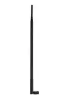
Whip Antenna, 868MHz to 870MHz, 1.9 VSWR, 3.2dBi Gain, 50ohm, Linear Polarisation, SMA Connector
⚠️ Reference pricing provided. In case of supply shortages, we will connect you with our trusted procurement partners to ensure your project's continuity.
- Manufacturer: TAOGLAS
- Product type:
- Antenna Type:Whip; Frequency Min:868MHz; Frequency Max:870MHz; Antenna Mounting:SMA Connector; Gain:3.2dBi; VSWR:1.9; Input Power:10W; Input Impedance:50ohm; Antenna Polarisation:Linear;
- Gain: 3.2dBi
- SVHC: To Be Advised
- VSWR: 1.9
- Input Power: 10W
- Antenna Type: Whip
- Frequency Max: 870MHz
- Frequency Min: 868MHz
- Product Range: -
- Input Impedance: 50ohm
- Antenna Mounting: SMA Connector
- Antenna Polarisation: Linear
| Delivery and price | |
|---|---|
| Units per pack | 250 |
| Price | 8.13 € |
| Current stock | 10+ |
| Lead time | 30 days |
Datasheet

## **SPECIFICATION**

Part No. : **TI.18.3113**

- Product Name  : 3dBi 868MHz ISM Band Dipole Terminal Antenna, SMA(M) Hinged Connector

- Feature : High efficiency dipole terminal antenna ROHS compliant

SPE-11-8-013/G/ZL      Page 1 of 22

## **1. Introduction**

TI.18 is high performance 868MHz ISM band dipole omni-directional antenna. The SMA connector is for general purpose used and the hinged design enables the antenna to be positioned at its most suitable angle.

For a lot of antenna applications, such as Wi-Fi Hotspot or cellular Pico-cell, the antenna of the operator’s device and the antenna of the user’s remote device are not on the same horizontal level. So rather than having the usual dipole antenna with dumbbell shape radiation pattern in the E-plane cross-section, we have designed this antenna with butterfly shape radiation pattern. This way, the best radiation direction of TI.18 will be more pointed to the remote user.

## **2. Specification**

|ELECTRICAL<br>~~[~~|ELECTRICAL<br>~~[~~|
|---|---|
|Frequency|868~870MHz|
|Peak Gain (bend)|3.2dBi|
|Peak Gain (straight)|3.2dBi|
|Average Gain (bend)|-0.3dBi|
|Average Gain (straight)|-0.3dBi|
|Efficiency (bend)|92%|
|Efficiency (straight)|93%|
|Impedance|50Ω|
|VSWR|<1.9 : 1|
|Polarization|Linear|
|Radiation Pattern|Omni|
|Input Power|10 W|
|MECHANICAL<br>~~Lo~~||
|Antenna Length|389±5 mm|
|Antenna Diameter|13±0.5 mm|
|Casing|TPU|
|Connector|SMA Male|
|ENVIRONMENTAL<br>~~Lo~~||
|Temperature Range|-40°C to 85°C|
|Humidity|Non-condensing 65°C 95% RH|


SPE-11-8-013/G/ZL      Page 2 of 22

## **3. Antenna S11 Properties**

## **3.1 Return Loss**

**==> picture [458 x 614] intentionally omitted <==**

**----- Start of picture text -----**<br>
0<br>-2 PEE<br>-4<br>-6<br>-8<br>-10<br>-12<br>bend<br>straight<br>-14<br>-16<br>700 800 900 1000 1100<br>3.2 VSWR<br>10<br>9<br>8<br>7<br>6<br>5<br>4<br>bend<br>3<br>straight<br>2<br>1<br>700 800 900 1000 1100<br>Le<br>SPE-11-8-013/G/ZL      Page 3 of 22<br>(dBi)<br>**----- End of picture text -----**<br>


## **3.2 VSWR**

## **4. Antenna Free Space Radiation Properties**

## **4.1. 3D Radiation Efficiency**

**==> picture [403 x 234] intentionally omitted <==**

**----- Start of picture text -----**<br>
100<br>90<br>80<br>70<br>60<br>50<br>40<br>bend<br>30<br>straight<br>20<br>10<br>0<br>800 820 840 860 880 900 920 940<br>(%)<br>**----- End of picture text -----**<br>


## **4.2. Peak Gain**

**==> picture [417 x 248] intentionally omitted <==**

**----- Start of picture text -----**<br>
4<br>3<br>2<br>1<br>0<br>bend<br>-1<br>straight<br>-2<br>-3<br>-4<br>800 820 840 860 880 900 920 940<br>(dBi)<br>**----- End of picture text -----**<br>


SPE-11-8-013/G/ZL      Page 4 of 22

**4.3. Average Gain**

**==> picture [438 x 472] intentionally omitted <==**

**----- Start of picture text -----**<br>
0<br>-1<br>-2<br>-3<br>bend<br>-4<br>straight<br>-5<br>-6<br>aoe<br>800 820 840 860 880 900 920 940<br>Radiation Pattern of 90 Degree Bend Position<br>y<br>4 [a]<br>z<br>x<br>(dBi)<br>**----- End of picture text -----**<br>


- **4.4. Radiation Pattern of 90 Degree Bend Position**

SPE-11-8-013/G/ZL      Page 5 of 22

## **4.4.1 3D Radiation Pattern**

## **XZ Plane Radiation**

**==> picture [284 x 260] intentionally omitted <==**

**----- Start of picture text -----**<br>
0<br>5<br>330 0 Lt| 30<br>-5<br>o te,<br>-10<br>O RME<br>300 -15 60<br>BQO -20 I><br>-25<br>-30<br>270 -35 90<br>240 120<br>ASH I ROG<br>SS I  RH<br>868MHz<br>SST C AT\ _ 870MHz<br>210 150<br>C CA S<br>180<br>(Unit : dBi)<br>**----- End of picture text -----**<br>


SPE-11-8-013/G/ZL      Page 6 of 22

## **XY Plane Radiation**

**==> picture [309 x 265] intentionally omitted <==**

**----- Start of picture text -----**<br>
0<br>5<br>330 Sunny, 0 30<br>-5<br>S -10 e,<br>300 SI -15 LO 60<br>-20<br>-25<br>-30<br>270 -35 90<br>————— pf<br>aes Ss 6 SS Sa<br>Lee \S Sen<br>868MHz<br>240 120<br>O S T = 870MHz<br>T T R<br>210 150<br>QT<br>180<br>(Uni t : dB<br>**----- End of picture text -----**<br>


## **4.4.4 Radiation at 45 Degree from XY Plane**

**==> picture [298 x 240] intentionally omitted <==**

**----- Start of picture text -----**<br>
5<br>330 0 30<br>-5<br>SETRR<br>-10<br>300 -15 60<br>PR -20 O M.<br>-25<br>-30<br>270 -35 90<br>SS —— _ samen<br>(Ee m e SSS<br>240 \ PALI T QO? 120<br>SMT NO<br>868MHz<br>CT A RY _<br>SALT VS = 870MHz<br>210 150<br>180<br>(Unit : dBi)<br>**----- End of picture text -----**<br>


SPE-11-8-013/G/ZL      Page 7 of 22

## **4.5. Radiation Pattern of 180 Degree Straight Position**

**==> picture [73 x 110] intentionally omitted <==**

**----- Start of picture text -----**<br>
y<br>z<br>x<br>**----- End of picture text -----**<br>


## **4.5.1 3D Radiation Pattern**

SPE-11-8-013/G/ZL      Page 8 of 22

## **XZ Plane Radiation**

**==> picture [291 x 267] intentionally omitted <==**

**----- Start of picture text -----**<br>
0<br>5<br>330 0 30<br>co te -5<br>-10<br>p os Hi elke<br>300 KY S -15 A TE 60<br>-20<br>EM E<br>BERR -25 A  TX<br>PIES ZZ oY<br>-30<br>SESS U e<br>270 -35 90<br>NS ee<br>INEZ SS<br>240 120<br>SUTI N SSS<br>S R R<br>868MHz<br>AUATIINGS Oe, 870MHz<br>210 150<br>THro Eo S =<br>180<br>(Unit : dBi)<br>**----- End of picture text -----**<br>


## **XY Plane Radiation**

**==> picture [317 x 277] intentionally omitted <==**

**----- Start of picture text -----**<br>
0<br>5<br>330 0 30<br>anneal<br>-5<br>soit<br>-10<br>300 O -15 M 60<br>AX SS r -20 en e Ny,<br>RRST -25 T R<br>FEES: li, Cee<br>-30<br>270 Bees -35 NG eee 90<br>sees7y, SAa<br>240 120<br>868MHz<br>870MHz<br>R S<br>210 150<br>SESS<br>HHS —<br>180<br>(Unit : dBi)<br>**----- End of picture text -----**<br>


SPE-11-8-013/G/ZL      Page 9 of 22

## **4.5.2 Radiation at 45 Degree from XY Plane**

**==> picture [342 x 275] intentionally omitted <==**

**----- Start of picture text -----**<br>
5<br>330 0 30<br>-5<br>S T R<br>-10<br>300 S -15 e oN 60<br>-20<br>-25<br>ZOQQWX Nyseat<br>FIERO -30 M Z Zeee |<br>270 -35 90<br>ioEESS 4 F SSS}<br>240 120<br>ees ij WS oe<br>Wo LT T QRS<br>_ 868MHz<br>— 870MHz<br>210 150<br>180<br>(Unit : dBi)<br>**----- End of picture text -----**<br>


SPE-11-8-013/G/ZL      Page 10 of 22

## **5. Ground Plane Effect**

Three ground setups are used to see the affect of positioning TI.18 close to ground -

1. Small Ground (15 x 9cm) – common size of CPE devices. TI.18 is mounted at the longer edge for testing.

2. Big Ground Edge (45 x 30cm) – simulate the effect of mounting antenna on a base station device. TI.18 is mounted at the centre of the longer edge.

3. Big Ground Centre (45 x 30cm) – simulate the effect of mounting antenna in a centre of a big ground plane, such as vehicle top.

SPE-11-8-013/G/ZL      Page 11 of 22

## **5.1. S11 Return Loss**

## **Bent**

**==> picture [448 x 235] intentionally omitted <==**

**----- Start of picture text -----**<br>
0 ee ee ee<br>-2 ee a ee i i<br>-4<br>-6<br>-8 eea en \Se7 A<br>-10 | | | | | | | NYRI f/f tt tl PP<br>a ee 2eee<br>-12 po| | | | | | | [| \NA[T/A] | | | tT fT fT ft<br>-14 |rp || || [|[| [|[| [| [| ft| INF[yy| fy| fTyf tete etye ythmeehm UT<br>-16 Yr| || || [|| || || [|| || || || [|[| [| [|| || || [| [|| fT| fTfT ff| |<br>-18-20-22 fFPYPF|r ||||| [||||| |||tf[| [|||tf [|[|||tf ft[||| fe|||| yyfT[||| f[||| fJ[|[| fTffT[| ff[||| |||| ft|tf| tTtTtT| fttytT| tftTft| teTTtTf tety| yyf ppp oSOL stand alonesmall gndbig gnd edgebig gnd centre<br>700 800 900 1000 1100<br>(dBi)<br>**----- End of picture text -----**<br>


## **Straight**

**==> picture [448 x 234] intentionally omitted <==**

**----- Start of picture text -----**<br>
0<br>-2<br>-4 FN eee Se<br>-6 aa seess\nOe, eel0h 2a<br>-8 (as\nA<br>-10 (OO<br>aS\Nn\n” A<br>-12 (a A<br>(a ss es en § A<br>-14-16 retrr+OO| |||Oe7;;| ||| es||| ee||| dT|| hooNA|| \ A)V/A?FTYZOC(QeFTtThrOOyyFT hr| hrTyyyhr hrCGryyyrTyyrTyyhr<br>-18 ret;r+ ||;; |;| | || |[| {||;yy 7| [fT| | fy| yy[Jyyy yy[yyyf_i<br>-20 rt;ry; || ;| || |;| || || || yy| | [yy| | - yy[J]yyyy7 yy]7 yf<br>-22 rt; | | | - | ft yy yy yy yyy<br>a A GG OO OO OO stand alone<br>-24 aCC small gnd<br>r+ CG GCG<br>-26 rf; | 7;; | | ; || | | | Th| hv|hv|hv [hvThvThvrPhvrThvrThrdThmrd] T| dhhvThv| hvFhvdT ht hr []l] [hU—] big gnd edge<br>a OG GC CG GG big gnd cent r e<br>-28 aOCOO CGC<br>700 800 900 1000 1100<br>(dBi)<br>**----- End of picture text -----**<br>


SPE-11-8-013/G/ZL      Page 12 of 22

## **5.2. VSWR**

## **Bent**

**==> picture [423 x 532] intentionally omitted <==**

**----- Start of picture text -----**<br>
6<br>5<br>4<br>3<br>stand al one<br>small gnd<br>2 big gnd edge<br>big gnd centre<br>Ve<br>1<br>700 800 900 1000 1100<br>6<br>5<br>4<br>3<br>stand alone<br>small gnd<br>2 big gnd e d ge<br>big gnd centre<br>1<br>700 800 900 1000 1100<br>**----- End of picture text -----**<br>


## **Straight**

SPE-11-8-013/G/ZL      Page 13 of 22

**5.3. Radiation Efficiency**

## **Bent**

**==> picture [466 x 500] intentionally omitted <==**

**----- Start of picture text -----**<br>
100<br>90<br>80<br>7<br>70<br>60<br>50<br>40<br>stand alone<br>30 small gnd<br>big gnd edge<br>20 big gnd center<br>10<br>0 =<br>820 830 840 850 860 870 880 890 900 910 920 (MHz)<br>Straight<br>100<br>90<br>80<br>70<br>60<br>50<br>40<br>stand alone<br>30 small gnd<br>big gnd edge<br>20 big gnd center<br>10<br>0 =<br>820 830 840 850 860 870 880 890 900 910 920 (MHz)<br>(%)<br>(%)<br>**----- End of picture text -----**<br>


SPE-11-8-013/G/ZL      Page 14 of 22

**5.4. Average Gain**

## **Bent**

**==> picture [452 x 550] intentionally omitted <==**

**----- Start of picture text -----**<br>
0<br>-1<br>-2<br>-3<br>stand alone<br>-4<br>small gnd<br>big gnd edge<br>big gnd center<br>-5<br>-6 a:7Ha<br>820 830 840 850 860 870 880 890 900 910 920<br>(MHz)<br>Straight<br>0<br>-1<br>SEE<br>-2<br>-3<br>stand alone<br>-4<br>small gnd<br>big gnd edge<br>big gnd center<br>-5<br>-6 ae=<br>820 830 840 850 860 870 880 890 900 910 920<br>(MHz)<br>(dBi)<br>(dBi)<br>**----- End of picture text -----**<br>


## **Straight**

SPE-11-8-013/G/ZL      Page 15 of 22

## **5.5. Peak Gain**

## **Bent**

**==> picture [447 x 539] intentionally omitted <==**

**----- Start of picture text -----**<br>
5<br>4<br>3<br>2<br>1<br>stand alone<br>small gnd<br>0 big gnd edge<br>big gnd center<br>-1<br>-2 ee<br>820 830 840 850 860 870 880 890 900 910 920 (MHz)<br>5<br>4<br>3<br>2<br>1<br>stand alone<br>small gnd<br>0 big gnd edge<br>big gnd center<br>-1<br>-2<br>820 830 840 850 860 870 880 890 900 910 920 (MHz)<br>(dBi)<br>(dBi)<br>**----- End of picture text -----**<br>


## **Straight**

SPE-11-8-013/G/ZL      Page 16 of 22

## **5.6. Radiation Pattern of 90 Degree Bend Position**

**XZ Plane Radiation**

**==> picture [408 x 575] intentionally omitted <==**

**----- Start of picture text -----**<br>
0<br>5<br>330 0 30<br>-5<br>So -10<br>300 -15 60<br>-20<br>oF -25<br>-30<br>270 -35 90<br>Ve ge .<br>p eg<br>240 120<br>S at<br>WIN S Sw<br>stand alone<br>Gi g<br>210 150 small gnd<br>S L<br>m e big gnd edge<br>180 big gnd center<br>(dBi)<br>XY Plane Radiation<br>0<br>5<br>330 0 30<br>-5<br>-10<br>300 -15 60<br>-20<br>-25<br>lp s<br>-30<br>270 fl fox -35 SSX 90<br>H e<br>C ee<br>240 120<br>stand alone<br>KO EE)<br>So<br>small gnd<br>210 150 bi g gnd edg<br>Pa bi g gnd cent<br>180<br>(dB i<br>**----- End of picture text -----**<br>


SPE-11-8-013/G/ZL      Page 17 of 22

## **5.6.3 Radiation at 45 Degree from XY Plane**

0

**==> picture [328 x 264] intentionally omitted <==**

**----- Start of picture text -----**<br>
5<br>330 0 30<br>-5<br>-10<br>300 -15 60<br>><br>-20<br>fake -25<br>-30<br>270 fi es -35 \ 90<br>AR ae<br>240 120<br>stand alone<br>small gnd<br>oy ET 210 150 big gnd edge<br>big gnd center<br>180<br>(dBi)<br>**----- End of picture text -----**<br>


SPE-11-8-013/G/ZL      Page 18 of 22

## **5.7. Radiation Pattern of 180 Degree Straight Position**

## **XZ Plane Radiation**

**==> picture [405 x 582] intentionally omitted <==**

**----- Start of picture text -----**<br>
0<br>5<br>330 0 30<br>-5<br>E<br>-10<br>300 -15 60<br>-20<br>¥.=~, -25<br>{) [<8]<br>-30<br>270 CE -35 E 90<br>\ [M] [ES]<br>240 120<br>stand alone<br>C es<br>small gnd<br>S S Ny<br>210 150 big gnd edge<br>Lf .=<br>big gnd center<br>180 (dBi)<br>XY Plane Radiation<br>0<br>5<br>330 0 30<br>-5<br>-10<br>300 -15 60<br>-20<br>JK 4 S<br>-25<br>-30<br>270 ge -35 e 90<br>240 120<br>stand alone<br>C a ss small gnd<br>Q E y big gnd edge<br>210 150<br>S s  yy big gnd center<br>e eeee<br>180 (dBi)<br>**----- End of picture text -----**<br>


SPE-11-8-013/G/ZL      Page 19 of 22

## **5.7.1 Radiation at 45 Degree from XY Plane**

**==> picture [334 x 281] intentionally omitted <==**

**----- Start of picture text -----**<br>
0<br>5<br>330 0 30<br>-5<br>JO -10<br>300 -15 60<br>-20<br>Y aac -25<br>-30<br>270 -35 90<br>fa gs<br>240 120<br>stand alone<br>small gnd<br>ay big gnd edge<br>210 150<br>oS<br>big gnd center<br>180<br>(dBi)<br>**----- End of picture text -----**<br>


SPE-11-8-013/G/ZL      Page 20 of 22

## **6. Mechanical Drawing (Unit: mm)**

SPE-11-8-013/G/ZL      Page 21 of 22

Taoglas makes no warranties based on the accuracy or completeness of the contents of this document and reserves the right to make changes to specifications and product descriptions at any time. Taoglas reserves all rights to this document and the information contained herein.

Reproduction, use or disclosure to third parties without express permission is strictly prohibited.

Copyright © Taoglas

SPE-11-8-013/G/ZL      Page 22 of 22
Updated at June 9, 2026
About Novapart
Novapart is a B2B electronic component broker specialising in stock shortages and cost reduction. We source hard-to-find parts and identify compliant alternatives across a catalogue of 410,000+ components from 500+ manufacturers.
Learn more →Stock Shortage Specialist
When a component is unavailable, discontinued or has an unacceptable lead time, we tap into our network of vetted European and Asian distributors to source what you need — without compromising on quality or traceability.
Request a quote →Compliant Alternatives
We identify pin-to-pin, electrically equivalent substitutes that meet the same certifications (RoHS, AEC-Q100, REACH) as your original specification — validated against datasheets, not just part numbers. Often at a lower cost.
BOM Analysis service →