
Image not available
Illustrative purposes only

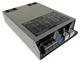
TGR1500-48
AC/DC Enclosed Power Supply (PSU), 1 Outputs, 1.5 kW, 48 V, 32 A
⚠️ Reference pricing provided. In case of supply shortages, we will connect you with our trusted procurement partners to ensure your project's continuity.
- Manufacturer: TIGER POWER SUPPLIES
- Product type: AC / DC Enclosed Power Supplies
- SVHC: To Be Advised
- Product Range: TGR1500 Series
- No. of Outputs: 1Outputs
- Output Power Max: 1.5kW
- Current, Output 4: -
- Input Voltage VAC: 85V AC to 264V AC
- Power Supply Output Type: Fixed
- Output Current - Output 1: 32A
- Output Current - Output 2: -
- Output Current - Output 3: -
- Output Voltage - Output 1: 48V
- Output Voltage - Output 2: -
- Output Voltage - Output 3: -
- Output Voltage - Output 4: -
- Power Supply Applications: -
| Delivery and price | |
|---|---|
| Units per pack | 3 |
| Price | 353.28 € |
| Current stock | 10+ |
| Lead time | 30 days |
Datasheet

**1500W Power Supply Series TGR1500-XX Series**

## **FEATURES**

- **Wide input voltage range 85 - 264VAC or 120 - 370VDC**

- **Accepts AC or DC input (dual-use of same terminal)**

- **Built-in active PFC function**

- **Operating ambient temperature range: -40** ℃ **to +70** ℃

- **High reliability, efficiency up to 94%**

- **Output short circuit, 5s constant-current, over-voltage, overtemperature protection**

- **Support 3+1 parallel redundancy, current sharing**

- **Operating up to 5000m altitude**

- **Fan speed automatic adjustable**

- **Safety according to IEC/EN/UL62368, EN/ES/IEC60601, IEC60335, GB4943**

_**TGR1500-XX series is one of Tiger Powers' enclosed AC-DC switching power supply. It features universal AC input and at the same time accepts DC input voltage, cost-effective, low no load power consumption, high efficiency, high reliability and double or reinforced insulation. These converters offer excellent EMC performance and meet IEC/EN/UL62368, EN/ES/IEC60601, IEC60335, GB4943 standards and they are widely used in areas of industrial, LED, street light control, electricity, security, telecommunications, smart home. etc.**_

**Selection Guide Nominal Output Voltage and Main Output Voltage Max. Capacitive Load Part No.* Output Power Current (Vo/Io) Adjustable Range Efficiency at (µF) (W) 230VAC (%) Typ. Vo1/Io1 Vo2/Io2 (V) Vo1 Vo1 Vo2 TGR1500-12 1510 12V/125A 12-14.4 92 40000** ~~ee|~~ **TGR1500-15** ~~ee~~ **1510 15V/100A** ~~ee a «\e0—Ww~~ **15-18** ~~JAANE~~ **92 20000** ~~ee~~ **TGR1500-24** ~~ee~~ **1510 24V/62.5A** ~~~~.~~ **24-28.8** ~~_4 ‘4~~ **94 10000** ~~ee~~ **TGR1500-27 1522 27V/56A 5V/2A 27-32.4 94** ~~iE~~ **8000 1000** ~~ee~~ **TGR1500-36** ~~ee~~ **1522 36V/42A** ~~ee~~ **36-43.2** ~~ee~~ **94 6000** ~~ee ee~~ **TGR1500-48** ~~ee~~ **1546** ~~ee~~ **48V/32A** ~~eee aee~~ **48-56** ~~**e**~~ **94** ~~e~~ **4000** ~~ee ee~~ **TGR1500-54 1522 54V/28A 54-58** ~~ee~~ **94 3000** ~~ee NC [| OS ee eee === |ONAN~~ **InputItem Specifications** ~~te~~ **Operating Conditions Min. Typ. Max. Unit** ~~|~~ **Rated input** ~~SN UUUUC—“;‘“CSC;*”S~~ **100 -- 240 VAC Input Voltage Range AC input 85 -- 264** ~~a~~ **DC input 120 -- 370 VDC** ~~| QAMT NS gl PRCT~~ **Input Voltage Frequency** ~~~ wR Q |~~ **47** ~~|~~ **--** ~~|~~ **63** ~~|~~ **Hz** ~~|~~ **115VAC -- -- 15.5 Input Current 230VAC -- -- 8** ~~————_——————E~~ **A 115VAC -- 16 20 Inrush Current Cold start 230VAC -- 32 40** ~~es Sree~~ **115VAC RoomPF** ≥ **0.99 Power Factor 230VAC temperature, full PF** ≥ **0.95** ~~Ee~~ ~~**load**~~ **Earth leakage current** < **0.5mA Leakage Current 240VAC** ~~po~~ **Touch current** < **0.5mA** ~~|~~ **Hot Plug** ~~__~~ **Unavailable** ~~pO~~

**www.TigerPowerSupplies.com**

1

**1500W Power Supply Series TGR1500-XX Series**

|**Output** **Specifications**<br>~~|~~|**Output** **Specifications**<br>~~|~~|**Output** **Specifications**<br>~~|~~|**Output** **Specifications**<br>~~|~~|**Output** **Specifications**<br>~~|~~|**Output** **Specifications**<br>~~|~~|**Output** **Specifications**<br>~~|~~|**Output** **Specifications**<br>~~|~~|
|---|---|---|---|---|---|---|---|
|**Item**<br>~~|~~<br>~~en~~|**Operating** **Conditions**<br>~~|~~<br>~~en~~||**Min.**<br>~~|~~<br>~~en~~|**Typ.**<br>~~|~~<br>~~en~~||**Max.**<br>~~|~~<br>~~en~~|**Unit**<br>~~|~~<br>~~en~~|
|**Output** **Voltage** **Accuracy**<br>~~en~~<br>~~SS~~<br>~~Se~~|**Full** **load**<br>~~en~~<br>~~SS~~|**Vo1**<br>~~en~~<br>~~SS~~|**--**<br>~~en~~|**±1.0**<br>~~en~~||**--**<br>~~en~~|**%**<br>~~en~~|
|||**Vo2**<br>~~SS~~|**--**|**±2.0**||**--**||
|**Line** **Regulation**<br>~~SeBe~~|**Rated** **load**<br>~~ee~~|**Vo1**|**--**|**±0.5**||**--**||
|||**Vo2**<br>~~ee~~|**--**<br>~~ee~~|**±1.0**<br>~~ee~~||**--**<br>~~ee~~||
|**Load** **Regulation**<br>~~SeBe~~|**0%-100%** **load**<br>~~ee~~|**Vo1**<br>~~ee~~|**--**<br>~~ee~~|**±0.5**<br>~~ee~~||**--**<br>~~ee~~||
|||**Vo2**<br>~~ee~~|**--**<br>~~ee~~<br>~~ee~~|**±3.0**<br>~~ee~~||**--**<br>~~ee~~||
|**Ripple** **&** **Noise***<br>~~Be~~|**20MHz** **bandwidth**<br>**(peak-to-peak** **value)**<br>~~ee~~<br>~~ee~~<br>~~es~~|**Vo1:12V/15V/24V/27V**<br>~~ee~~|**--**<br>~~ee~~<br>~~ee~~<br>~~ee~~|**--**<br>~~ee~~||**150**<br>~~ee~~|**mV**|
|||**Vo1:** **36V/48V**<br>~~ee~~<br>~~ee~~|**--**<br>~~ee~~<br>~~ee~~<br>~~ee~~<br>~~ee~~|**--**<br>~~ee~~<br>~~ee~~||**200**<br>~~ee~~<br>~~ee~~||
|||**Vo1:** **54V**<br>~~ee~~|**--**<br>~~ee~~<br>~~ee~~|**--**<br>~~ee~~||**250**<br>~~ee~~||
|||**Vo2:** **5V**<br>~~es~~|**--**<br>~~es~~|**--**<br>~~es~~||**100**<br>~~es~~||
|**Hold-up** **Time**<br>~~nS~~<br>~~pf~~|**Full** **input** **voltage**<br>~~es~~<br>~~nS~~<br>~~pf~~||**12**<br>~~es~~<br>~~nS~~<br>~~NS~~|**--**<br>~~es~~<br>~~nS~~<br>~~NS~~||**--**<br>~~es~~<br>~~nS~~<br>~~NS~~|**ms**<br>~~nS~~<br>~~NS~~|
|**Short** **Circuit** **Protection***<br>~~nS~~<br>~~pf~~|**After** **the** **short-circuit** **disappears,**<br>**the** **recover** **time** **<** **5s**<br>~~nS~~<br>~~pf~~||**Hiccup,** **self-recover**<br>~~nS~~<br>~~NS~~<br>~~ohSe” me~~|||||
|**Constant** **Current** **Protection***<br>~~pf~~<br>~~a~~|**230VAC**<br>~~pf ~~<br>~~a~~||**Constant** **current** **limit,**<br>**output** **voltage** **turn** **off** **after** **5s,** **self-recover**<br> ~~NS~~<br>~~a~~<br>~~ohSe” me~~|||||
|**Over** **Voltage** **Protection**<br>~~a~~<br>~~a=~~<br>~~ae~~<br>~~an~~<br>~~en~~<br>~~a~~<br>~~ae.~~<br>~~Oe~~|**12V**<br>~~a~~<br>~~a=~~<br>~~mb~~||≤**16.5V**<br>~~a~~<br>~~oh~~<br>~~a=~~<br>~~mb~~<br>~~Oe,~~||**Output** **voltage** **turn** **off,**<br>**re-power&** **PS_ON** **on** **for** **recover**<br>~~a~~<br>~~oh Se” me~~<br>~~a=~~|||
||**15V**<br>~~a=~~<br>~~ae~~<br>~~mb~~<br>~~a~~||≤**25.0V**<br>~~a=~~<br>~~ae~~<br>~~mb~~<br>~~Oe,~~|||||
||**24V**<br>~~a=~~<br>~~mb~~<br>~~an~~<br>~~a~~<br>~~Tam~~||≤**33.0V**<br>~~a=~~<br>~~mb~~<br>~~Oe ,~~<br>~~an~~<br>~~Sar~~|||||
||**27V**<br>~~a=~~<br>~~a~~<br>~~en~~<br>~~Tam~~<br>~~SS~~||≤**35.0V**<br>~~a=~~<br>~~en~~<br>~~Sar~~<br>~~BA~~|||||
||**36V**<br>~~a=~~<br>~~Tam ~~<br>~~a~~<br>~~SS~~<br>~~a~~||≤**48.0V**<br>~~a=~~<br> ~~Sar~~<br>~~a~~<br>~~BA~~<br>~~A~~|||||
||**48V**<br>~~a=~~<br>~~SS~~<br>~~ae.~~<br>~~a~~||≤**60.0V**<br>~~a=~~<br>~~BA~~<br>~~ae.~~<br>~~A~~|||||
||**54V**<br>~~a=~~<br>~~a~~<br>~~Oe OOS~~||≤**63.0V**<br>~~a=~~<br>~~A~~<br>~~OOS~~|||||
|**Over-**<br>**temperature**<br>~~**Protection**~~<br>~~eG~~<br>~~Oe~~<br>~~a~~|**Over-temperature** **protection** **activation**<br>~~eG~~<br>~~Oe OOS~~||**--**<br>~~eG~~<br>~~OOS~~||**--**<br>~~eG~~|**70**<br>~~eG~~|℃|
||**Over-temperature** **protection** **deactivation**<br>~~Oe OOS~~<br>~~eee~~||**50**<br>~~OOS~~<br>~~ne~~||**--**<br>~~ne~~|**--**<br>~~ne~~||
|~~**Protection**~~<br>**Minimum** **Load**<br>~~Oe~~<br>~~a~~<br>~~POeee~~|~~Oe OOS~~<br>~~eee~~<br>~~eee~~||**0**<br>~~OOS~~<br>~~ne~~<br>~~eee~~||**--**<br>~~ne~~<br>~~eee~~|**--**<br>~~ne~~<br>~~eee~~|**%**|
|**Dynamic** **Minimum** **Load**<br>~~a~~<br>~~POeee~~|~~eee~~<br>~~eee~~<br>~~OO~~||**10**<br>~~ne~~<br>~~eee~~||**--**<br>~~ne~~<br>~~eee~~|**--**<br>~~ne~~<br>~~eee~~||
|**Fan**<br>~~a~~<br>~~PO eee~~<br>~~COTS~~|~~eee ~~<br>~~eee~~<br>~~COTS~~<br>~~OO~~||**The** **fan** **speed** **is** **linearly** **adjusted** **and** **determined** **by**<br>**the** **output** **power** **and** **output** **voltage** **together**<br> ~~ne~~<br>~~eee~~<br>~~COTS~~|||||
|**Note:1.** ***The** **“Tip** **and** **barrel** **method”** **is** **used** **for** **ripple** **and** **noise** **test,** **output** **parallel** **47uF** **electrolytic** **capacitor** **and** **0.1uF** **ceramic** **capacitor,** **please** **refer** **to** **Enclosed**<br>**Switching** **Power** **Supply** **Application** **Notes** **for** **specific** **information;**<br>**2.*Over** **current** **protection** **is** **realized** **in** **constant** **current** **mode,** **see** **section** **2.6** **of** **the** **application** **manual** **below;**<br>**3.*For** **auxiliary** **short-circuit** **mode,** **refer** **to** **section** **2.7** **of** **the** **application** **manual** **below.**<br>~~OO~~||||||||


**2.*Over current protection is realized in constant current mode, see section 2.6 of the application manual below; 3.*For auxiliary short-circuit mode, refer to section 2.7 of the application manual below.**

|**General** **Specifications.**<br>~~RCA~~<br>~~WY)|~~<br>~~ee~~<br>~~NY(~~|**General** **Specifications.**<br>~~RCA~~<br>~~WY)|~~<br>~~ee~~<br>~~NY(~~|**General** **Specifications.**<br>~~RCA~~<br>~~WY)|~~<br>~~ee~~<br>~~NY(~~|**General** **Specifications.**<br>~~RCA~~<br>~~WY)|~~<br>~~ee~~<br>~~NY(~~|**General** **Specifications.**<br>~~RCA~~<br>~~WY)|~~<br>~~ee~~<br>~~NY(~~|**General** **Specifications.**<br>~~RCA~~<br>~~WY)|~~<br>~~ee~~<br>~~NY(~~|**General** **Specifications.**<br>~~RCA~~<br>~~WY)|~~<br>~~ee~~<br>~~NY(~~|**General** **Specifications.**<br>~~RCA~~<br>~~WY)|~~<br>~~ee~~<br>~~NY(~~|**General** **Specifications.**<br>~~RCA~~<br>~~WY)|~~<br>~~ee~~<br>~~NY(~~|
|---|---|---|---|---|---|---|---|---|
|**Item**<br>~~RCA~~<br>~~NY~~||**Operating** **Conditions**<br>~~RCA~~<br>~~WY)|~~<br>~~(~~|||**Min.**<br>~~RCA~~<br>~~ee~~|**Typ.**<br>~~RCA~~<br>~~ee~~|**Max.**<br>~~RCA~~<br>~~ee~~|**Unit**<br>~~RCA~~<br>~~ee~~|
|**Isolation** **Test**<br>~~NY~~|**Input** **-** **output**<br>~~NY~~|**Test** **for** **1min,** **leakage** **current** **<10mA**<br>~~WY) |~~<br>~~(~~|||**4000**<br>~~ee~~<br>~~ee~~|**--**<br>~~ee~~<br>~~**eee**~~|**--**<br>~~ee~~<br>~~**ee**~~|**VAC**<br>~~ee~~|
||**Input** **-**||||**2000**<br>~~ee~~<br>~~ee~~|**--**<br>~~ee~~<br>~~**eee**~~|**--**<br>~~ee~~<br>~~**ee**~~||
||**Output** **-**||||**1250**<br>~~ee~~<br>~~ee~~|**--**<br>~~ee~~<br>~~**eee**~~|**--**<br>~~ee~~<br>~~**ee**~~||
|**Insulation**<br>**Resistance**|**Input** **-** **output**|**Environment** **temperature:** **25±5**℃**Relative**<br>**humidity:** **<95%RH,** **non-condensing** **Testing**<br>**voltage:** **500VDC**|||**100**<br>~~ee~~|**--**<br>~~**eee** ~~<br>~~ee ee~~|**--**<br> ~~**ee**~~<br>~~ee~~|**M**Ω<br>~~ee~~|
||**Input** **-**|||||**--**<br>~~ee ee~~|**--**<br>~~ee~~||
||**Output** **-**|||||**--**<br>~~ee ee~~<br>~~ee~~|**--**<br>~~ee~~<br>~~ee~~||
|**Operating** **Temperature**<br>~~ee~~<br>~~ee~~||~~ee~~|||**-40**<br>~~ee~~|**--**<br>~~ee~~|**+70**<br>~~ee~~|℃|
|**Storage** **Temperature**<br>~~ee~~<br>~~ee~~||~~A~~|||**-40**<br>~~eee~~|**--**<br>~~eee~~|**+85**<br>~~ee~~||
|**Storage** **Humidity**<br>~~ee~~<br>~~ee~~||**Non-condensing**<br>~~A~~<br>~~ee~~<br> ~~—~~|||**10**<br>~~eee~~|**--**<br>~~eee~~|**95**<br>~~ee~~|**%RH**|
|**Operating** **Humidity**<br>~~ee~~<br>~~BS~~|||||**20**<br>~~eee~~<br>~~ee~~<br>~~—~~|**--**<br>~~eee~~<br>~~ee~~|**90**<br>~~ee~~<br>~~ee~~||
|**Switching** **Frequency**<br>~~ee~~<br>~~BS~~||**PFC** **@** **rated** **output**<br>~~A~~<br>~~ee~~<br> ~~—~~|||**--**<br>~~eee~~<br>~~ee~~<br>~~—~~|**65**<br>~~eee ~~<br>~~ee~~|**--**<br> ~~ee~~<br>~~ee~~|**kHz**|
|||**LLC** **@** **rated** **output**<br>~~ee~~<br> ~~—~~|||**--**<br>~~ee~~<br>~~—~~|**85**<br>~~ee~~|**--**<br>~~ee~~||
|**Power** **Derating**<br>~~BS~~<br>~~eT~~||**Operating**<br>**temperature**<br>~~ee~~<br> <br>~~eT~~|**12V/15V**<br>~~ee~~<br> ~~—~~<br>~~eT~~|**-40**℃ **to** **-30**℃<br>~~ee~~<br>~~— ~~<br>~~eT~~|**5**<br>~~ee~~<br> ~~—~~<br>~~eT~~|**--**<br>~~ee~~<br>~~eT~~|**--**<br>~~ee~~<br>~~eT~~|**%/**℃<br>~~eT~~|
|||||**-30**℃ **to** **+45**℃<br>~~eT~~|**0**<br>~~eT~~|**--**<br>~~eT~~|**--**<br>~~eT~~||


2

**1500W Power Supply Series TGR1500-XX Series**

**derating +45** ℃ **to +70** ℃ **1.6 -- -- -40** ℃ **to -30** ℃ **5 -- --** ~~es~~ **24V/27V/** ~~ee~~ **36/48V/ -30** ℃ **to +50** ℃ **0 -- -- 54V +50** ℃ **to +70** ℃ **2 -- --** ~~| ee ee~~ **85VAC - 100VAC 2 -- -- %/VAC Input voltage derating 120VDC - 200VDC 0.875 -- -- %/VDC** ~~ee FEES ee es es~~ **Safety according to IEC/EN/UL62368-1, EN/ Safety Standard ES/IEC60601-1, IEC60335-1, GB4943.1** ~~ee~~ **Safety Class** ~~eee~~ **CLASS** ~~eee~~ **I** ~~ees ee ee eses~~ **Input - output 2 × MOPP Isolation Level Input - 1 × MOPP** ~~ee~~ **Output - 1 × MOPP** ~~a~~ **MTBF MIL-HDBK-217F@25** ℃ > **250,000 h Mechanical Specifications Case Material SUS 304 Dimensions 250.0mm x 127.0mm x 40.5mm Weight 1800g (Typ.) Cooling Method Forced cooling (25CFM)**

## **Electromagnetic Compatibility (EMC)**

|**CE**<br>**CISPR32/EN55032** **CLASS** **B**|
|---|
|**Emissions**<br>**RE**<br>**CISPR32/EN55032** **CLASS** **B**|
|**Harmonic** **current**<br>**EN61000-3-2**<br>**CLASS** **A**|
|**ESD**<br>**IEC/EN61000-4-2**<br>**Contact** **±8KV/Air** **±15KV**<br>**perf.** **Criteria** **B**|
|**RS**<br>**IEC/EN61000-4-3**<br>**10V/m**<br>**perf.** **Criteria** **A**|
|**EFT**<br>**IEC/EN61000-4-4**<br>**±4KV**<br>**perf.** **Criteria** **B**|
|**Immunity**<br>**Surge**<br>**IEC/EN61000-4-5**<br>**line** **to** **line** **±2KV/line** **to** **PE** **±4KV**<br>**perf.** **Criteria** **B**|
|**CS**<br>**IEC/EN61000-4-6**<br>**10** **Vr.m.s**<br>**perf.** **Criteria** **A**|
|**Voltage** **dips,** **short** **Interruptions**<br>**and** **voltage** **variations**<br>**IEC/EN61000-4-11** **0%,** **70%**<br>**perf.** **Criteria** **B**|
|**Functional** **Specifications**<br>**Item**<br>**Operating** **Conditions**<br>**Min.**<br>**Typ.**<br>**Max.**<br>**Unit**<br>**Remote** **Control** **Switch**<br>**All** **input** **voltage** **range,** **all**<br>**load** **range**<br>**Power** **on**<br>**PS_ON** **(CN7,** **Pin6)** **and** **GND** **(CN7,** **Pin7/14)** **are**<br>**shorted**<br>**Power** **off**<br>**PS_ON** **(CN7** **Pin6)** **and** **GND** **(CN7** **Pin7/14)** **are**<br>**open**<br>**DC_OK** **Signal**<br>**All** **input** **voltage** **range,** **all**<br>**load** **range**<br>**Power** **on**<br>**2.5**<br>**--**<br>**5**<br>**V**<br>**Power** **off**<br>**--**<br>**--**<br>**0.5**<br>**Oring**<br>**Support** **direct** **parallel** **use,** **achieve** **3**<br>**+1** **parallel** **redundancy**<br>**Current** **Sharing** **Accuracy**<br>**Io** **>50%Io1**<br>**--**<br>**±5**<br>**--**<br>**%**<br>~~al EN~~<br>~~PA~~<br>~~i, | SD \~~<br>~~SS~~<br>~~a———————~~<br>~~ee~~<br>~~es~~<br>~~ee ——~~<br>~~ee~~<br>~~en~~|
|**LED** **Signal***<br>**Main** **output** **status**<br>**indication**<br>**Normal** **output**<br>**Green** **on**<br>**Abnormal** **output,** **protected**<br>**Red** **on**<br>**Power** **off** **(AC** **without** **input)**<br>**Light** **off**<br>**Remote** **Sense**<br>**Total** **compensate** **voltage,** **Vs+/Vs-** **(CN7** **Pin1/8)** **shorted** **to** **Vo**<br>**+/Vo-** **respectively**<br>**--**<br>**200**<br>**--**<br>**mV**<br>**SDA,** **SCL** **for** **I2C**<br>**Internal** **2.4k**Ω**pull-up** **resistor** **to** **internal** **3.3V**<br>**Note:** ***If** **the** **product** **is** **used** **in** **medical** **equipment,** **the** **terminal** **system** **should** **shield** **the** **LED** **signal** **light** **to** **meet** **the** **medical** **certification** **requirements** **that** **operators**<br>**should** **not** **see** **the** **indicator** **light** **after** **the** **product** **is** **installed.**<br>~~es~~<br>~~a~~<br>~~eess~~<br>~~ee~~<br>~~PC~~|


**www.TigerPowerSupplies.com**

3

**1500W Power Supply Series TGR1500-XX Series**

**Product Characteristic Curve**

**Note: 1. With an AC input voltage between 85 - 100VAC and a DC input between 120 - 200VDC the output power must be derated as per the temperature derating curves; 2. This product is suitable for use in natural air cooling environment. If used in closed environment, please consult our FAE.**

**www.TigerPowerSupplies.com**

4

**1500W Power Supply Series TGR1500-XX Series**

## **Dimensions and Recommended Layout**

**Note: 1. The bottom mounting hole of TGR1500 series products is based on the output side, which is compatible with our TGR1000 series products; 2. TGR1500 series products can be used with adapter plate: Compatible with the installation mode of mainstream 1500W products in the market. Please consult our FAE for EMC test operation instructions.**

## **Note:**

**1. For additional information on Product Packaging please contact us**

**2. Unless otherwise specified, parameters in this datasheet were measured under the conditions of Ta=25** ℃ **, humidity <75%RH with nominal input voltage and rated output load;**

**3. The room temperature derating of 5** ℃ **/1000m is needed for operating altitude greater than 2000m;**

**4. All index testing methods in this datasheet are based on our company corporate standards;**

**5. IWe can provide product customization service, please contact our technicians directly for specific information;**

**6. Products are related to laws and regulations: see "Features" and "EMC";**

**7. The out case needs to be connected to PE ( ) of system when the terminal equipment in operating;**

**8. Our products shall be classified according to ISO14001 and related environmental laws and regulations, and shall be handled by qualified units;**

**9. The power supply is considered a component which will be installed into a terminal equipment. All EMC tests should be confirmed with the final equipment. Please consult our FAE for EMC test operation instructions;**

**10. In the appearance dimension drawing, ±Vo represents the main output, ±S represents the auxiliary output, and the auxiliary output can be selected by the customer, which has no effect on the main output.**

**www.TigerPowerSupplies.com**

5

**1500W Power Supply Series**

**TGR1500-XX Series**

## **TGR1500-xx Power Supply Application Note**

## **Content**

|**1. **|**1.** **Overview**...........................................................................................................................................................................**7**|
|---|---|
|**2. **|**Function** **Manual**................................................................................................................................................................**11**|
||**2.1** **Input** **Requirements**................................................................................................................................................**11**|
||**2.2** **Output** **Requirements**.............................................................................................................................................**11**|
||**2.3** **Start-up** **timing**..........................................................................................................................................................**11**|
||**2.4** **Fan** **Speed** **Control**..................................................................................................................................................**12**|
||**2.5** **Output** **over-voltage** **protection(OVP)**..............................................................................................................**12**|
||**2.6** **Output** **over-current** **protection(OCP)**...............................................................................................................**13**|
||**2.7** **Output** **short** **circuit** **protection(SCP)**..................................................................................................................**13**|
||**2.8** **Over** **temperature** **protection(OTP)**...................................................................................................................**14**|
||**2.9** **Output** **power** **derating**.........................................................................................................................................**14**|
||**2.10** **Remote** **control**......................................................................................................................................................**14**|
||**2.11** **DC_OK** **Signal**......................................................................................................................................................... **15**|
||**2.12** **Remote** **compensation**.......................................................................................................................................**16**|
||**2.13** **Parallel** **operation**.................................................................................................................................................**17**|
||**2.13.1** **Redundancy**............................................................................................................................................... **17**|
||**2.13.2** **Current** **sharing**...........................................................................................................................................**17**|
||**2.14** **I2C** **communication** **address**...........................................................................................................................**19**|
|**3. **|**Installation** **requirements**..................................................................................................................................................**20**|
||**3.1** **Safety** **introduction**.................................................................................................................................................**20**|
||**3.2** **Safety** **requirements**................................................................................................................................................**20**|
||**3.3** **Installation** **method**.................................................................................................................................................**20**|
|**4. **|**Communication** **protocol**...............................................................................................................................................**22**|


**www.TigerPowerSupplies.com**

6

**1500W Power Supply Series TGR1500-XX Series**

## **1. Overview**

**==> picture [457 x 292] intentionally omitted <==**

**----- Start of picture text -----**<br>
7<br>7<br>Right side surface<br>|<br>Airflow<br>Top surface<br>\<br>Left side surface<br>6<br>4<br>5<br>Base surface<br>pe<br>3<br>1 2 2<br>**----- End of picture text -----**<br>


**Fig. 1: Appearance information of TGR1500-xx**

## **Overview description:**

**1. AC/DC input terminal (J1)**

**2. DC main output terminal (J2, J3)**

**3. Auxiliary road output terminal (CON5)**

**4. Signal connection press the terminal (CN7)**

**5. Green and red status display LED lights**

**6. Output voltage regulation resistor**

**7. Fans**

**www.TigerPowerSupplies.com**

7

**1500W Power Supply Series**

**TGR1500-XX Series**

## **1.1 AC/DC input terminal block (J1)**

**The input terminal J1, as a standard 3-pin fence welding terminal with upper cover, the center**

**spacing of the pins is 10mm.**

|**Pin**|**Features**|
|---|---|
|**L**|**Line** **(Phase)**|
|**N**|**Neutral**|
||**Ground/Earth**|


**Wire size: 12-22AWG Torque: 1.2N·m (max)**

## **1.2 Main DC output terminal (J2, J3)**

**The output terminal uses two standard screw lock type metal terminals, the pin spacing between each is 18mm.**

|**Pin**|**Features**|
|---|---|
|**+Vo**|**Main** **output** **+**|
|**-Vo**|**Main** **output** **-**|


**Torque: 2.3N·m**

**www.TigerPowerSupplies.com**

8

**1500W Power Supply Series**

**TGR1500-XX Series**

## **1.3 Auxiliary DC output terminal (CON5)**

**The auxiliary output terminal with a standard terminal of 2.5mm pitch.**

||**Pin**|**Function**|
|---|---|---|
||**-S**|**Auxiliary** **DC** **output** **-**|
||**+S**|**Auxiliary** **DC** **output** **+**|
|**CON5**|||


## **1.4 Signal port (CN7)**

|**Pin**|**Label**|**Features**|
|---|---|---|
|**1**|**VS+**|**Remote** **compensation** **positive**<br>**terminal**|
|**2**|**CURRENT** **SHARE**|**Current** **sharing** **bus**|
|**3**|**DC_OK**|**DC_OK** **Signal**|
|**4**|**SCL**|**I2C** **communication** **line**|
|**5**|**SDA**|**I2C** **communication** **line**|
|**6**|**PS_ON**|**Remote** **control** **signal**|
|**7**|**GND**|**Signal** **terminal** **reference** **ground**|
|**8**|**VS-**|**Remote** **compensation** **negative**<br>**terminal**|
|**9**|**ADDRESS0**|**ADDRESS** **code** **0**|
|**10**|**ADDRESS1**|**ADDRESS** **code** **1**|
|**11**|**ADDRESS2**|**ADDRESS** **code** **2**|
|**12**|**RXD**|**Serial** **communication**|
|**13**|**TXD**|**Serial** **communication**|
|**14**|**GND**|**Signal** **terminal** **reference** **ground**|


**Note: The reference ground of all pins on the signal terminal is pin7 and pin14.**

**www.TigerPowerSupplies.com**

9

**1500W Power Supply Series TGR1500-XX Series**

## **1.5 Green and red status display LED lights**

**==> picture [19 x 8] intentionally omitted <==**

**----- Start of picture text -----**<br>
LED<br>**----- End of picture text -----**<br>


**Two kinds of LED lights indicate difference working states of the power supply:**

|**Green** **LED**|**Red** **LED**|**Status**|
|---|---|---|
|**ON**|**OFF**|**Normal** **work**|
|**OFF**|**ON**|**Main** **or** **auxiliary** **road** **alarm**|
|**OFF**|**OFF**|**No** **AC** **input**|


## **1.6 Output voltage adjustment knob**

**Turn counterclockwise to increase output voltage**

**Changeable resistance**

|**Model**|**Rated** **Output** **Voltage**|**Adjustable** **Range** **Of** **Output** **Voltage**|
|---|---|---|
|**TGR1500-12**|**12V**|**12** **-** **14.4V**|
|**TGR1500-15**|**15V**|**15** **-** **18.0V**|
|**TGR1500-24**|**24V**|**24** **-** **28.8V**|
|**TGR1500-27**|**27V**|**27** **-** **32.4V**|
|**TGR1500-36**|**36V**|**36** **-** **43.2V**|
|**TGR1500-48**|**48V**|**48** **-** **56.0V**|
|**TGR1500-54**|**54V**|**54** **-** **58.0V**|


**www.TigerPowerSupplies.com**

10

**1500W Power Supply Series TGR1500-XX Series**

## **2. Function Manual**

## **2.1 Input requirements**

**The AC input voltage and DC input voltage must be within the defined voltage range (refer to data-sheet), otherwise the power supply may not work properly or even malfunction. The internal L and N line of the power module have been connected in series with a 250V 25A fuse. For better protection, it is recommended that customers use a circuit breaker not greater than 25A (Non-mandatory requirement).**

## **2.2 Output requirements**

**Main output**

**At any voltage value, the maximum output current and power must not exceed the rated/specified value. The**

**output current must not exceed the maximum output current value.**

**Auxiliary output**

**The auxiliary circuit supports a maximum current of 2A.**

## **2.3 Start-up timing**

|**Item**|**Operating** **Conditions**|**Operating** **Conditions**|**Min.**|**Typ.**|**Max.**|**Unit**|
|---|---|---|---|---|---|---|
|**Power-off** **Hold** **Time**|**Room** **temperature,**<br>**full** **load**|**115VAC**|**12**|**--**|**--**|**ms**|
|||**230VAC**|**12**|**--**|**--**||
|**Start** **Delay** **Time**|**230VAC,** **full** **load,** **25**℃||**--**|**--**|**3**|**s**|


**www.TigerPowerSupplies.com**

11

**1500W Power Supply Series TGR1500-XX Series**

## **2.4 Fan speed control**

**Fan speed is determined by output power and output voltage at the same time, refer to the following curve for**

**fan speed change.**

**==> picture [100 x 10] intentionally omitted <==**

**----- Start of picture text -----**<br>
Fig.1 Fig.2<br>**----- End of picture text -----**<br>


**Vo** : **Rated output voltage**

## **2.5 Output over-voltage protection (OVP)**

**Main output**

**The over-voltage protection function is to close the main output when the output voltage reaches the protection voltage value. When the main circuit over-voltage protection occurs, the main circuit output voltage of the module will be shut off, and the auxiliary circuit output will not be affected. The main circuit output can be restored after disconnecting the input power for at least 3 seconds.**

**In addition, it can be quickly restarted by the PS_ON signal:**

**Auxiliary output**

**When the auxiliary circuit voltage reaches 6.3VDC (maximum value), the auxiliary output will be in hiccup status, and the main output voltage turn off until the auxiliary output returns to normal after the fault is eliminated.**

**www.TigerPowerSupplies.com**

12

**1500W Power Supply Series TGR1500-XX Series**

## **2.6 Output constant-current protection (OCP)**

## ① **Main circuit overcurrent**

**If in CC load mode, when the current exceeds the constant current point, the output enters hiccup mode; when the over current state is released, the output returns to normal.**

**If in CR/CV load mode, the relationship among output current, voltage and resistance in shown in the following**

**curve:**

**==> picture [359 x 102] intentionally omitted <==**

**----- Start of picture text -----**<br>
Output voltage/V<br>V0<br>V1<br>Output resistance/ Ω<br>nae Fig.1 te R1 Fig.2R0<br>**----- End of picture text -----**<br>


**When the product enters the constant current state, the output state circulates as shown in Fig.1, working**

**for 5S and protecting for 3.5S, until the constant current state is released.**

**In that above Fig.2 the slope corresponding to section R1-R2 is the output current corresponding to**

**==> picture [203 x 39] intentionally omitted <==**

**When the auxiliary output current exceeds 120% (typ.) of the rated current, turn off the main output. After the secondary route overflows, the main route automatically recovers output.**

## **2.7 Output short circuit protection (SCP)**

**When the output is short-circuited, the power output in hiccup with interval 3.5s. After the short-circuit is removed, the power module will automatically return to normal, and the auxiliary output will not be affected.**

**When the auxiliary circuit output is short-circuited, the main circuit without output.**

**www.TigerPowerSupplies.com**

13

**1500W Power Supply Series TGR1500-XX Series**

## **2.8 Over-temperature protection (OTP)**

**When the ambient temperature of the power supply exceeds the rated temperature for a period of time, the power supply will be turned off and the power supply will resume normal operation after the ambient temperature drops to the set value.**

## **2.9 Output power derating**

**When the input voltage is greater than 100VAC (or 200VDC), only need to derate according to the temperature derating curve.**

**When the input voltage is lower than 100VAC (or 200VDC), the output power will be derated according**

**to the following input voltage derating curve after temperature derating.**

## **2.10 Remote control**

**www.TigerPowerSupplies.com**

14

**1500W Power Supply Series TGR1500-XX Series**

|**PS_ON** **(Pin6)** **and** **GND** **(Pin7or** **Pin14)**|**Output** **Status**|
|---|---|
|**Short-Circuit**|**Output** **on**|
|**Pin** **floating**|**Output** **off**|


**If the input terminal of the power module has been connected to a power source, the PS_ON signal pin can be**

**used to control the on and off of the main output, and the PS_ON signal does not affect the output voltage of the auxiliary circuit.**

**Note: The internal PS_ON input impedance of the module is 5.1K.**

## **2.11 DC_OK signal**

**The DC_OK signal is used to monitor whether the power supply is working normally, and the signal is at Pin3 of the signal terminal CN7.**

**Note: When the DC_OK signal is connected to the external circuit, the impedance of the external external circuit (i.e. between Pin3 and Pin7 or Pin14 of CN7) is not less than 10k** Ω **.**

|**DC_OK** **(Pin3)** **and** **GND** **(Pin7** **or** **Pin14)**|**Output** **State**|
|---|---|
|**2.5** **-** **5V**|**Output** **on**|
|**0** **-** **0.5V**|**Output** **off**|


**www.TigerPowerSupplies.com**

15

**1500W Power Supply Series TGR1500-XX Series**

## **2.12 Remote compensation**

## **Interleave**

## **Note:**

**1. Vs+ and Vs- cannot be shorted or reversed, otherwise the power module will be damaged.**

**2. Before powering on the product, please confirm whether the control signal connection terminal**

**(CN7) Pin6 (PS_ON) and Pin7 (GND) short-circuit jumper cap are connected. If not, the product without output. When the control signal connection terminal (CN7) of the product are external connected as a whole, please ensure that Pin6 and Pin7 (or Pin14) are short-circuit connected. Please refer to TGR1500-XX Series Power Supply Application Notes: 2.10 Remote control.**

**3. Pin 1 and pin 8 of the signal terminal CN7 can compensate the voltage drop on the output cable.**

**4. The remote compensation circuit can compensate up to 200mV cable voltage drop. This voltage**

**includes the sum of the cable drop connected to the output positive terminal and the output negative terminal.**

**5. If you need to use the remote compensation function, the signal pin needs to be connected with the load end with a twisted pair cable.**

**www.TigerPowerSupplies.com**

16

**1500W Power Supply Series TGR1500-XX Series**

## **2.13 Parallel operation**

## **2.13.1 Redundancy**

**The power module output can be connected in parallel to achieve redundancy, thereby improving system reliability. The maximum power of the redundant system needs to be derated to ensure that the redundant system can still meet the rated load requirements when a power supply module fails. The current common practice is to construct a redundant system by the N+1 method, that is, N+1 power supplies are connected in parallel, to support the maximum load current N*Iomax, where Iomax is the rated output current of each power supply. For example, the rated output current of each power supply is 40A, and 3+1 units are connected in parallel to construct a 3*40A=120A redundant system.**

**The power module supports 3+1 parallel redundant operation.**

**The ORing circuit is used inside the power module, and when any one of the power modules in the parallel fails, it will not affect the work of other power modules.**

**When used in parallel, the maximum load current cannot exceed the maximum output current of a single power supply module, otherwise the whole parallel power supply module will not start normally.**

## **2.13.2 Current sharing**

**Method 1** : **Current sharing bus and remote compensation lines are both connected.**

**For load line loss < 200mV, and the output voltage difference of each single module < 50mV, this type of**

**connection is recommended to obtain a better line-end output voltage and current sharing effect.**

**www.TigerPowerSupplies.com**

17

**1500W Power Supply Series TGR1500-XX Series**

**Method 2: Only the current sharing bus is connected, and the remote compensation is not**

## **connected.**

**For the load line loss > 200mV, or the output voltage difference of each single module cannot or does not need to be accurately adjusted to < 50mV, this type of connection is recommended to obtain a better current sharing effect of the parallel machine. In the same way, when the load loss is unknown or the current sharing fails to meet the specifications under the first connection method, it is recommended to replace it with this connected method. The wiring method of the current sharing function is shown in the figure below** :

**Note: 1. When using in parallel, the number of parallel modules cannot exceed 4.**

**2. Before powering on the product, please confirm whether the control signal connection terminal (CN7) Pin6**

**(PS_ON) and Pin7 (GND) short-circuit jumper cap are connected. If not, the product without output. When the control signal connection terminal (CN7) of the product are external connected as a whole, please ensure that Pin6 and Pin7 (or Pin14) are short-circuit connected. Please refer to TGR1500-XX Series Power Supply Application Notes: 2.10 Remote control.**

**When power modules work in parallel, there is an internal active current sharing circuit to ensure that the current between each module is balanced.**

**The active current sharing circuit adopts the automatic master-slave current sharing method. Each power module has a current sharing bus signal (CURRENT SHARE BUS). When working in parallel, the current sharing bus of all power modules must be connected together. The current-sharing bus signal is located at pin 2 of CN7.**

**www.TigerPowerSupplies.com**

18

**1500W Power Supply Series TGR1500-XX Series**

**The output voltage of each power module will affect the current sharing accuracy. The output voltage of the power module is the rated voltage ±50mV. In practical applications, if the output voltage value needs to be adjusted, the output voltage of all parallel power supply modules needs to be adjusted to the same voltage. The recommended voltage range: target voltage value ±50mV**

**After the output load of each power module is greater than 50% of the rated load, the current sharing accuracy should be ±5%. The current sharing calculation formula is:**

**==> picture [247 x 25] intentionally omitted <==**

**Iomax: the maximum output current value in parallel power supply modules. Iomin:**

**the minimum output current value in parallel power supply modules.**

## **2.14 I2C communication address**

**In the parallel system, if you need to identify the power module information, you need to set the I2C communication address for each parallel power module, and exchange data with the host computer through I2C. The setting of the communication address is determined by pins 9, 10 and 11 of the signal terminal CN7. When these three pins are short-circuited with pin 7 or 14 of CN7, it will be low level (L, voltage range: 0 - 1.31V). When disconnected, it is high level (H, voltage range: 1.99V - 3.3V). The specific address number is shown in the table**

## **below:**

|**ADDRESS** **2**|**ADDRESS** **1**|**ADDRESS** **0**|**Address** **number**|
|---|---|---|---|
|**L**|**L**|**L**|**0**|
|**L**|**L**|**H**|**1**|
|**L**|**H**|**L**|**2**|
|**L**|**H**|**H**|**3**|
|**H**|**L**|**L**|**4**|
|**H**|**L**|**H**|**5**|
|**H**|**H**|**L**|**6**|
|**H**|**H**|**H**|**7**|


**The internal pull-up resistance value of the power module is 10k** Ω **, and the external impedance can be matched according to the actual application to meet the high and low voltage range.**

**www.TigerPowerSupplies.com**

19

**1500W Power Supply Series TGR1500-XX Series**

## **3. Installation requirements**

## **3.1 Safety introduction**

## **Warning: Risk of electric shock During**

## **high voltage operating**

- **The power supply module is disconnected from the input DC or the AC power and placed for at least one minute before starting to operate it.**

- **When installing the input wire to the power module, please connect the ground terminal first, and then connect the L line and the N line.**

- **When removing the input wire, please remove the L wire and the N wire first, and then remove the ground wire.**

- **When disassembling, make sure that no objects fall into the power module.**

- **Pay attention to high temperature.**

- **After the power module is working in a high temperature environment, wait for its shell to cool down before operating.**

- **This product needs to be installed by professionals and needs to be used with other equipment.**

## **3.2 Safety requirements**

**When installing, pay attention to the primary side and the protective ground, the creep distance and the electrical clearance of the primary side and the secondary side refer to EN60601-1.**

## **3.3 Installation method**

**Standard mounting orientation:**

**www.TigerPowerSupplies.com**

20

**1500W Power Supply Series TGR1500-XX Series**

## **Position of mounting holes:**

**Note: The fan panel cannot be blocked by other objects, and a distance of at least 20mm must be maintained, otherwise it will affect the heat dissipation and performance of the power module.**

**www.TigerPowerSupplies.com**

21

**1500W Power Supply Series TGR1500-XX Series**

## **4. Communication protocol**

**The TGR1500-XX series power modules support standard communication protocols and manage and**

**monitor the power modules through I2C bus.**

|**Command**<br>**Code**<br>~~a~~|**Command** **Name**<br>~~a~~|**Access** **Type**<br>~~ee~~|**Data**<br>**Bytes**<br>~~ee~~|**Data** **Format**|**Description**|
|---|---|---|---|---|---|
|**0x9A**<br>~~a ~~<br>~~a~~<br>~~a~~|**PMB_MFR_MODEL**<br> ~~a~~|**Block** **Read**<br>~~ee~~|**32**<br>~~ee~~<br>~~ee~~|**ASCII**<br>~~ee~~|**Product** **model**|
|**0x8B**<br>~~a~~<br>~~a~~<br>~~a~~|**PMB_READ_VOUT**<br>~~ee~~|**Read** **Word**<br>~~ee~~|**2**<br>~~ee~~<br>~~ee~~|**Direct**<br>~~ee~~<br>~~ee~~|**Main** **circuit** **output**<br>**voltage** **(10mV)**<br>~~ee~~|
|**0x8C**<br>~~a~~<br>~~a~~|**PMB_READ_IOUT**<br>~~ee~~|**Read** **Word**<br>~~ee~~|**2**<br>~~ee~~<br>~~ee~~|**Direct**<br>~~ee~~<br>~~ee~~|**Main** **output** **current**<br>**(10mV)**<br>~~ee~~|
|**0x96**<br>~~a~~<br>~~re~~|**PMB_READ_POUT**<br>~~ee~~<br>~~ee.~~|**Read** **Word**<br>~~ee~~<br>~~ee.~~|**2**<br>~~ee~~<br>~~ee.~~|**Direct**<br>~~ee~~<br>~~ee.~~<br>~~ON~~|**Main** **output** **power**<br>**(10mV)**<br>~~ee~~<br>~~ee.~~<br>~~ONeee~~|
|**0xC4**<br>~~a~~<br>~~re~~|**PMB_MFR_AUX_VOUT**<br>~~ee~~<br>~~ee.~~|**Read** **Word**<br>~~ee~~<br>~~ee.~~|**2**<br>~~ee~~<br>~~ee.~~|**Direct**<br>~~ee~~<br>~~ee.~~<br>~~ON~~|**Auxiliary** **output**<br>**Voltage** **(10mV)**<br>~~ee~~<br>~~ee.~~<br>~~ONeee~~|
|**0xC5**<br>~~re~~<br>~~ee~~|**PMB_MFR_AUX_IOUT**<br>~~ee.~~<br>~~ee~~|**Read** **Word**<br>~~ee.~~<br>~~ee~~|**2**<br>~~ee.~~<br>~~ee~~|**Direct**<br>~~ee.~~<br>~~ON~~<br>~~ee~~|**Auxiliary** **output**<br>**current** **(10mV)**<br>~~ee.~~<br>~~ON eee~~<br>~~ee~~|
|**0xC7**<br>~~ee~~<br>~~a~~|**PMB_MFR_FAULT_BIT**<br>~~ee~~<br>~~ee~~|**Read** **Word**<br>~~ee~~<br>~~ee~~|**2**<br>~~ee~~<br>~~ee~~|**Bit** **Field**<br>~~ee~~<br>~~ee~~|**Fault** **status** **word**<br>~~ee~~<br>~~ee~~|


**www.TigerPowerSupplies.com**

22

**1500W Power Supply Series TGR1500-XX Series**

|**1500W** **Power** **Supply Series**<br>**TGR1500-XX** **Series**<br>EATIGER|**1500W** **Power** **Supply Series**<br>**TGR1500-XX** **Series**<br>EATIGER|
|---|---|
|**Describe** **Of** **Fault** **Status** **Through** **PMB_MFR_FAULT_BIT**||
|**Bit** **Segment**|**Description**|
|**BIT:** **0**|**0:** **Fan** **1** **normal**<br>**1:** **Fan** **1** **fault**|
|**BIT:** **1**|**0:** **Fan** **2** **normal**<br>**1:** **Fan** **2** **fault**|
|**BIT:** **2**|**0:** **Auxiliary** **output** **normal** **1:**<br>**Auxiliary** **output** **abnormal**|
|**BIT:** **3**|**0:** **No** **over-voltage** **in** **main** **circuit** **1:**<br>**Over-voltage** **in** **main** **circuit**|
|**BIT:** **4**|**0:** **No** **under-voltage** **in** **main** **circuit** **1:**<br>**Under-voltage** **in** **main** **circuit**|
|**BIT:** **5**|**0:** **No** **level** **1** **over-current** **in** **main** **circuit** **1:**<br>**Level** **1** **over-current** **in** **main** **circuit**|
|**BIT:** **6**|**0:** **No** **level** **2** **over-current** **in** **main** **circuit** **1:**<br>**level** **2** **over-current** **in** **main** **circuit**|
|**BIT:** **7**|**0:** **No** **level** **1** **over-load** **in** **main** **circuit** **1:**<br>**Level** **1** **over-load** **in** **main** **circuit**|
|**BIT:** **8**|**0:** **No** **level** **2** **over-load** **in** **main** **circuit** **1:**<br>**Level** **2** **over-load** **in** **main** **circuit**|
|**BIT:** **9**|**0:** **No** **level** **3** **over-load** **in** **main** **circuit** **1:**<br>**Level** **3** **over-load** **in** **main** **circuit**|
|**BIT:** **10**|**0:** **Normal** **temperature**<br>**1:** **Over-temperature** **and** **over-load**|
|**BIT:** **11**|**0:** **No** **short** **circuit** **in** **main** **circuit** **1:**<br>**Short** **circuit** **in** **main** **circuit**|
|**BIT:** **12**|**0:** **No** **hardware** **over-voltage** **in** **main** **circuit** **1:**<br>**Main** **circuit** **hardware** **over-voltage** **fault**|
|**BIT:** **13**|**0:** **No** **hardware** **under-voltage** **in** **main** **circuit** **1:**<br>**Main** **circuit** **hardware** **under-voltage** **fault**|
|**BIT:** **14**|**0:** **Pre-charge** **normal** **1:**<br>**Pre-charge** **fault**|
|**BIT:** **15**|**0:** **PFC** **soft** **start** **normal**<br>**1:** **PFC** **soft** **start** **fault**|


**www.TigerPowerSupplies.com**

23
Updated at June 4, 2026
About Novapart
Novapart is a B2B electronic component broker specialising in stock shortages and cost reduction. We source hard-to-find parts and identify compliant alternatives across a catalogue of 410,000+ components from 500+ manufacturers.
Learn more →Stock Shortage Specialist
When a component is unavailable, discontinued or has an unacceptable lead time, we tap into our network of vetted European and Asian distributors to source what you need — without compromising on quality or traceability.
Request a quote →Compliant Alternatives
We identify pin-to-pin, electrically equivalent substitutes that meet the same certifications (RoHS, AEC-Q100, REACH) as your original specification — validated against datasheets, not just part numbers. Often at a lower cost.
BOM Analysis service →