
Image not available
Illustrative purposes only

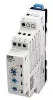
TDM-10
Analogue Timer, TD, Multifunction, 0.05 s, 240 h, 10 Ranges, 1 Changeover Relay
⚠️ Reference pricing provided. In case of supply shortages, we will connect you with our trusted procurement partners to ensure your project's continuity.
- Manufacturer: IMO PRECISION CONTROLS
- Product type: Analogue Timers - DIN Rail
- Time Max: 240h
- Time Min: 0.05s
- Timer Output: 1 Changeover Relay
- Product Range: TD
- Timer Functions: Multifunction
- Current Rating Nom: 8A
- Supply Voltage Max: 230VAC
- No. of Timing Ranges: 10Ranges
- Connection / Termination: Screw Terminals
| Delivery and price | |
|---|---|
| Units per pack | 10 |
| Price | 41.13 € |
| Current stock | 10+ |
| Lead time | 30 days |
Datasheet

## DIN Timers TD

17.5mm or 22.5mm DIN rail mounting Electronic Timers Wide coil operation, 24V to 320V AC/DC

Multi Time range / Multi function

ON-Delay, OFF-Delay, Asymetrical, Star/Delta versions

Perfect to fit in Modular Enclosure

Protection against over voltage and reverse polarity Self-Extinguishing plastic housing

## **Options and ordering codes**

**==> picture [125 x 102] intentionally omitted <==**

**----- Start of picture text -----**<br>
TD M10<br>DIN rail mount<br>TD<br>timers<br>Multi-function M10<br>Asymetical 5 function AS<br>Star/Delta 20-500ms SD1<br>**----- End of picture text -----**<br>


## **Specification**

|**Specification**||||
|---|---|---|---|
||**TDM10**<br>~~es~~<br>~~ee~~|**TDAS**<br>~~es~~<br>~~ee~~|**TDSD1**|
|Operation modes|A,B,C,D,E,F,G,H,I,K<br>~~ee~~<br>~~ee~~|ND,FD,NFD,Fon, Foff<br>~~ee~~<br>~~ee~~|Star Delta<br>~~ee~~<br>~~a~~|
|Time range|0.1sec - 10 days<br>~~ee~~<br>~~ee~~|0.1sec - 10 days<br>~~ee~~<br>~~ee~~|0.1sec - 10 days 1-30sec  /        20-500ms<br>Y<br>Y<br>~~ee~~<br>~~a~~|
|Accuracy|30ppm<br>~~ee ee~~<br>~~a~~|||
|e<br>g<br>atlo<br>v ylp<br>p<br>u<br>S|24-300V AC/DC, +/-10%, 45-65Hz||150-500VAC<br>45-65 Hz|
|Nominal power<br>consumption|24-320VDC max 1W ; 24VAC 2.5VA,<br>48VAC 4.46VA ; 110VAC 1.76 VA ; 220VAC 2.53 VA|||
|Input signal<br>Control contact must be<br>90% of A1-A2|Power On - contact control|Power On|Power On|
|Contact configuration|1 C/O contact<br>~~Pe~~|1 C/O contact|2 independent C/O contact|
|Control output|10A @ 250VAC / 3A @ 30VDC|||
|Life expectancy<br>Electrical<br>Mechanical|5 × 10⁴(5 A @ 250 V AC)<br>107operations|||
|Allowable ambient          Storage<br>temperature<br>Operating|-40 to +85 deg C<br>-25 to +70 deg C|||
|g<br>nitar PI|IP20|||
|sla<br>ni<br>m<br>re<br>T|2.5mm2Stranded, 4mm2Solid or 2x1.5mm2Solid|||
|Guarantee/Certification|2years/CE/UL/cUL|||


TDTimers 03/17

## DIN Timers TDM10

## Multi-function time delay

i Multi-time range

Compact design Universal voltage input 24~300V AC/DC Single module size

## **Specification**

## **Dimensions**

|**Specification**||
|---|---|
||**TDM10**|
|Adjustable values /<br>Time Range|1 second|
||10 second|
||100 second|
||1 minute|
||10 minute|
||1 hour|
||10 hour|
||100 hour|
||100 hour<br>1 day|
||10 day|
|Multiplier|0.1 - 0.2 - 0.3 - 0.4 - 0.5 - 0.6 - 0.7 - 0.8 - 0.9 - 1|


## **Indication Lights Legend**

|**LED**|**State**|**Description**|
|---|---|---|
|On/t|ON|Power ON|
||OFF|Power OFF|
|Relay<br>output|ON|Output relay energised|
||OFF|Output relay de-energised|
|M1, M2|M1, M2 are used to indicate which<br>function is currently used, see charts page<br>3 for more details||


## **Connections**

## **Time Settings**

Time range selector switch selects full scale time range. The t multiplier selector switch provides fine adjustment of time value, t, within the full scale time range. Selector switch positions are latched upon startup to avoid accidental changes during operation. Therefore changing selector switch positions have no effect when the device is operational. The below example shows how to set a t value.

**==> picture [393 x 86] intentionally omitted <==**

**----- Start of picture text -----**<br>
PownI reptu Raley<br>24..300V AC/DC<br>my i<br>O r<br>08poles T 4 U1 U2T<br>Time range t multiplier<br>**----- End of picture text -----**<br>


In the above figure: t=10h x 0.5 = 5 hour

Note: All the pot values are digitilised. Cannot be set to mid values.

TDTimers 03/17

## DIN Timer TDM10 continued

## **Mode functions**

## **A On Delay**

On application of supply voltage to terminals U1 and U2 (M2 LED flashing) the set time period t starts to run.  On completion of time t, the output Relay energises.  Power off reset

## **B Off Delay**

On application of supply voltage to terminals U1 and U2 (M1 LED flashing) the output Relay is energized and the time period t starts to run.  On completion of time t, the output Relay de-energises.  Power off reset

## **C On Delay with Control Signal**

T

Supply to the unit’s terminals U1 and U2 must be continuous (M1 LED On and M2 LED flashing).  The output Relay is initially de-energized.  Connection of U1 to T, triggers the timer and the output Relay is energised after the set time t has elapsed.

The Relay remains energized as long as there is a contact connection between U1 and T, opening the contact resets and de-energises the output Relay.

## **D Off Delay with Control Signal**

T

Supply to the unit’s terminals U1 and U2 must be continuous (M2 LED On and M1 LED flashing). Connection of U1 to T energizes the output Relay, then on opening the U1-T connection the set time period t starts running, when elapsed the output Relay is de-energized.  Reconnect of U1 to T restarts the time delay and the output Relay will remain energized if the time period has not elapsed.

## **E Rising edge triggered Off Delay**

T

Supply to the unit’s terminals U1 and U2 must be continuous (energizes asynchronous flashing of M1 and M2 LEDs).  On closure of contact between U1 and T the output Relay energizes and starts the set timing period t, after t has elapsed the output Relay is de-energized.  Changes to the T input will be ignored during the timing period t.

## **F Falling edge triggered Off Delay**

T

Supply to the unit’s terminals U1 and U2 must be continuous (synchronous flashing of M1 and M2 LEDs). On closure and opening of the connection between U1 and T the output Relay energizes and the set timing period t starts after this has elapsed the output Relay will de-energize.   Changes to the T input will be ignored during the timing period t.

## **G Off Flasher**

On application of supply voltage to U1 and U2 (synchronous flashing of M1 and M2 LEDs) starts the set timing period t with the output Relay initially de-energized, it is energised after the set time t has elapsed then de-energized for time period t.  The process repeats, until supply is removed.

## **H On and Off Delay with Control Input**

T

Supply to the unit’s terminals U1 and U2 must be continuous (asynchronous flashing of M1 and M2 LEDs).  On closure of a connection between U1 and T the set timing period t starts, when elapsed the output Relay energizes, after which on opening of this connection the timing period t starts again and output Relay is deenergized after the set time t has elapsed.

## **I Adjustable Pulse Output with Control Input**

T

Supply to the unit’s terminals U1 and U2 must be continuous (M1 LED flashing slowly).  Connection of U1 to T triggers the timer and energizes the output Relay, changes to the T input will be ignored during the time period t. The Relay is then de-energized after the set time t has elapsed.

## **K On Delay With memory**

T

Supply to the unit’s terminals U1 and U2 must be continuous (M2 LED flashing slowly).  With no connection between U1 and T on application of the supply output Relay will energize after time period t.  If there is a connection made between U1 and T during the time period t the count is delayed until such a time that this connection is opened, and then the count continues to relay energising.  Once the set time t has elapsed making and breaking the connection between U1 and T restarts the process.

TDTimers 03/17

## TDAS

## **Mode functions**

## **Indication Lights Legend**

## **Time Settings**

|**LED**<br>~~fe~~|**State**<br>~~fe~~|**Description**|
|---|---|---|
|On/t<br>~~fe~~<br>~~|~~|~~fe~~<br>~~|on~~|~~on~~<br>~~Poweron~~|
||~~| on~~|~~on~~<br>~~Power on~~<br>Power off|
|Relay Output||Output relay energized|
|||Output relay de-energized|
|M1, M2|~~On~~|~~On-Off delay mode~~|
||~~On~~<br>M2 flashing, M1 off|~~On-Off delay mode~~<br>On delaymode|
||M1 flashing, M2 off<br>-|Offdelaymode|
||-<br>Flash sequentially|On flasher mode|
||~~Flashsimultaneously~~|~~Off flasher mode~~|


## **Dimensions**

## **S ecification p**

||**TDAS**|
|---|---|
|Adjustable values /<br>Time Range|1 second|
||10 second|
||100 second|
||1 minute|
||10 minute|
||1 hour<br>10 hour|
||100 hour|
||1 day|
||10 day|
|Multiplier|0.1 - 0.2 - 0.3 - 0.4 - 0.5 - 0.6 - 0.7 - 0.8 - 0.9 - 1|


## **Connections**

**==> picture [54 x 33] intentionally omitted <==**

**----- Start of picture text -----**<br>
24-300V DC<br>24-300V AC<br>**----- End of picture text -----**<br>


TDTimers 03/17

## TDSD1

## **Mode Functions**

TDS1 star-delta starter is used for take-off starting method used in electrical motors. When energy applied from U1 and U2 terminals, star contacts will be energised until the end of the adjustable t  time. Later, at the end of the adjusted wait time t    , delta contacts » A-A will be energised until the device powered off.

## **Dimensions**

## **Connections**

**==> picture [16 x 12] intentionally omitted <==**

**----- Start of picture text -----**<br>
IMO<br>TDSD1<br>**----- End of picture text -----**<br>


**==> picture [45 x 8] intentionally omitted <==**

**----- Start of picture text -----**<br>
AC 150-500V<br>**----- End of picture text -----**<br>


TDTimers 03/17
Updated at February 9, 2023
About Novapart
Novapart is a B2B electronic component broker specialising in stock shortages and cost reduction. We source hard-to-find parts and identify compliant alternatives across a catalogue of 410,000+ components from 500+ manufacturers.
Learn more →Stock Shortage Specialist
When a component is unavailable, discontinued or has an unacceptable lead time, we tap into our network of vetted European and Asian distributors to source what you need — without compromising on quality or traceability.
Request a quote →Compliant Alternatives
We identify pin-to-pin, electrically equivalent substitutes that meet the same certifications (RoHS, AEC-Q100, REACH) as your original specification — validated against datasheets, not just part numbers. Often at a lower cost.
BOM Analysis service →