
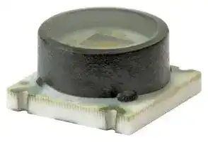


TBFLPNS150PGUCV
Pressure Sensor, 150 psi, Analogue, Gauge, 5 VDC, Low Profile, 600 µA
- Manufacturer: HONEYWELL
- Product type: Pressure Transducers
- Port Style: Low Profile
- Sensor Output: Analogue
- Supply Current: 600µA
- Voltage Rating: 5VDC
- Operating Pressure Max: 150psi
- Pressure Measurement Type: Gauge
| Delivery and price | |
|---|---|
| Units per pack | 1 |
| Price | 14.76 € |
| Current stock | 10+ |
| Lead time | 30 days |
**Basic Force Sensors** TBF Series, Compensated/Unamplified 1 bar to 10 bar | 100 kPa to 1 MPa | 15 psi to 150 psi **32315675** Millivolt Analog Output Issue A **Datasheet**

## **Datasheet** ~~LT~~

## **FEATURES**

- Cost-effective sensor with many options

- Compensated/unamplified

- Wide operating temperature range (0 °C to 50 °C [32 °F to 122 °F])

- Low power consumption allows for potential use in battery operated applications

- Stable offset voltage

- Not sensitive to mounting orientation

- Small package size [7 mm x 7 mm x 3,89 mm]

- RoHS2 compliance

## **POTENTIAL APPLICATIONS**

## **DESCRIPTION**

Honeywell’s TBF Series Force Sensors are small flush diaphragm pressure sensors designed for customers who require a simple device for applications where media compatibility and low trapped volume are important. The TBF Series has a precisely controlled diaphragm height, making these products useful in applications where force is applied by a flexible membrane to the sensor, such as infusion pumps. The sensor is internally unamplified, providing infinite resolution and allowing customers to do their own amplification in order to make use of the maximum resolution of the bare sensor output, leveraging any algorithm needed for the application. The sensor is internally temperature compensated and calibrated.

## **Medical**

- Drug delivery systems

- Infusion pumps

- Kidney dialysis machines

- Robotics

- Syringe pumps

- Wearables

## **PORTFOLIO**

The TBF Series joins the 1865 Series, FSG Series, FSS Series, FSS-SMT Series and FSA Series.

## **VALUE TO CUSTOMERS**

- Smallest package size in its class (7 mm x 7 mm x 3,89 mm) simplifies placement on crowded PCBs

- Widest pressure (1 bar to 10 bar |100 kPa to 1 MPa | 15 psi to 150 psi) enables choice of optimum pressure range to maximize sensitivity

- Many different pressure ranges improve resolution and system accuracy

- Tight accuracy specification of ±0.15 %FSS provides user with enhanced accuracy in the application

- Reliable supply chain

- Fast response for quotes and samples

- Designed to Six Sigma standards

- Manufacturing excellence

- Supports Lean manufacturing

Sensing and Productivity Solutions

**Basic Force Sensors, TBF Series, Compensated/Unamplified**

**Table 1. Absolute Maximum Ratings[1]**

**==> picture [542 x 75] intentionally omitted <==**

**----- Start of picture text -----**<br>
Characteristic Min. Max. Unit<br>Supply voltage (Vsupply) [2] -12.0 12.0 Vdc<br>Storage temperature -40 [-40] 125 [257] °C [°F]<br>Soldering time peak reflow temperature 10 s max. at 240 °C [464 °F]<br>**----- End of picture text -----**<br>


1Absolute maximum ratings are the extreme limits the device will withstand without damage.

2Incorrect application of supply voltage or ground to the wrong pin may cause electrical failure.

**Table 2. Operating Specifications**

**==> picture [542 x 112] intentionally omitted <==**

**----- Start of picture text -----**<br>
Characteristic Min.  Typ. Max. Unit<br>Supply voltage (Vsupply) [1, 2] 1.5 5.0 12.0 Vdc<br>Supply current (at 5.0 Vdc supply) - 0.6 1 mA<br>—<br>Operating temperature range [3] 0 [32] 50 [122] °C [°F]<br>—<br>Compensated temperature range [4] 0 [32] 50 [122] °C [°F]<br>Output resistance — 2.5 - kOhm<br>**----- End of picture text -----**<br>


- 1Ratiometricity of the sensor (the ability of the device output to scale to the supply voltage) is achieved within the specified operating voltage.

2Incorrect application of supply voltage or ground to the wrong pin may cause electrical failure.

3Operating temperature range: The temperature range over which the sensor will produce an output proportional to force.

4Compensated temperature range: The temperature range over which the sensor will produce an output proportional to force within the specified performance limits.

**Table 3. Environmental Specifications**

**==> picture [542 x 127] intentionally omitted <==**

**----- Start of picture text -----**<br>
Characteristic Parameter<br>Humidity   0 %RH to 95 %RH, non-condensing<br>Vibration 15 g, 10 Hz to 2 kHz<br>Shock 100 g, 6 ms duration<br>Life [1] 1 million pressure cycles min.<br>Solder reflow J-STD-020-D, MSL 1 (unlimited shelf life when stored at less than 30 °C and 85 %RH)<br>**----- End of picture text -----**<br>


1Life may vary depending on specific application in which sensor is utilized.

## **CAUTION**

## **PRODUCT SENSING SURFACE DAMAGE**

- The sensing surface of the sensor is composed of a tough silicone gel. Ensure that the sensing surface is not used with media incompatible with silicones.

- Ensure that the sensing surface does not come into contact with sharp or hard objects.

**Failure to comply with these instructions may result in product damage.**

## **NOTICE**

In order for the TBF Series sensors to provide a linear and repeatable output, ensure the entire top surface of the gel is exposed to a uniform pressure. The silicone gel allows direct contact with many liquids or the gel may be protected with a thin, compliant membrane.

**2** Sensing and Productivity Solutions

**Basic Force Sensors, TBF Series, Compensated/Unamplified**

## **Table 4. Sensor Pressure Type**

**==> picture [542 x 51] intentionally omitted <==**

**----- Start of picture text -----**<br>
Pressure Type Description<br>Output is proportional to the difference between applied pressure and atmospheric (ambient) pressure.<br>Gage<br>Reference pressure is atmospheric pressure.<br>**----- End of picture text -----**<br>


## **Table 5. Material Composition**

**==> picture [542 x 76] intentionally omitted <==**

**----- Start of picture text -----**<br>
Component Description<br>Cover high temperature polyamide<br>Substrate not exposed - protected by silicone gel<br>Sensing surface silicone gel<br>**----- End of picture text -----**<br>


**Table 6. Pressure Range Specifications for 1 bar to 10 bar**

**==> picture [541 x 222] intentionally omitted <==**

**----- Start of picture text -----**<br>
Thermal Effect  Thermal Effect<br>Pressure  Full Scale Span [3]<br>on Offset [4] on Span [5]<br>Range (mV/V) (%FSS) (%FSS)<br>Unit<br>0 ºC  0 ºC<br>Pmin. Pmax. Min. Nom. Max.  to  to<br>50 ºC  50 ºC<br>Gage<br>001BG 0 1 bar 4 ±0.5 ±0.3 4.90 5.10 5.30 ±1.0 ±1.0<br>1.6BG 0 1.6 bar 4 ±0.5 ±0.3 7.84 8.15 8.48 ±1.0 ±1.0<br>2.5BG 0 2.5 bar 8 ±0.5 ±0.15 6.10 6.35 6.59 ±1.0 ±0.75<br>004BG 0 4 bar 10 ±0.5 ±0.075 5.57 5.80 6.04 ±1.0 ±0.75<br>006BG 0 6 bar 17 ±0.5 ±0.075 5.08 5.30 5.54 ±0.75 ±0.75<br>010BG 0 10 bar 17 ±0.5 ±0.075 8.47 8.85 9.22 ±0.50 ±0.75<br>1<br>Pressure Accuracy  (%FSS) 2Offset (mV/V)<br>Order Code<br>(see Figure 1) Overpressure<br>Pressure Range<br>**----- End of picture text -----**<br>


1Accuracy: The maximum deviation in output from a Best Fit Straight Line (BFSL) fitted to the output measured over the pressure range at 25 °C [77 °F]. Includes all errors due to pressure non-linearity, pressure hysteresis, and non-repeatability.

2Offset: The output signal obtained when the reference pressure is applied to all available pressure ports. Also known as “null” or “zero”.

3Full Scale Span: The algebraic difference between the output signal measured at the maximum and minimum limits of the pressure range (see Figure 1).

4Thermal effect on offset: The deviation in offset due to changes in temperature over the compensated temperature range, relative to offset measured at 25 ºC.

5Thermal effect on span: The deviation in full scale span due to changes in temperature over the compensated temperature range, relative to full scale span measured at 25 ºC.

> Sensing and Productivity Solutions **3**

**Basic Force Sensors, TBF Series, Compensated/Unamplified**

**Table 7. Pressure Range Specifications for 100 kPa to 1 MPa**

**==> picture [542 x 544] intentionally omitted <==**

**----- Start of picture text -----**<br>
Thermal Effect  Thermal Effect<br>Pressure  Full Scale Span [3]<br>on Offset [4] on Span [5]<br>Range (mV/V)<br>(%FSS) (%FSS)<br>Unit<br>0 ºC  0 ºC<br>Pmin. Pmax. Min. Nom. Max.  to  to<br>50 ºC  50 ºC<br>Gage<br>100KG 0 100 kPa 400 ±0.5 ±0.3 4.90 5.10 5.30 ±1.0 ±1.0<br>160KG 0 160 kPa 400 ±0.5 ±0.3 7.84 8.15 8.48 ±1.0 ±1.0<br>250KG 0 250 kPa 800 ±0.5 ±0.15 6.10 6.35 6.59 ±1.0 ±0.75<br>400KG 0 400 kPa 1000 ±0.5 ±0.075 5.57 5.80 6.04 ±1.0 ±0.75<br>600KG 0 600 kPa 1700 ±0.5 ±0.075 5.08 5.30 5.54 ±0.75 ±0.75<br>001GG 0 1 MPa 1.70 ±0.5 ±0.075 8.47 8.85 9.22 ±0.50 ±0.75<br>1Accuracy: The maximum deviation in output from a Best Fit Straight Line (BFSL) fitted to the output measured over the pressure<br>range at 25 °C [77 °F]. Includes all errors due to pressure non-linearity, pressure hysteresis, and non-repeatability.<br>2Offset: The output signal obtained when the reference pressure is applied to all available pressure ports. Also known as “null” or<br>“zero”.<br>3Full Scale Span: The algebraic difference between the output signal measured at the maximum and minimum limits of the<br>pressure range (see Figure 1).<br>4Thermal effect on offset: The deviation in offset due to changes in temperature over the compensated temperature range, relative<br>to offset measured at 25 ºC.<br>5Thermal effect on span: The deviation in full scale span due to changes in temperature over the compensated temperature range,<br>relative to full scale span measured at 25 ºC.<br>Table 8. Pressure Range Specifications for 15 psi to 150 psi<br>Thermal Effect  Thermal Effect<br>Pressure  Full Scale Span [3]<br>on Offset [4] on Span [5]<br>Range (mV/V)<br>(%FSS) (%FSS)<br>0 ºC 0 ºC<br>Pmin. Pmax. Min. Nom. Max. to  to<br>50 ºC  50 ºC<br>Gage<br>015PG 0 15 psi 60 ±0.5 ±0.3 5.06 5.25 5.49 ±1.0 ±1.0<br>030PG 0 30 psi 115 ±0.5 ±0.15 5.05 5.25 5.45 ±1.0 ±0.75<br>060PG 0 60 psi 145 ±0.5 ±0.075 5.76 6.00 6.24 ±1.0 ±0.75<br>100PG 0 100 psi 245 ±0.5 ±0.075 5.83 6.10 6.36 ±0.75 ±0.75<br>150PG 0 150 psi 245 ±0.5 ±0.075 8.65 9.15 9.55 ±0.50 ±0.75<br>1<br>Pressure Accuracy  (%FSS) 2Offset (mV/V)<br>Order Code<br>(see Figure 1) Overpressure<br>Pressure Range<br>1<br>2<br>Unit<br>Pressure Accuracy  (%FSS) Offset (mV/V)<br>Order Code<br>(see Figure 1) Overpressure<br>Pressure Range<br>**----- End of picture text -----**<br>


1Accuracy: The maximum deviation in output from a Best Fit Straight Line (BFSL) fitted to the output measured over the pressure range at 25 °C [77 °F]. Includes all errors due to pressure non-linearity, pressure hysteresis, and non-repeatability.

2Offset: The output signal obtained when the reference pressure is applied to all available pressure ports. Also known as “null” or “zero”.

3Full Scale Span: The algebraic difference between the output signal measured at the maximum and minimum limits of the pressure range (see Figure 1).

4Thermal effect on offset: The deviation in offset due to changes in temperature over the compensated temperature range, relative to offset measured at 25 ºC.

5Thermal effect on span: The deviation in full scale span due to changes in temperature over the compensated temperature range, relative to full scale span measured at 25 ºC.

**4** Sensing and Productivity Solutions

**Basic Force Sensors, TBF Series, Compensated/Unamplified**

## **Figure 1. Nomenclature and Order Guide**

For example, **TBFLPNS150PGUCV** defines a TBF Series Basic Force Sensor, Leadless SMT package, low-profile pressure port, silicone gel interface, 0 psi to 150 psi gage pressure range, unamplified output, compensated, constant supply voltage.

**==> picture [520 x 246] intentionally omitted <==**

**----- Start of picture text -----**<br>
TBF    L    PN    S    150PG    U    C   V<br>Series Supply Voltage<br>TBF          Basic force sensor V Constant<br>Compensation<br>Package<br>L Leadless SMT (Surface Mount Technology) C Compensated<br>Output<br>I} | L EE<br>Pressure Port<br>U Unamplified<br>PN [Low-profile]<br>port Pressure Range<br>1 bar to 10 bar 100 kPa to 1 MPa 15 psi to 150 psi<br>Gage Gage Gage<br>001BG 0 bar to 1 bar 100KG 0 kPa to 100 kPa 015PG 0 psi to 15 psi<br>1.6BG 0 bar to 1.6 bar 160KG 0 kPa to 160 kPa 030PG  0 psi to 30 psi<br>Gel Coating Option 2.5BG  0 bar to 2.5 bar 250KG 0 kPa to 250 kPa 060PG  0 psi to 60 psi<br>S Silicone gel interface 004BG 0 bar to 4 bar 400KG 0 kPa to 400 kPa 100PG  0 psi to 100 psi<br>006BG  0 bar to 6 bar 600KG 0 kPa to 600 kPa 150PG 0 psi to 150 psi<br>010BG 0 bar to 10 bar 001GG 0 MPa to 1 MPa<br>**----- End of picture text -----**<br>


## **Figure 2. Leadless SMT Package Dimensional Drawings (For reference only: mm [in].)**

**==> picture [532 x 209] intentionally omitted <==**

**----- Start of picture text -----**<br>
Sensor Mounting Pad Layout<br>7 3,89 1<br>[0.276] [0.153] [0.039] 2,54<br>[0.100]<br>1<br>6<br>3,5<br>[0.138]        2,5 Typ.    2,50<br>[0.098]    [0.098]<br>7 6,5 5 2<br>[0.276] [0.26]<br>4 3 1,27<br>[0.050]<br>7,62<br>3,5 1,02 [0.300]<br>[MA [0.138] gid [0.040] ao,<br>Function Pin 1 Pin 2 Pin 3 Pin 4 Pin 5 Pin 6<br>————— analog Vs NC Vo- GND NC Vo+<br>**----- End of picture text -----**<br>


**5**

Sensing and Productivity Solutions

## **ADDITIONAL INFORMATION**

The following associated literature is available at sensing.honeywell.com:

- Product Range Guide

- Product Line Guide

- Product Installation Instructions

- Technical Information:

   - Output Signal Adjustment and Temperature Compensation for Honeywell Basic Force Sensors, TBF Series, Compensated/Unamplified

## **WARNING PERSONAL INJURY**

DO NOT USE these products as safety or emergency stop devices or in any other application where failure of the product could result in personal injury.

**Failure to comply with these instructions could result in death or serious injury.**

## **WARNING**

## **MISUSE OF DOCUMENTATION**

- The information presented in this datasheet is for reference only. Do not use this document as a product installation guide.

- Complete installation, operation, and maintenance information is provided in the instructions supplied with each product.

**Failure to comply with these instructions could result in death or serious injury.**

## **Warranty/Remedy**

## **Find out more**

Honeywell serves its customers through a worldwide network of sales offices, representatives and distributors. For application assistance, current specifications, pricing or name of the nearest Authorized Distributor, contact your local sales office.

Honeywell warrants goods of its manufacture as being free of defective materials and faulty workmanship. Honeywell’s standard product warranty applies unless agreed to otherwise by Honeywell in writing; please refer to your order acknowledgement or consult your local sales office for specific warranty details. If warranted goods are returned to Honeywell during the period of coverage, Honeywell will repair or replace, at its option, without charge those items it finds defective. **The foregoing is buyer’s sole remedy and is in lieu of all other warranties, expressed or implied, including those of merchantability and fitness for a particular purpose. In no event shall Honeywell be liable for consequential, special, or indirect damages.**

While we provide application assistance personally, through our literature and the Honeywell web site, it is up to the customer to determine the suitability of the product in the application.

Specifications may change without notice. The information we supply is believed to be accurate and reliable as of this printing. However, we assume no responsibility for its use.

To learn more about Honeywell Sensing and Productivity Solutions’ products, call **+1-815-235-6847** or **1-800-537-6945,** visit **sensing.honeywell.com** , or e-mail inquiries to **info.sc@honeywell.com**

Sensing and Productivity Solutions Honeywell 1985 Douglas Drive North Golden Valley, MN 55422

32315675-A-EN IL50 January 2016 © 2016 Honeywell International Inc. All rights reserved.

**honeywell.com**
Updated at February 9, 2023
Honeywell is a globally recognized leader in the design and manufacture of advanced sensing and switching solutions. Renowned for engineering components that deliver enhanced precision and ruggedness, Honeywell provides essential technologies for demanding applications across critical healthcare, aerospace, and industrial equipment. With a comprehensive portfolio built to address both basic and complex design challenges, the company stands at the forefront of reliable electronic component manufacturing. The core of our Honeywell offering is an extensive selection of high-performance sensors and transducers. This includes a robust lineup of pressure sensors and transducers engineered for accurate fluid and gas measurement in challenging environments. Furthermore, we provide a wide array of temperature sensors and specialized temperature sensing NTC thermistors designed for stable thermal management, alongside precision current sensors and load cells that deliver critical feedback for control systems. Beyond advanced sensing technology, Honeywell’s expertise extends to essential circuit protection and electromechanical components. Our selection encompasses power relays, thermal magnetic circuit breakers, and standard terminal blocks, ensuring safe and efficient power distribution. Whether integrating core components or sourcing specialized accessories, design engineers can rely on Honeywell for uncompromising quality and operational excellence.
About Novapart
Novapart is a B2B electronic component broker specialising in stock shortages and cost reduction. We source hard-to-find parts and identify compliant alternatives across a catalogue of 410,000+ components from 500+ manufacturers.
Learn more →Stock Shortage Specialist
When a component is unavailable, discontinued or has an unacceptable lead time, we tap into our network of vetted European and Asian distributors to source what you need — without compromising on quality or traceability.
Request a quote →Compliant Alternatives
We identify pin-to-pin, electrically equivalent substitutes that meet the same certifications (RoHS, AEC-Q100, REACH) as your original specification — validated against datasheets, not just part numbers. Often at a lower cost.
BOM Analysis service →