

T9AS5D12-18
RELAY, SPDT, 240VAC, 28VDC, 30A
- Manufacturer: TE CONNECTIVITY
- Product type: Power Relays
- Contact Configuration:SPDT; Coil Voltage:18VDC; Contact Current:20A; Product Range:T9A Series; Relay Mounting:Through Hole; Coil Type:Non Latching; Contact Voltage VAC 17M3067
| Delivery and price | |
|---|---|
| Units per pack | 1000 |
| Price | 4.38 € |
| Current stock | 10+ |
| Lead time | 30 days |
## Quick Reference Guide **INDUSTRIAL RELAYS** RELAYS, CONTACTORS & CIRCUIT BREAKERS
INDUSTRIAL /// QUICK REFERENCE GUIDE INDUSTRIAL RELAYS
**RELAYS, CONTACTORS & CIRCUIT BREAKERS**
TE Connectivity (TE) has extensive capabilities in the design and manufacture of relays and a broad portfolio of switching solutions for demanding, high performance applications. These relay products are remotely actuated to control electrical power flow by either interrupting or completing an electrical circuit.
Complying with standardized PCB footprints, TE offers a wide range of inrush current capabilities and addresses the complete spectrum of requirements for production lines, robotics, elevators, control panels, CNC machines, motion control systems, lighting, building systems, solar, HVAC, and an array of safety-critical applications. Through agency approved test labs, we ensure that our relays are tested to meet the expectations of the industry. Whether you are designing for harsh or indoor applications, TE delivers high quality relays from state-of-the-art production lines.
**==> picture [369 x 123] intentionally omitted <==**
**----- Start of picture text -----**<br>
SOLAR<br>HVAC l<br>— 7 aN ay<br>=) | = ig 2 See Rue<br>LIGHTING<br>**----- End of picture text -----**<br>
**==> picture [50 x 7] intentionally omitted <==**
**----- Start of picture text -----**<br>
ROBOTICS<br>**----- End of picture text -----**<br>
BUILDING SYSTEMS
INDUSTRIAL /// QUICK REFERENCE GUIDE INDUSTRIAL RELAYS
## CONTENTS
RELAYS, CONTACTORS & CIRCUIT BREAKERS
**==> picture [264 x 245] intentionally omitted <==**
**----- Start of picture text -----**<br>
||||
|---|---|---|
|Power PCB Relays up to 16A|......................................|4|
|Power PCB Relays up to 50A+|....................................|11|
|Force Guided Relays|.....................................................|14|
|Panel Plug-In Relays|.....................................................|16|
|Signal Relays|...................................................................|22|
|High Frequency Relays|................................................|27|
|Solid State Relays|..........................................................|28|
|Circuit Breakers|.............................................................|33|
|Transformers|...................................................................|36|
**----- End of picture text -----**<br>
## MOTION CONTROL
WHAT’S INSIDE
PAGE 3
**Power PCB Relays up to 16A** Relays, Contactors & Circuit Breakers
## Key Features
## **SCHRACK PE**
Low height 10.0mm Sensitive 200mW coil Mono-or bistable coil WG type available (IEC 60335-1)
**SCHRACK RE/REL PCJ** Miniature PCB relays Slim outline PCB area 200mm2 Sensitive coil 200mW Wash tight WG type available (IEC 60335-1) Ambient temperature up to 105°C
Footprint 2) see footnote below
||f<br>be 1s<br>L<br>Hi<br>Pregagaqedadndaas| he<br>14,|f<br>Heeseeeed<br>Pt TT Ty TT ae<br>is<br>CEES<br>[~~teat~~agdaq=4-4-4 Re<br>~~1,5~~|y<br>¥<br>+<br>Qoieeneneeeeet<br>|<br>1,05|
|---|---|---|---|
|Applications|Industrial electronics|PLC; Timers; I/O cards|Home applications|
||White goods|Temperature control|HVAC|
||Measurement and control|White goods||
|Contact Data||||
|Contact arrangement|1 form C (CO)|1 form A (NO)|1 form A (NO)|
|Rated voltage|250VAC|250VAC|250VAC|
|Rated current|5A (CO)|6/5A|3A/5A (WG type)|
||6A (NO)|||
|Switching power / Max. break|1250VA|1500/1250VA|750VA/1250VA (WG type)|
|Contact material|AgNi 90/10, AgSnO2|AgNi 0.15, AgNi 90/10|AgNi|
|Min. recommended|1) see footnote below|1) see footnote below|100mA at 5VDC|
|contact load||||
|Coil Data||||
|Magnetic system|DC, bistable|DC|DC|
|Rated coil voltage|3 to 48VDC|5 to 48VDC|5 to 24VDC|
|Rated coil power|200mW|200/360mW|200mW|
|Dielectric Strength||||
|Initial dielectric strength||||
|between open contacts|1000Vrms|1000Vrms|750Vrms|
|between contact and coil|4000Vrms|4000/3000Vrms|4000Vrms|
|between adjacent contacts||||
|Clearance/creepage||||
|between contact and coil|3.2/4mm|4/4mm|8/>8mm|
|Other Data||||
|Ambient temperature (max.)|+ 85°C|+70°C (RE)/ + 85°C (REL)|+ 85/ +105°C (WG type)|
|Category of environmental|RTII, RTIII|RTIII(RE), RTII(REL)|RTII, RTIII|
|protection IEC61810||||
|Terminal type|THT|THT|THT|
|Mounting|PCB|PCB|PCB|
|Dimensions|20x10x10mm|20x10x10.6mm/20.7x10.7x12mm|20.4x7x15mm|
|Accessories||||
|Link to datasheet|SCHRACK PE|SCHRACK RE|PCJ|
|||SCHRACK REL||
1) Recommended minimum load indication for contact material: AU and gold plated: 1mA at 6VDC; AgNi0.15 and AgNi90/10: 2) Footprint images are representative. For a complete selection, refer to the TE 10mA at 12VDC: AgCdO and AgSnO2: 100mA at 12VDC. Please contact technical support for detailed technical data. data sheet via the link above.
INDUSTRIAL /// QUICK REFERENCE GUIDE INDUSTRIAL RELAYS
**Power PCB Relays up to 16A** Relays, Contactors & Circuit Breakers
## Key Features
**PCH OJ/OJE/T77** Compact size Miniature size WG type available (IEC 60335-1) Sensitive coil 200mW TV-3 ratings for NO contact 4kV coil-contacts (OJ/OJT) Meet UL TV-5 ratings (OJT)
## **PCN/PCNH**
1 pole 3A/5A Only 5mm wide Allows high function/packaging density RoHS compliant (Directive 2002/95/EC)
**==> picture [466 x 479] intentionally omitted <==**
**----- Start of picture text -----**<br>
|||||||||
|---|---|---|---|---|---|---|---|
|4 – .05 DIA|v|
|(1.3)|.067|
|Footprint|2-b1.2t0.2|(1.71)|
|2) see footnote below|7|W02b01|5.10.1|saeco|
|Te+o2++Q----6--Fq-—--—-—-—--—---|/|Yedade9|H''|H:''|.300 (7.6 ±± .004 .1)|10fo)Ss)|CSSCECCOC|
|//|':|'TF|i|
|.500 ± .004|.1|00 ± .004|
|26.0.1 ||(12.7 ± .1)|(2.54 ± .1)|20,9"|
|1|
|Applications|Appliances|Appliances|PLC|
|HVAC|HVAC|Temperature control|
|Refrigerators, microwave ovens|Industrial control|I/O modules|
|Contact Data|
|Contact arrangement|1 form C (CO), 1 form A (NO)|1 form A (NO)|1 form A (NO)|
|Rated voltage|277VAC/30VDC|250VAC/28VDC|250VAC|
|Rated current|3/5/10A|3/5/8/10A|3A/5A|
|Switching power / Max. break|1400VA/150W (NO)|720 to 2500VA/|750VA /1250VA|
|850VA/90W (NC)|90 to 240W|
|Contact material|AgSnO2|Ag, AgCdO, AgSnO2|AgNi gold plated|
|Min. recommended|100mA at 5VDC|1) see footnote below|100mA at 5VDC|
|contact load|
|Coil Data|
|Magnetic system|DC, sensitive|DC, sensitive|DC|
|Rated coil voltage|3 to 48VDC|3 to 48VDC|3 to 24VDC|
|Rated coil power|200/400mW|200/250/450mW|100mW/120mW|
|Dielectric Strength|
|Initial dielectric strength|
|between open contacts|750Vrms|750/1000Vrms|750Vrms|
|between contact and coil|4000Vrms|3000/4000Vrms|3000Vrms|
|between adjacent contacts|
|Clearance/creepage|
|between contact and coil|1.6/3.2mm|1.6/3.2mm and 3.2/6.4mm|3.5mm|
|Other Data|
|Ambient temperature (max.)|+70°C (standard)/+85°C|up to 85°C|+85°C|
|(WG type)|
|Category of environmental|RTII, RTIII|RTII, RTIII|RTIII|
|protection IEC61810|
|Terminal type|THT|THT|THT|
|Mounting|PCB|PCB|PCB|
|Dimensions (lwh)|20x10x15.2mm|18.2x10.2x14.7mm|20x5x12.5mm|
|Accessories|
|Link to datasheet|PCH|OJ/OJE|PCN|
|T77|
**----- End of picture text -----**<br>
1) Recommended minimum load indication for contact material: AU and gold plated: 1mA at 6VDC; AgNi0.15 and AgNi90/10: 2) Footprint images are representative. For a complete selection, refer to the TE 10mA at 12VDC: AgCdO and AgSnO2: 100mA at 12VDC. Please contact technical support for detailed technical data. data sheet via the link above.
PAGE 5
**Power PCB Relays up to 16A** Relays, Contactors & Circuit Breakers
## Key Features
## **SCHRACK SNR**
5mm wide slim outline Strong coil pins for DIN-rail socket Allows high function/ packaging density
## **SCHRACK RYII**
Low height 12.3mm
Reinforced insulation Pinnings 3.2mm and 5mm
**SCHRACK MSR/T75**
High inrush currents with AgSnO contacts 4kV/8mm coil-contact Reinforced insulation
**==> picture [513 x 452] intentionally omitted <==**
**----- Start of picture text -----**<br>
||||||||||||
|---|---|---|---|---|---|---|---|---|---|---|
|Footprint|o13°°"|(2,5|-|2,54]|©1,3""'|
|2) see footnote below|mSL|OPT|sre|Y|\|t|{|Y|
|—Ei|[ pghotatotatathiad-deds|||qrecrerere|apepot=|comet|
|Her|olilo|oo"|5|Peary|TP TT TN|TPT|fa|PTT|AT|a|
|x|Her|AA|hea|Pee|NL|||
|or"|913"|e.¢|Asereretennei|iy|©ree3)|Pa)||S|
|1,9|19|iPs18,9||ar|3,2|2.9|iil|19|3,2|
|Applications|Interface technology|Interface technology|Interface technology|
|PLC, timers, Heating control|HVAC, PLC, Power supplies|HVAC, PLC, Power supplies|
|Domestic appliances|Domestic appliances|
|Contact Data|
|Contact arrangement|1 form C (CO), 1 form A (NO)|1 form C (CO), 1 form A (NO),|1 form C (CO)|
|1 from B (NC)|1 form A (NO)|
|Rated voltage|250VAC|250VAC|250VAC|
|Rated current|6A|8A|8/10A|
|Switching power / Max. break|1500VA|2000VA|2000VA|
|Contact material|AgSnO2 , AgSnO2 gold plated|AgNi0.15, AgSnO2, AgNi 0.15 gold plated|AgNi90/10, AgSnO2|
|Min. recommended|100mA at 12VDC|1) see footnote below|1) see footnote below|
|contact load|
|Coil Data|
|Magnetic system|DC|DC|DC|
|Rated coil voltage|5 to 48VDC|5 to 60VDC|3 to 60VDC|
|Rated coil power|170/217mW|(223 - 257)mW|(212-262)mW|
|Dielectric Strength|
|Initial dielectric strength|
|between open contacts|1000Vrms|1000Vrms|1000Vrms|
|between contact and coil|4000Vrms|5000Vrms|4000Vrms|
|between adjacent contacts|
|Clearance/creepage|
|between contact and coil|6/8mm|8/8mm|8/8mm|
|Other Data|
|Ambient temperature (max.)|+85°C|+70°C|+85°C|
|Category of environmental|RTIII|RTII, RTIII|RTII, RTIII|
|protection IEC61810|
|Terminal type|THT|THT, THR|THT|
|Mounting|PCB or on socket|PCB or on socket|PCB|
|Dimensions (lwh)|28x5x15mm|28.5x10.1x12.3mm|28.6x10x15mm|
|Accessories|DIN rail sockets|PCB sockets|
|Link to datasheet|SCHRACK SNR|SCHRACK RYII|SCHRACK MSR|
**----- End of picture text -----**<br>
1) Recommended minimum load indication for contact material: AU and gold plated: 1mA at 6VDC; AgNi0.15 and AgNi90/10: 10mA at 12VDC: AgCdO and AgSnO2: 100mA at 12VDC. Please contact technical support for detailed technical data.
2) Footprint images are representative. For a complete selection, refer to the TE data sheet via the link above.
INDUSTRIAL /// QUICK REFERENCE GUIDE INDUSTRIAL RELAYS
**Power PCB Relays up to 16A** Relays, Contactors & Circuit Breakers
## **SCHRACK RZ**
Key Features High performance version available Reinforced insulation High ambient temperature version (105°C) WG type available (IEC 60335-1) AgNi and AgSnO contact versions THR (reflow) version
## **SCHRACK RT**
DC and AC coil Mono-or bistable coil Reinforced insulation WG type available (IEC 60335-1) High ambient temperature version (105°C) THR (reflow) version Sensitive version Bifurcated contacts
## **SCHRACK RT INRUSH**
For inrush peak currents up to 80A Mono-or bistable coil Reinforced insulation WG type available (IEC 60335-1)
|Footprint<br>2) see footnote below|2) see footnote below|
|---|---|
|Applications|Household appliances|HVAC, Home automation,|Lighting applications, Movement|
|---|---|---|---|
||HVAC, Home automation|Machine control, Energy control|detectors, Motors control,|
||Machine control, Energy control|Switching cabinet, Interface modules|Domestic appliances|
|Contact Data||||
|Contact arrangement|1 form C (CO)|1 form C (CO), 1 from A (NO)|1 form C (CO)|
||1 form A (NO)|2 form C (CO), 2 form A (NO)|1 from A (NO)|
|Rated voltage|250VAC|250VAC|250VAC|
|Rated current|16A|2X8/16A|16A|
|Switching power / Max. break|4000VA|2X2000/4000VA|4000VA|
|Contact material|AgNi90/10, AgSnO2|AgNi90/10, AgSnO2|AgNi90/10, AgSnO2|
|Min. recommended|1) see footnote below|1) see footnote below|1) see footnote below|
|contact load||||
|Coil Data||||
|Magnetic system|DC|DC, AC, bistable|DC, bistable|
|Rated coil voltage|5 to 48VDC|5 to 110VDC/24 to 230VAC|5 to 11VDC|
|Rated coil power|400mW|400mW/0.75VA|400mW|
|Dielectric Strength||||
|Initial dielectric strength||||
|between open contacts|1000Vrms|1000Vrms|1000Vrms|
|between contact and coil|5000Vrms|5000Vrms|5000Vrms|
|between adjacent contacts||2500Vrms||
|Clearance/creepage||||
|between contact and coil|>10/10mm|>10/10mm|>10/10mm|
|Other Data||||
|Ambient temperature (max.)|+85°C|+75°C (AC type)|+85°C|
||+105°C (HOT type)|+85°C||
||+70°C (transparent cover type)|||
|Category of environmental|RTII, RTIII|RTII, RTIII|RTII|
|protection IEC61810||||
|Terminal type|THT|THT, THR (DC and AC type)|THT|
|Mounting|PCB|PCB or on socket|PCB or socket|
|Dimensions (lwh)|29x12.7x15.7mm|29x12.7x15.7mm|29x12.7x15.7mm|
|Accessories||PCB and DIN rail sockets||
|Link to datasheet|SCHRACK RZ|SCHRACK RT|SCHRACK RT INRUSH|
1) Recommended minimum load indication for contact material: AU and gold plated: 1mA at 6VDC; AgNi0.15 and AgNi90/10: 2) Footprint images are representative. For a complete selection, refer to the TE 10mA at 12VDC: AgCdO and AgSnO2: 100mA at 12VDC. Please contact technical support for detailed technical data. data sheet via the link above.
PAGE 7
**Power PCB Relays up to 16A** Relays, Contactors & Circuit Breakers
## Key Features
## **SCHRACK RTX**
Inrush peak currents up to 370A Bistable coil
Reinforced insulation
- EN60669-1
- 8A electronic ballast acc. UL508 1 1/2 HP motor load acc. UL508
## **SCHRACK RT iPOWER**
High Inrush peak currents up to 165A
- (20ms) and 800A (200 µ s) Mono-or bistable coil
RTS3T: 5A Electronic ballast acc. UL508 RTSET: 8A Electronic ballast acc. UL508 Test tab (manual operator) optional for RTT3T bistable versions
## **SCHRACK RP3SL**
Inrush peak currents up to 120A (20ms)
Mono-or bistable coil
Sealed version available
## Footprint
|Footprint|||||||||||||||:|:|:|:|:|:|:|:|:|:|:|:|:|:|:||||||||||
|---|---|---|---|---|---|---|---|---|---|---|---|---|---|---|---|---|---|---|---|---|---|---|---|---|---|---|---|---|---|---|---|---|---|---|---|---|---|---|
|Footprint<br>2) see footnote below|S0418-CM<br>ois"<br>~| ~~282~~<br>abetteey<br>eyee<br>PESOS<br>Pir<br>Is<br>R<br>e_les~~.0aso~~<br>~~20,3:~~<br>22,65%02||||||||||||||16 A, pinning 5 mm<br>ois"<br>bebetetetetp<br>acSdzsuansnant<br>boi toot<br>HEEEEE<br>~~eau~~ bonne<br>20,3°02|||||||||||||||o13""<br>SasneBBEESEC!<br>O°)<br>Po<br>LOTT <br>~~|~~<br>~~24~~<br>5,0||||||SasneBBEESEC!<br>Po<br> Per|SasneBBEESEC!<br>Poeit<br>Per<br>~~a~~||
|Applications|Lighting control systems||||||||||||||LED lighting systems, Lighting<br>Lighting control||||||||||||||||Lighting control||||||||
||Motion sensors||||||||||||||control, Movement detectors||||||control, Movement detectors|||||||||Motor control|||||Motor control||||
||Home automation applications||||Home automation applications||||||||||Filament and incandescent lamp<br>Building automation||||||||||||||||Building automation||||||||
||||||||||||||||Motor control||||||||||||||||||||||||
|Contact Data|||||||||||||||||||||||||||||||||||||||
|Contact arrangement|1 from A (NO)||||||||||||||1 from A (NO)|||||||||||||||1 form A, 1 NO|||||||||
|Rated voltage|250VAC||||||||||||||250VAC|||||||||||||||250VAC|||||||||
|Rated current|16A||||||||||||||16A|||||||||||||||16A|||||||||
|Switching power / Max. break|4000VA||||||||||||||4000VA|||||||||||||||4000VA|||||||||
|Contact material|W (pre-make contact) + AgSnO|||||||||W (pre-make contact) + AgSnO||W (pre-make contact) + AgSnO2|||W (pre-make contact) + AgSnO||||||||||W (pre-make contact) + AgSnO||W (pre-make contact) + AgSnO2<br>AgSnO2||||||||||||
||||||||||||||||AgSnO2||||||||||||||||||||||||
|Min. recommended|1) see footnote below|1) see footnote below|||||||||||||1) see footnote below|||||||||||||||100mA at 12VDC|||||||||
|contact load|||||||||||||||||||||||||||||||||||||||
|Coil Data|||||||||||||||||||||||||||||||||||||||
|Magnetic system|Bistable||||||||||||||DC, bistable|||||||||||||||DC|||||||||
|Rated coil voltage|5 to 48VDC||||||||||||||5 to 11VDC|||||||||||||||6 to 110VDC|||||||||
|Rated coil power|650mW/665mW||||||||||||||400mW|||||||||||||||500mW|500mW||||||||
|Dielectric Strength|||||||||||||||||||||||||||||||||||||||
|Initial dielectric strength|||||||||||||||||||||||||||||||||||||||
|between open contacts|1250Vrms||||||||||||||1250Vrms|||||||||||||||2000Vrms|||||||||
|between contact and coil|5000Vrms||||||||||||||5000Vrms|5000Vrms||||||||||||||4000Vrms|||||||||
|between adjacent contacts|||||||||||||||||||||||||||||||||||||||
|Clearance/creepage|||||||||||||||||||||||||||||||||||||||
|between contact and coil|min. 6/6mm||||||||||||||10/10mm|||||||||||||||8/8mm|||||||||
|Other Data|||||||||||||||||||||||||||||||||||||||
|Ambient temperature (max.)|+70°C||||||||||||||RTS3L/RTS3T +105°C, RTSET +85°C<br>+70°C||||||||||||||||||||||||
|Category of environmental|RTII||||||||||||||RTII|||||||||||||||RTII, RTIII||RTII, RTIII|||||||
|protection IEC61810|||||||||||||||||||||||||||||||||||||||
|Terminal type|THT||||||||||||||THT|||||||||||||||THT|||||||||
|Mounting|PCB||||||||||||||PCB|||||||||||||||PCB|||||||||
|Dimensions (lwh)|29.1x12.7x16mm||||||||||||||29x12.7x15.7mm (RTS3T),|||||||||||||29x12.7x15.7mm (RTS3T),||29x12.6x25.5mm|||||||||
||||||||||||||||29x12.7x16.0mm (RTS3L)||||29x12.7x16.0mm (RTS3L)||||||||||||||||||||
|Accessories|||||||||||||||||||||||||||||||||||||||
|Link to datasheet|SCHRACK RTX||||||||||||||SCHRACK RT IPOWER|SCHRACK RT IPOWER||||||||||||||SCHRACK RP3SL|||||||||
- 2) see footnote below
1) Recommended minimum load indication for contact material: AU and gold plated: 1mA at 6VDC; AgNi0.15 and AgNi90/10: 2) Footprint images are representative. For a complete selection, refer to the TE 10mA at 12VDC: AgCdO and AgSnO2: 100mA at 12VDC. Please contact technical support for detailed technical data. data sheet via the link above.
INDUSTRIAL /// QUICK REFERENCE GUIDE INDUSTRIAL RELAYS
**Power PCB Relays up to 16A** Relays, Contactors & Circuit Breakers
## **SCHRACK RP-2POLE 1.5MM**
Key Features 2 pole 8A 1.5mm contact gap per pole Creepage distance complies with IEC 60950 Sealed version available
**SCHRACK PB/PBH SCHRACK ORWH** Compact and simple design Compact relay with 1 form A and 1 gives high process security form C contact arrangement High ambient temperature 10A switching capacity version up to 105°C (PBH) WG type acc. IEC 60335-1
## Footprint
**==> picture [521 x 455] intentionally omitted <==**
**----- Start of picture text -----**<br>
||||||||||
|---|---|---|---|---|---|---|---|---|
|2) see footnote below|.236(6.0 ± ± .004 .1)|
|rye|-|.236 ± .004|
|(6.0 ± .1)|
|Foyret correEgret|ei|el|5 – .05 DIA|
|.079 ± .004|.48 ± .004|(1.3)|
|24|5,0|"||a)|5,0|6,25|1,25|(2.0 ± .1)|(12.2 ± .1)|
|Applications|Domestic appliances|White goods|Appliances|
|UPS|Small home appliances|HVAC|
|Solar Inverter|Heating temperature controllers|Emergency lighting|
|Contact Data|
|Contact arrangement|2 form A, 2 NO|1 form C (CO)|1 form C (CO)|
|1 form A (NO)|1 form A (NO)|
|Rated voltage|250VAC|250VAC|277VAC/28VDC|
|Rated current|8A|10A|10A|
|Switching power / Max. break|2000VA|2500VA|2770VA/360W|
|Contact material|AgSnO2|AgNi90/10, AgSnO|AgZnO, AgNi|
|Min. recommended|100mA at 12VDC|1) see footnote below|100mA at 5VDC|
|contact load|
|Coil Data|
|Magnetic system|DC|DC|DC|
|Rated coil voltage|5 to 110VDC|5 to 48VDC|5 to 24VDC|
|Rated coil power|780mW|360mW/500mW|360mW|
|Dielectric Strength|
|Initial dielectric strength|
|between open contacts|25000Vrms|1000Vrms|750Vrms|
|between contact and coil|5000Vrms|2500Vrms|1500Vrms|
|between adjacent contacts|300Vrms|
|Clearance/creepage|
|between contact and coil|7/8mm|3/4mm / 4/5mm|3.2mm|
|Other Data|
|Ambient temperature (max.)|+40°C|+85°C/+105°C|+85°C|
|Category of environmental|RTII, RTIII|RTII|RTII, RTIII|
|protection IEC61810|
|Terminal type|THT|THT|THT|
|Mounting|PCB|PCB|PCB|
|Dimensions (lwh)|29x12.6x25.5mm|15x15x20mm|19.0x15.5x15.8mm|
|Accessories|
|Link to datasheet|SCHRACK RP-2POLE 1.5MM|SCHRACK PB|SCHRACK ORWH|
|SCHRACK PBH|
**----- End of picture text -----**<br>
2) see footnote below
1) Recommended minimum load indication for contact material: AU and gold plated: 1mA at 6VDC; AgNi0.15 and AgNi90/10: 2) Footprint images are representative. For a complete selection, refer to the TE 10mA at 12VDC: AgCdO and AgSnO2: 100mA at 12VDC. Please contact technical support for detailed technical data. data sheet via the link above.
PAGE 9
**Power PCB Relays up to 50A+** Relays, Contactors & Circuit Breakers
Key Features
**Potter & Brumfield T9G** High breaking capacity
PCB and quick connect connections 4kV/8mm coil-contact Minimum board space (29mm x 21.5mm) UL-class F as standard
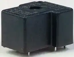
## **Potter & Brumfield T9A**
High breaking capacity
PCB and quick connect and chassis mount version UL-class F as standard Open version available
**Potter & Brumfield T9S/T9V** 1 pole 35A (T9S)/40A (T9V) Contact gap 1.5mm/1.8mm min. Ambient temperature up to 85°C at 35A Production in accordance to IEC 60335-1 RoHS compliant (Directive 2002/95/EC)
**==> picture [512 x 485] intentionally omitted <==**
**----- Start of picture text -----**<br>
||||||||||||||||||
|---|---|---|---|---|---|---|---|---|---|---|---|---|---|---|---|---|
|Footprint|max.|us|max.|2.49|.140 MAX.(3.56)|.250 MAX.(6.35)|21.78|
|2) see footnote below|i'1|joooaanen|11'|4Cali]+|aoe1hHi|(7.62)|+O|.300|||t|(2.54).100|ti9aoe|-|857|=>|iIV4tf3.43t|
|g|\|t|3|u|;|a)|15.48|{foo|
|Fi]adela4|IHi!|t|+Si'1g}|a}agaaa||8}ttUb|ddsitelLgH|(15.24)|44|.600|(12.7).500|Tt\|1|6|0|oe=|—||3.3359:03|
|.150|
|(3.81)|.550|
|11:78|:|18.|-|(13.97)(17.78).700|—|18.75|
|Applications|HVAC, Appliances|HVAC|Photovoltaic inverter|
|Industrial control|Appliances|Electrical vehicle loading stations|
|Energy management|Industrial controls|Electrical vehicle|
|Contact Data|
|Contact arrangement|1 form C (1 CO)|1 form C (1 CO)|1 form A (1NO)|
|1 form B (1 NC)|1 form B (1 NC)|
|1 form A (1 NO)|1 form A (1 NO)|
|Rated voltage|250VAC|250VAC|277VAC (1.5mm gap), 250VAC|
|(1.8mm gap)|
|Rated current|30A|30A|35A (T9S) , 40A (T9V)|
|Switching power / Max. break|7500VA|9695VA (T9S), 10000VA (T9V)|
|Contact material|AgSnO2|AgCdO, AgSnInO|AgNi|
|Min. recommended|1A at 12VAC/VDC|1A at 5VDC or 12VAC|1A at 5VDC/12VAC|
|contact load|
|Coil Data|
|Magnetic system|DC|DC|Monostable|
|Rated coil voltage|5 to 110VDC|6 to 48VDC|12VDC|
|Rated coil power|900mW|1W/900mW|2.25W|
|Dielectric Strength|
|Initial dielectric strength|
|between open contacts|1500Vrms|1500Vrms|2500Vrms|
|between contact and coil|4000Vrms|2500Vrms|4000Vrms|
|between adjacent contacts|
|Clearance/creepage|6.4mm / 9.5mm (UL)|
|between contact and coil|8mm / 8mm (IEC)|3.1/6.3mm|3/4mm|
|Other Data|
|Ambient temperature (max.)|+105°C|+85°C|+85°C|
|Category of environmental|RTII, RTIII|RT0, RTI, RTII, RTIII|RTII/RTIII|
|protection IEC61810|
|Terminal type|THT/Quick connect|THT/Quick connect|PCB|
|Mounting|PCB|PCB, panel mount|PCB|
|Dimensions (lwh)|29x21.5x15.7mm|32.3x27.4x20.4mm|32x27x20mm|
|Accessories|
|Link to datasheet|Potter & Brumfeld T9G|Potter & Brumfeld T9A|Potter & Brumfeld T9V|
|Potter & Brumfeld T9S|
**----- End of picture text -----**<br>
1) Recommended minimum load indication for contact material: AU and gold plated: 1mA at 6VDC; AgNi0.15 and AgNi90/10: 2) Footprint images are representative. For a complete selection, refer to the TE 10mA at 12VDC: AgCdO and AgSnO2: 100mA at 12VDC. Please contact technical support for detailed technical data. data sheet via the link above.
INDUSTRIAL /// QUICK REFERENCE GUIDE INDUSTRIAL RELAYS
**Power PCB Relays up to 50A+** Relays, Contactors & Circuit Breakers
Key Features
## **Potter & Brumfield T92**
Switching capacity 7500VA DC or AC coil 4kV/8mm coil-contact PCB or quick connect connections or chassis mount
## **PCF**
## **PCFN SOLAR**
Quick connect terminal for Specially designed to meet the load (PCF only) requirements for solar Height 26.5mm Contact gap 1.5mm/1.8mm min. Meet 4kV dielectric voltage 200mW hold power between coil and contact Ambient temperature 85°C
**==> picture [505 x 459] intentionally omitted <==**
**----- Start of picture text -----**<br>
||||||||||||||||
|---|---|---|---|---|---|---|---|---|---|---|---|---|---|---|
|Footprint2) see footnote below|(7.85).309|(14.86).585|(41.10)1.618|(4.70).185|2 – .071 DIA(1.8)|\|1.09(27.6 ± ± .008 .2)|
|.365|.244|
|(9.27)|(6.2)|.472 ± .008|
|(16.00).630|(25.40)1.000|.228(5.8)|(12.0 ± .2)|
|.203 TYP.(5.16)(4.12).162|||x|I-|.052 TYP.(1.32)|.072 TYP.(1.83)|2 – .063 DIA(1.6)|(12.0).472|;|(10.0).394|2x|O16|12,0_,|‘|10,0|
|Applications|HVAC|Applicances|Photovoltaic Inverter|
|Residential/commercial appliances|HVAC|
|Industrial controls|Office machines|
|Contact Data|
|Contact arrangement|2 form C (2 CO)|1 form A (1 NO)|1 form A (1 NO)|
|2 form A (2 NO)|
|Rated voltage|400VAC|250VAC|277VAC|
|Rated current|30A|25A|26A|
|Switching power / Max. break|7500VAC|6370VA|7200VA|
|Contact material|AgCdO, AgSnInO|Visit|TE.com|for more information|AgSnO2|
|Min. recommended|500mA (NO)/ 100mA (NC)|100mA at 5VDC|100mA at 5VDC|
|contact load|at 12VAC|
|Coil Data|
|Magnetic system|DC, AC|DC|DC|
|Rated coil voltage|5 to 110VDC/12 to 240VAC|6 to 24VDC|12VDC and 24VDC|
|Rated coil power|1.7W/4.0VA|900mW|1.5W/200mW hold power|
|Dielectric Strength|
|Initial dielectric strength|
|between open contacts|1500Vrms|1000Vrms|2500Vrms|
|between contact and coil|4000Vrms|4000Vrms|4000Vrms|
|between adjacent contacts|2000Vrms|
|Clearance/creepage|
|between contact and coil|8/9.5mm|6.7/>8mm|6.1/6.1mm|
|Other Data|
|Ambient temperature (max.)|DC Coil +85°C; AC Coil +65°C|+85°C|+85°C|
|Category of environmental|RTI, RTII, RTIII|RTII|RTII|
|protection IEC61810|
|Terminal type|THT/Quick connect|THT/Quick connect (#250)|PCB-THT|
|Mounting|Panel mount, PCB|PCB|PCB|
|Dimensions (lwh)|52.3x34.6x30.8mm|30.4x16x26.5mm|30.4x16x26.5mm|
|Accessories|
|Link to datasheet|Potter & Brumfeld T92|PCF|PCFN SOLAR|
**----- End of picture text -----**<br>
1) Recommended minimum load indication for contact material: AU and gold plated: 1mA at 6VDC; AgNi0.15 and AgNi90/10: 2) Footprint images are representative. For a complete selection, refer to the TE 10mA at 12VDC: AgCdO and AgSnO2: 100mA at 12VDC. Please contact technical support for detailed technical data. data sheet via the link above.
PAGE 11
**Power PCB Relays up to 50A+** Relays, Contactors & Circuit Breakers
## Key Features
## **EW60**
1 pole 60A, 1 form A (NO) contact Polarized bistable (latching) with 1 or 2 coils NEMA 410-2011, 16A, 277VAC, electronic ballast; 20A branch circuit 480A inrush, 2.1m sec
## **EW100/120**
1 pole 120A, 1 form A (NO) contact Polarized bistable with two coils latching 4KV/ 8mm coil - contact
Reinforced insulation
|Footprint<br>2) see footnote below|6-92.540.1|||8.6|16<br>ol|5|oa<br>be|oa<br>be|3-01.240.1|3-01.240.1||
|---|---|---|---|---|---|---|---|---|---|---|---|
||ra<br>TR<br>8<br>a<br>ir<br>Y|||GF<br>a<br>id|1)||||42<br>10.7|.<br>17.2|Visit TE.com for more information<br>~~a~~|
||||-||36.8|el|37|.||e|||
|Applications|Lighting control, bus actuator,||||||||||Energy counter, prepaid power meter|
||power distribution, circuit protection, inverter|||||power distribution, circuit protection, inverter||||power distribution, circuit protection, inverter||
|Contact Data||||||||||||
|Contact arrangement|1 form A (1 NO)||||||||||1 form A (1 NO)|
|Rated voltage|440VAC||||||||||250VAC|
|Rated current|60A||||||||||100A/120A|
|Switching power / Max. break|15000VA||||||||||30000VA|
|Contact material|AgSnO2||||||||||AgSnO2|
|Min. recommended contact load|Visit TE.com||for more information||for more information||||||Visit TE.com for more information|
|||||||||||||
|Coil Data||||||||||||
|Magnetic system|Bistable||||||||||Bistable|
|Rated coil voltage|5 to 24VDC||||||||||6 to 24VDC|
|Rated coil power|1.5W/3W||||||||||4.5W|
|Dielectric Strength||||||||||||
|Initial dielectric strength||||||||||||
|between open contacts|1500Vrms||||||||||2000Vrms|
|between contact and coil|4000Vrms||||||||||4000Vrms|
|between adjacent contacts||||||||||||
|Clearance/creepage||||||||||||
|between contact and coil|≥6/9mm||||||||||≥10/10mm|
|Other Data||||||||||||
|Ambient temperature (max.)|+70°C||||||||||+70°C|
|Category of environmental protection IEC61810|RTI||||||||||RTII - flux proof|
|Terminal type|PCB||||||||||PCB, Copper|
|Mounting|PCB||||||||||Visit TE.com for more information|
|Dimensions (lwh)|36.8×17.2x30.4mm||||||||||36.8x21.8x41.9mm|
|Accessories||||||||||||
|Link to datasheet|EW60||||||||||EW100/120|
1) Recommended minimum load indication for contact material: AU and gold plated: 1mA at 6VDC; AgNi0.15 and AgNi90/10: 2) Footprint images are representative. For a complete selection, refer to the TE 10mA at 12VDC: AgCdO and AgSnO2: 100mA at 12VDC. Please contact technical support for detailed technical data. data sheet via the link above.
INDUSTRIAL /// QUICK REFERENCE GUIDE INDUSTRIAL RELAYS
**Power PCB Relays up to 50A+** Relays, Contactors & Circuit Breakers
## Key Features
## **IHV**
Hermetically sealed - intrinsically safe Designed accordance to AIAG QS9000 No position sensitive RoHS compliance
## **Potter & Brumfield PRD**
Contact ratings to 50A Magnetic blowout available for switching DC loads SPDT auxiliary switch available Class B insulation system
PCB mount not applicable. Visit TE.com for more information
PCB mount not applicable. Visit TE.com for more information
|Applications|DC charging, Solar inverter, Energy store station|Industrial controls|
|---|---|---|
||BMS, Electrical forklift, AGV, Rail transit|Lighting|
||Circuit protection and Safety in Industrial Machinery||
|Contact Data|||
|Contact arrangement|1 form X|1 form A (1 NO)|
|||1 form C (1 CO)|
|||1 form X (NO-DM)|
|||2 form A (2 NO)|
|||2 form C (2 CO)|
|Rated voltage|450VDC / 750VDC|600VAC, 28/125VDC|
|Rated current|50A/100A/150A/200A/250A/350A|50A|
|Switching power / Max. break||12000VA|
|Contact material||Ag, AgCdO|
|Min. recommended contact load|Visit TE.com for more information|1A at 12VDC/VAC|
|Coil Data|||
|Magnetic system|DC|DC, AC|
|Rated coil voltage|12VDC, 24VDC or PWM|6 to 110VDC/6 to 480VAC|
|Rated coil power|Visit TE.com for more information|2W/9.8VA|
|Dielectric Strength|||
|Initial dielectric strength|||
|between open contacts||2000Vrms|
|between contact and coil|2000Vrms|2000Vrms|
|between adjacent contacts||2000Vrms|
|Clearance/creepage|||
|between contact and coil|Visit TE.com for more information|>8mm|
|Other Data|||
|Ambient temperature (max.)|+85°C|DC +80°C|
|||AC +45°C|
|Category of environmental protection IEC61810|RTV|RT 0/open|
|Terminal type|Screw|Screw/Quick connect|
|Mounting|Panel mount|Panel mount|
|Dimensions (lwh)|Visit TE.com for more information|85.7X63.8X63.5mm|
|Accessories||Dust cover|
|Link to datasheet||Potter & Brumfield PRD|
1) Recommended minimum load indication for contact material: AU and gold plated: 1mA at 6VDC; AgNi0.15 and AgNi90/10: 10mA at 12VDC: AgCdO and AgSnO2: 100mA at 12VDC. Please contact technical support for detailed technical data.
PAGE 13
**Force Guided Relays** Relays, Contactors & Circuit Breakers
## Key Features
## **SCHRACK SR2M**
2 pole relay with force guided contacts according to EN50205 Reinforced insulation between poles
## **SCHRACK SR4 D/M**
4 pole relay with force guided contacts according to EN50205 Compact design, space efficient
**==> picture [497 x 435] intentionally omitted <==**
**----- Start of picture text -----**<br>
|||||||||
|---|---|---|---|---|---|---|---|
|Footprint|13°"|2,5|-2|,54)|4|
|2) see footnote below|CTT|TTT|ST oT|bo|do|©|
|RGnERERanant|ot|
|eeefo)|o-oo|9|:|o|o—o|oo!|
|24|5,0|5,0|34_|18,05|5,0|6,5|5,0|
|Applications|Safety modules|Safety modules|
|Process technology|Process technology|
|Elevator and Escalator control|Elevator and Escalator control|
|Contact Data|
|Contact arrangement|1 form A + 1 from B (1 NO + 1 NC)|3 form A + 1 form B (3 NO + 1 NC)|
|2 form C (2 CO)|2 form A + 2 form B (2 NO + 2 NC)|
|Rated voltage|250VAC|250VAC|
|Rated current|6A|8A|
|Switching power / Max. break|1500VA|2000VA|
|Contact material|AgNi|AgSnO2|
|Min. recommended contact load|10mA at 5VDC|10mA at 5VDC|
|Coil Data|
|Magnetic system|DC|DC|
|Rated coil voltage|5 to 110VDC|5 to 110VDC|
|Rated coil power|700mW|800mW|
|Dielectric Strength|
|Initial dielectric strength|
|between open contacts|1500Vrms|1500Vrms|
|between contact and coil|4000Vrms|4000Vrms|
|between adjacent contacts|3000Vrms|2500Vrms|
|Clearance/creepage|
|between contact and coil|8/8mm|10/10mm|
|Other Data|
|Ambient temperature (max.)|+70°C|+70°C|
|Category of environmental protection IEC61810|RTIII|RTIII|
|Terminal type|THT/Plug-in|THT|
|Mounting|PCB/Socket|PCB|
|Dimensions (lwh)|29x12.6x25.5mm|40x13x16.5mm|
|Accessories|Sockets and relay clips|
|Link to datasheet|SCHRACK SR2M|SCHRACK SR4 D/M|
**----- End of picture text -----**<br>
1) Recommended minimum load indication for contact material: AU and gold plated: 1mA at 6VDC; AgNi0.15 and AgNi90/10: 2) Footprint images are representative. For a complete selection, refer to the TE 10mA at 12VDC: AgCdO and AgSnO2: 100mA at 12VDC. Please contact technical support for detailed technical data. data sheet via the link above.
INDUSTRIAL /// QUICK REFERENCE GUIDE INDUSTRIAL RELAYS
**Force Guided Relays** Relays, Contactors & Circuit Breakers
## Key Features
## **SCHRACK SR6**
- 4/6 pole relay with force guided contacts according to EN50205 Reinforced insulation between all contacts depending on version
## **SCHRACK SRL7**
- 7 pole relay with force guided contacts according to EN50205
|Footprint|14x|14x91,3"||||||||[os||
|---|---|---|---|---|---|---|---|---|---|---|---|
|2) see footnote below||||||||||||
|||||||||||||
||i<br>~~2,45~~|~~22,8~~|~~5 i~~|~~i~~ <br>65|~~5 it~~|~~it~~<br>65 |~~.~~||||96<br>42 he|74|74|74| 06<br>aa|
|Applications|Safety modules||||||||Safety modules|||
||Process technology||||||||Process technology|||
||Elevator and escalator control|Elevator and escalator control|||||||Elevator and escalator control|Elevator and escalator control||
|Contact Data||||||||||||
|Contact arrangement|3 form A + 1 form B (3 NO + 1 NC)|3 form A + 1 form B (3 NO + 1 NC)|||||||2 form B + 5 form A (2 NC + 5 NO)|2 form B + 5 form A (2 NC + 5 NO)||
||2 form A + 2 form B (2 NO + 2 NC)||2 form A + 2 form B (2 NO + 2 NC)|||||||||
||3 form A + 3 form B (3 NO + 3 NC)||3 form A + 3 form B (3 NO + 3 NC)||||3 form A + 3 form B (3 NO + 3 NC)|||||
||4 form A + 2 form B (4 NO + 2 NC)||4 form A + 2 form B (4 NO + 2 NC)|4 form A + 2 form B (4 NO + 2 NC)|||4 form A + 2 form B (4 NO + 2 NC)|||||
||5 form A + 1 form B (5 NO + 1 NC)|5 form A + 1 form B (5 NO + 1 NC)||||||||||
|Rated voltage|250VAC||||||||250VAC|||
|Rated current|8A||||||||6A|||
|Switching power / Max. break|2000VA||||||||1500VA|||
|Contact material|AgSnO2||||||||Ag alloy|||
|Min. recommended contact load|10mA at 5VDC||||||||10mA at 5VDC|||
|Coil Data||||||||||||
|Magnetic system|DC||||||||DC|||
|Rated coil voltage|5 to 110VDC||||||||5 to 110VDC|||
|Rated coil power|1200/800mW||||||||700mW|||
|Dielectric Strength||||||||||||
|Initial dielectric strength||||||||||||
|between open contacts|1500Vrms||||||||1000Vrms|||
|between contact and coil|4000Vrms||||||||2500/4000Vrms|||
|between adjacent contacts|3000/4000Vrms||||||||2500/4000Vrms|||
|Clearance/creepage||||||||||||
|between contact and coil|5.5/5.5mm, 15/15mm||||||||≥3/4mm and≥5.5/5.5mm|||
|Other Data||||||||||||
|Ambient temperature (max.)|+70°C||||||||+85°C|||
|Category of environmental protection IEC61810|RTIII||||||||RTII|||
|Terminal type|THT||||||||THT|||
|Mounting|PCB||||||||PCB|||
|Dimensions (lwh)|55x16.5x16.5mm||||||||55.5x33.8x10.8mm|||
|Accessories||||||||||||
|Link to datasheet|SCHRACK SR6||||||||SCHRACK SRL7|||
1) Recommended minimum load indication for contact material: AU and gold plated: 1mA at 6VDC; AgNi0.15 and AgNi90/10: 2) Footprint images are representative. For a complete selection, refer to the TE 10mA at 12VDC: AgCdO and AgSnO2: 100mA at 12VDC. Please contact technical support for detailed technical data. data sheet via the link above.
PAGE 15
**Panel Plug-In Relays** Relays, Contactors & Circuit Breakers
## **SCHRACK SLIM INTERFACE SCHRACK INTERFACE SCHRACK INTERFACE** Key Features **SNR RELAY RT RELAY XT** Strong coil pins for DIN-rail socket Strengthened pins designed to plug Manual test tab, optionally lockable LED and protection circuit standard into DIN-rail-sockets Mechanical and electrical indicator 4kV coil-contact, 6/8mm clearance/ Cadmium-free contacts Reinforced insulation creepage Complete interface solutions available 4kV/8mm dielectric strength between System width only 6.2mm Modular concept socket/relay/module coil and contact
Manual test tab, optionally lockable Mechanical and electrical indicator Reinforced insulation 4kV/8mm dielectric strength between coil and contact
Footprint 2) see footnote below
|Applications|Interface technology|Panel board|Panel boards|
|---|---|---|---|
||Panel board|Mechanical engineering|Mechanical engineering|
||Mechanical engineering|Machine Industry||
|Contact Data||||
|Contact arrangement|1 form C, (CO)|1 form C, (1 CO)|1 form C, (1 CO)|
|||2 form C, (2 CO)|2 form C, (2 CO)|
|Rated voltage|250VAC|240VAC|240VAC|
|Rated current|6A|8/16A|8/16A|
|Switching power / Max. break|1500VA|2000/4000VA|2000/4000VA|
|Contact material|AgSnO2, AgSnO2Au plated|AgSnO2, AgNi90/10|AgNi90/10|
|||AgNi90/10 Au plated||
|Min. recommended|1) see footnote below|1) see footnote below|10mA at 12VDC|
|contact load||||
|Coil Data||||
|Magnetic system|DC|DC, AC|DC, AC|
|Rated coil voltage|5 to 60VDC|5 to 110VDC/24 to 230VAC|12 to 110VDC/24 to 230VAC|
|Rated coil power|170mW|400mW/0.75VA|400mW/0.75VA|
|Dielectric Strength||||
|Initial dielectric strength||||
|between open contacts|1000Vrms|1000Vrms|1000Vrms|
|between contact and coil|4000Vrms|4000/5000Vrms|4000/5000Vrms|
|between adjacent contacts||2500Vrms|2500Vrms|
|Clearance/creepage||||
|between contact and coil|≥6/8mm|≥8/8mm|≥8/8mm|
|Other Data||||
|Ambient temperature (max.)|Relay +85°C, in socket +55°C|+70/+85°C|+70/+85°C|
|Category of environmental|RTIII|RTII|RTII|
|protection IEC61810||||
|Terminal type|Plug-in|Plug-in|Plug-in|
|Mounting|Socket|Socket|Socket|
|Dimensions (lwh)|28x5x15mm|29x13x15.7mm|29x13x26.7mm|
|Accessories|DIN rail sockets, jumper bars|DIN rail and PCB sockets,|DIN rail and PCB sockets,|
|||clips, marking tags, modules, jumper|clips, marking tags, modules, jumper<br>clips, marking tags, modules,|
|||bars|jumper bars|
|Link to datasheet|SCHRACK SLIM INTERFACE SNR|SCHRACK INTERFACE RELAY RT|SCHRACK INTERFACE RELAY XT|
1) Recommended minimum load indication for contact material: AU and gold plated: 1mA at 6VDC; AgNi0.15 and AgNi90/10: 2) Footprint images are representative. For a complete selection, refer to the TE 10mA at 12VDC: AgCdO and AgSnO2: 100mA at 12VDC. Please contact technical support for detailed technical data. data sheet via the link above.
INDUSTRIAL /// QUICK REFERENCE GUIDE INDUSTRIAL RELAYS
**Panel Plug-In Relays** Relays, Contactors & Circuit Breakers
## **Potter & Brumfield R10**
Key Features Broad range of coil options provide sensitivity ranging from 25 to 750mW Various contacts switch from dry circuit to 7.5A Many mounting and termination options
## **SCHRACK PT/**
## **Potter & Brumfield KH**
Sensitive coil Low height 29/33mm Manual test tab, optionally lockable Mechanical indicator Optional LED, protection diode
## **Potter & Brumfield K10**
Mounting options include socket, PCB, top flange DC and AC coils
LED versions available
**==> picture [513 x 483] intentionally omitted <==**
**----- Start of picture text -----**<br>
|||||||||||||
|---|---|---|---|---|---|---|---|---|---|---|---|
|.394|.086 DIA.|
|Footprint2) see footnote below|(8.13).320|7|(5.33).210|(10.67).420|(13.46).530|(18.80).740|(5.89).232|(4.70).185|Ly|(10.01)|(2.18)|
|(2.79).110|(10.16).400|(13.97).550|(16.00).630|
|jeomt|HOLES|oi"|*|aa|
|(11.43).450|( .0561.42|+ .004+ .10- .000- .00|)DIA.|(7.24).285|(14.20).559|
|Applications|Coin changers|Machine industry|Industrial controls|
|Audio equipment|Elevator industry|Motor controls|
|Ultrasonic test equipment|Building management|Industrial timers|
|Contact Data|
|Contact arrangement|1, 2, 3, 4, 6, 8 form C (CO)|2 form C (2 CO)|2 form C (2 CO)|
|3 form C (3 CO)|
|4 form C (4 CO)|
|Rated voltage|115VAC, 115VDC|240VAC|120/240VAC|
|Rated current|0.5/2/3/7.5A|1/2/5/6/10/12A|10/15A|
|Switching power / Max. break|862VA max.|1500/2500/3000VA|1800/2500VA|
|Contact material|Ag, AgCdO, Ag w/ Au overlay|AgNi90/10, AgNi90/10 Au plated|AgCdO, AgNi90/10|
|Min. recommended|Dry circuit to 300mA at 12VDC|1) Bifurcated contacts for dry|1) see footnote below|
|contact load|circuit available on KH|
|Coil Data|
|Magnetic system|DC, AC|DC, AC|DC, AC|
|Rated coil voltage|3 to 115VDC/6 to 115VAC|6 to 220VDC/6 to 240VAC|6 to 220VDC/6 to 240VAC|
|Rated coil power|36mW to 1.6W/1.5VA|750 to 900mW/1 to 1.2VA|750 to 900mW/1 to 1.2VA|
|Dielectric Strength|
|Initial dielectric strength|
|between open contacts|500/1000Vrms|1200Vrms|1200/1000Vrms|
|between contact and coil|1000Vrms|2500Vrms|2500/1500Vrms|
|between adjacent contacts|1000Vrms|2000/2500Vrms|2500/1500Vrms|
|Clearance/creepage|
|between contact and coil|Visit|TE.com|for more information|≥4/4mm|≥3.1/3.1mm|
|Other Data|
|Ambient temperature (max.)|+75°C|+70°C|+70°C|
|Category of environmental|RTI, RTIII|RTII|RTII|
|protection IEC61810|
|Terminal type|Solder/plug-in and PCB|THT, plug-in, Quick connect|Quick connect, solder, PCB|
|Mounting|Socket, panel mount and PCB|Socket, PCB|Socket and bracket mount|
|Dimensions (lwh)|29.6x18.7x30.2mm|28x22.5x29/30/36mm|28x22.5x29/34.9mm|
|Accessories|Solder/PCB sockets, clips,|DIN rail and PCB sockets, clips,|Screw, solder and PCB sockets|
|hold down strap, mounting strip|marking tags, modules, jumper bars|and clips|
|Link to datasheet|Potter & Brumfeld R10|Potter & Brumfeld KHA|Potter & Brumfeld K10|
|SCHRACK PT|
**----- End of picture text -----**<br>
1) Recommended minimum load indication for contact material: AU and gold plated: 1mA at 6VDC; AgNi0.15 and AgNi90/10: 2) Footprint images are representative. For a complete selection, refer to the TE 10mA at 12VDC: AgCdO and AgSnO2: 100mA at 12VDC. Please contact technical support for detailed technical data. data sheet via the link above.
PAGE 17
**Panel Plug-In Relays** Relays, Contactors & Circuit Breakers
Key Features
## **Potter & Brumfield KRPA/MT**
Industry standard octal/undecal type termination for quick installation DC and AC coils Mechanical indicator, indicator lamp and push-to-test options
## **SCHRACK RM2/3/7**
Wide selection of termination and mounting styles PC terminals available
Push to test button and indicator lamps Class B coil insulation
## **Potter & Brumfield KUP/ KUMP/KUIP**
Wide selection of termination and mounting styles Broad range of contact forms PC terminals available Push to test button and indicator lamps Class B coil insulation
Footprint 2) see footnote below
|Footprint|a|||||||||||||||||||||||
|---|---|---|---|---|---|---|---|---|---|---|---|---|---|---|---|---|---|---|---|---|---|---|---|
|Footprint<br>2) see footnote below||:|7||if|||?<br>iF||||||.076 DIA. TYP.<br>(1.93)<br>do?<br>bh<br>fh||||.206<br>(5.23)<br>+1||||||
||||||||||||||||||.328|||||||
||PCB mount not applicable.<br>Visit TE.com for more information<br>~~a~~|©<br>I<br>1<br>eecoefenecnsepecetecnetensene<br>\ 22.00"<br>~~11,00_.~~<br>~~11,0~~0~~,~~||||||||||||.510<br>(12.95)<br>.340<br>(8.64)<br>1.020<br>(25.91)<br>PF<br>.||(8.33)<br>.170<br>(4.32)<br>.626<br>(15.90)||||||||
|Applications|Mechanical engineering<br>Elevator control, Plant control|Elevator control<br>Power supplies||||||||||||HVAC<br>Pump motor controls||||||||||
||Baggage handling|||||||||||||Hospital beds||||||||||
|Contact Data||||||||||||||||||||||||
|Contact arrangement|1 form C (1 CO) (KRPA)|2 form C (2 CO)||2 form C (2 CO)|||2 form C (2 CO)|||||||1, 2, 3, 4 form C (CO)||||||||||
||2 form C (2 CO)|3 form C (3 CO)||3 form C (3 CO)|||3 form C (3 CO)|||||||1, 2, 3 form A (NO)|1, 2, 3 form A (NO)|||||||||
||3 form C (3 CO)|||||||||||||2, 3 form B (NC)||||||||||
|||||||||||||||1 form X (NO-DM)||||||||||
|||||||||||||||1 form Y (NC-DB)||||||||||
|||||||||||||||1 from Z (CO-DM/DB)||||||||||
|Rated voltage|240VAC|400VAC||||||||||||240VAC||||||||||
|Rated current|4/10A|10/16A||||||||||||10/15A||||||||||
|Switching power / Max. break|500/2400/2500VA|3800/6000VA||||||||||||2400/4155VA||||||||||
|Contact material|AgCdO, AgNi90/10, AgNi90/10 Au|AgCdO, AgNi90/10 in preparation||||||AgCdO, AgNi90/10 in preparation|AgCdO, AgNi90/10 in preparation|||||Ag, AgCdO, AgSnOInO|||Ag, AgCdO, AgSnOInO|Ag, AgCdO, AgSnOInO||||||
||plated|||||||||||||||||||||||
|Min. recommended|1) see footnote below|100mA at 12VDC||||||||||||100mA at 12VDC(Ag) 300mA at||100mA at 12VDC(Ag) 300mA at||||||||
|contact load||||||||||||||12VDC (AgCdO, AnSnOInO)||||||||||
|Coil Data||||||||||||||||||||||||
|Magnetic system|DC, AC|DC, AC||||||||||||DC, AC||||||||||
|Rated coil voltage|6 to 220VDC/6 to 240VAC|6 to 220VDC/6 to 400VAC|||6 to 220VDC/6 to 400VAC|6 to 220VDC/6 to 400VAC||||||||5 to 110VDC/6 to 240VAC||||||||||
|Rated coil power|760mW to 1.3W/0.74 to 2.3VA|1.2 to 1.8W/2 to 2.8VA|||1.2 to 1.8W/2 to 2.8VA|1.2 to 1.8W/2 to 2.8VA||||||||1.2 to 1.8W/2 to 2.7VA||||||||||
|Dielectric Strength||||||||||||||||||||||||
|Initial dielectric strength||||||||||||||||||||||||
|between open contacts|1000/1500Vrms|1500Vrms||||||||||||1200Vrms||||||||||
|between contact and coil|1000/2500Vrms|2500Vrms||||||||||||2200/3750Vrms||||||||||
|between adjacent contacts|1000/2500Vrms|2500Vrms||||||||||||2200Vrms||||||||||
|Clearance/creepage||||||||||||||||||||||||
|between contact and coil|≥2.8/4mm|≥4/14.9mm||||||||||||Visit TE.com for more information||||||||||
|||||||||||||||||||||||||
|Other Data||||||||||||||||||||||||
|Ambient temperature (max.)|DC +60/+70°C|+50/+70°C|+50/+70°C|+50/+70°C||||||||||DC +50/+70/+95°C||||||||||
||AC +50/+55°C|||||||||||||AC +45/+55/+70°C||||||||||
|Category of environmental|RTI|RTI||||||||||||RTI||||||||||
|protection IEC61810||||||||||||||||||||||||
|Terminal type|Plug-in|THT, Plug-in, solder, Quick connect|||||||THT, Plug-in, solder, Quick connect|||THT, Plug-in, solder, Quick connect||THT, Plug-in, solder, Quick connect||||||||THT, Plug-in, solder, Quick connect||
|Mounting|Socket|Socket, PCB, bracket, flange mount||||||||||||Socket, PCB, bracket, flange, stud and||Socket, PCB, bracket, flange, stud and||||||||
|||and DIN-snap-on||||||||||||tapped core||||||||||
|Dimensions (lwh)|35.7x35.7x50.8/57mm|38.5x35.5x48.5mm||||||||||||38.9x35.7x48.4mm||||||||||
|Accessories|DIN rail and PCB sockets, clips,|DIN rail and PCB sockets, clips||||||||||||DIN rail, panel and PCB||||DIN rail, panel and PCB|DIN rail, panel and PCB|||||
||marking tags, modules|||||||||||||sockets, clips||||||||||
|Link to datasheet|Potter & Brumfield KRPA|SCHRACK RM2/3/7|SCHRACK RM2/3/7|SCHRACK RM2/3/7||||||||||Potter & Brumfield KUIP KUGP||||||||||
||SCHRACK MT|||||||||||||KUM KUMP KUP||||||||||
1) Recommended minimum load indication for contact material: AU and gold plated: 1mA at 6VDC; AgNi0.15 and AgNi90/10: 2) Footprint images are representative. For a complete selection, refer to the TE 10mA at 12VDC: AgCdO and AgSnO2: 100mA at 12VDC. Please contact technical support for detailed technical data. data sheet via the link above.
INDUSTRIAL /// QUICK REFERENCE GUIDE INDUSTRIAL RELAYS
**Panel Plug-In Relays** Relays, Contactors & Circuit Breakers
**SCHRACK RM8/C/D Potter & Brumfield KUHP SCHRACK RM5/6/B 3MM** Key Features Power relay with push-on and Power relay with push-on and 3mm contact gap solder terminals solder terminals DC or AC coil Various mounting options Various mounting options Push-to-test button Indicator lamps and mechanical Designed to meet VDE space Plug-in version, PCB terminals indicator requirements or chassis or DIN-rail mount Optional push to test button Class B coil insulation
**==> picture [527 x 499] intentionally omitted <==**
**----- Start of picture text -----**<br>
|||||||||
|---|---|---|---|---|---|---|---|
|Footprint2) see footnote below|@——|(22.23).875|9|(6.17).243|+__|H|it|
|PCB mount not applicable.|Oo|oy|tr|||i|8|
|Visit|TE.com|for more information|©|ety|.240|it|
|(6.10)|
|.076 DIA. TYP.|.397|
|(1.93)|(10.08)|
|Applications|Cleaning equipment|Baggage handling motors|Power supplies|
|Heating equipment|Industrial pumps|Pump control|
|Cooling equipment|Commercial ovens|
|Contact Data|
|Contact arrangement|1 form C (1 CO)|1 form C (1 CO)|2 form A (2 NO)|
|2 form C (2 CO)|2 form C (2 CO)|3 form A (3NO)|
|1 form Z contact (1 NO + 1 NC)|
|1 form X contact (1 NO)|
|Rated voltage|400VAC|240VAC, 50/60Hz; 28VDC|240/400VAC|
|Rated current|25/30/32A|20/30A|10/16A|
|Switching power / Max. break|6000/7500VA|4800/7200VA|3800/6000VA|
|Contact material|AgCdO, AgNi90/10|AgCdO, AgSnOInO|AgCdO, AgNi90/10 in preparation|
|Min. recommended|100mA at 12VDC|300mA at 12VDC|100mA at 12VDC|
|contact load|
|Coil Data|
|Magnetic system|DC, AC|DC, AC|DC, AC|
|Rated coil voltage|6 to 220VDC/6 to 400VAC|6 to 110VDC 50/60Hz. 6 to 277VAC|6 to 220VDC/6 to 400VAC|
|Rated coil power|1.2W/2.7VA|1.2W/2.7VA|1.2W/2.7VA|
|Dielectric Strength|
|Initial dielectric strength|
|between open contacts|1500/2000Vrms|1200Vrms|2500Vrms|
|between contact and coil|2500Vrms|3750Vrms|2500Vrms|
|between adjacent contacts|4000Vrms|3750Vrms|2500Vrms|
|Clearance/creepage|
|between contact and coil|≥4/14.9mm|Visit|TE.com|for more information|≥4/14.9mm|
|Other Data|
|Ambient temperature (max.)|DC +60/+65°C|DC +45°C|+50/+60°C|
|AC +40°C|AC +75°C|
|Category of environmental|RTI|RTI, RT0|RTI|
|protection IEC61810|
|Terminal type|Solder/Quick connect|Solder/PCB THT/Quick connect|Plug-in, solder, Quick connect, PCB THT|
|Mounting|Bracket, top flange panel mount|Bracket and top flange|Socket, PCB, bracket, flange mount|
|and DIN snap-on|panel mount|and DIN-snap-on|
|Dimensions (lwh)|38.5x35.5x48.5mm|38.9x35.7x48.4mm|38.5x35.5x48.5mm|
|Accessories|No sockets|No sockets|DIN rail and PCB sockets, clips|
|Link to datasheet|SCHRACK RM8C/D|Potter & Brumfeld KUHP|SCHRACK RM5/6/B 3MM|
|SCHRACK RM 8|
**----- End of picture text -----**<br>
1) Recommended minimum load indication for contact material: AU and gold plated: 1mA at 6VDC; AgNi0.15 and AgNi90/10: 2) Footprint images are representative. For a complete selection, refer to the TE 10mA at 12VDC: AgCdO and AgSnO2: 100mA at 12VDC. Please contact technical support for detailed technical data. data sheet via the link above.
PAGE 19
**Panel Plug-In Relays** Relays, Contactors & Circuit Breakers
Key Features
**Potter & Brumfield KUGP Potter & Brumfield KUL Potter & Brumfield KUEP** 3mm contact gap Magnetic latching 10A relay with various contact DC or AC coil Single and dual coils arrangements Plug-in version, PCB terminals or Panel mounting Magnetic blowout for 150VDC load chassis mount switching Indicator lamp option
**==> picture [529 x 502] intentionally omitted <==**
**----- Start of picture text -----**<br>
||||||||||
|---|---|---|---|---|---|---|---|---|
|.206|
|.076 DIA. TYP.|.206|.076 DIA. TYP.|(5.23)|
|Footprint|(1.93)|(5.23)|(1.93)|
|2) see footnote below|(8.33).328|(15.90).626|4 1 7|5 2 8|6 3 9|1.406 MAX.(35.71)|(8.33).328|.626|
|A|B|(15.90)|
|.875(11.10).437|2.156 MAX.(54.76)|.281 REF.(7.14)|1.531 MAX.(38.89)|.875|
|(22.23)|(22.23)|
|oo|Applications|Voltage control units|Ho|Alarm systems|pee|DC load switvhing in industrial|OES|
|Machine tools|controls|
|Battery chargers|
|Contact Data|
|Contact arrangement|1 form C (1 CO)|1 form C (1 CO)|1 form X (NO-DM)|
|2 form A (2 NO)|2 form C (2 CO)|2 form A (2 NO)|
|2 form C (2 CO)|3 form C (3 CO)|2 form C (2 CO)|
|3 form C (3 CO)|
|Rated voltage|240/400VAC|28/240VAC|150VDC/240VAC|
|Rated current|10A|10A|10A|
|Switching power / Max. break|2400VA|1500W/2400VA|
|Contact material|Ag, AgCdO|Ag, AgCdO|AgCdO, AgSnOInO|
|Min. recommended|100mA at 12VDC (Ag)|100mA at 12VDC (Ag)|300mA at 12VDC|
|contact load|300mA at 12VDC (AgCdO)|300mA at 12VDC (AgCdO)|
|Coil Data|
|Magnetic system|DC, AC|DC, AC|DC, AC|
|Rated coil voltage|6-110VDC/6-240VAC|12 to 48VDC/24 to 120/240VAC|5 to 110VDC/6 to 240VAC|
|Rated coil power|1.8W/2.7VA|1.6W dual coil/1.2W single coil|1.2W to 1.8W/2 to 2.7VA|
|Dielectric Strength|
|Initial dielectric strength|
|between open contacts|3500Vrms|500Vrms|1200Vrms|
|between contact and coil|2200Vrms|1500Vrms|2200Vrms|
|between adjacent contacts|2200Vrms|1500Vrms|2200Vrms|
|Clearance/creepage|
|between contact and coil|>8mm|Visit|TE.com|for more information|Visit|TE.com|for more information|
|Other Data|
|Ambient temperature (max.)|DC +75°C|DC +70°C|AC +55/+70°C|
|AC +70°C|AC +50/+70°C|DC +50/+70°C|
|Category of environmental|RTI|RTI|RTI|
|protection IEC61810|
|Terminal type|THT, Plug-in, solder, Quick connect,|.187 Quick connect, solder|Quick connect, solder and PCB|
|PCB|
|Mounting|Socket, PCB, bracket, flange mount|Socket, bracket|Socket, PCB, bracket and top flange|
|Dimensions (lwh)|38.9x35.7x48.4mm|38.9x35.7x54.8mm|mount|
|38.9x35.7x48.4mm|
|Accessories|DIN rail and PCB sockets, clips|Screw, solder, PCB and Quick|DIN rail, track mount, chassis|
|connect sockets and clips|mount, and snap-in sockets, clips|
|Link to datasheet|Potter & Brumfeld KUGP|Potter & Brumfeld KUL|Potter & Brumfeld KUEP|
**----- End of picture text -----**<br>
1) Recommended minimum load indication for contact material: AU and gold plated: 1mA at 6VDC; AgNi0.15 and AgNi90/10: 2) Footprint images are representative. For a complete selection, refer to the TE 10mA at 12VDC: AgCdO and AgSnO2: 100mA at 12VDC. Please contact technical support for detailed technical data. data sheet via the link above.
INDUSTRIAL /// QUICK REFERENCE GUIDE INDUSTRIAL RELAYS
**Panel Plug-In Relays** Relays, Contactors & Circuit Breakers
**Key Features**
## **ACCESSORIES**
DIN rail and PCB sockets Screw and screwless fingersafe terminals Retaining and ejection clips Marking tags, jumper bars, jumper links LED and protection modules
## **SETS**
Relay package consisting of relay, DIN rail socket, plastic retaining clip, marking tag and module
## Applications
## Contact Data
**==> picture [474 x 130] intentionally omitted <==**
**----- Start of picture text -----**<br>
||||
|---|---|---|
|Contact arrangement|1 form C (1 CO)|1 form C (1 CO)|
|2 form C (2 CO)|2 form C (2 CO)|
|3 form C (3 CO)|3 form C (3 CO)|
|4 form C (4 CO)|4 form C (4 CO)|
|Rated voltage|240/250VAC|240/250VAC|
|Rated current|6 to 16A|6 to 16A|
|Switching power / Max. break|1500 to 4000VA|
|Min. recommended contact load|1) see footnote below|
|Coil Data|
|Magnetic system|DC, AC|
|Rated coil voltage|6 to 220VDC/6 to 230VAC|
|Rated coil power|170 to 700mW/0.4 to 1VA|
**----- End of picture text -----**<br>
## Dielectric Strength
Initial dielectric strength between open contacts between contact and coil between adjacent contacts Clearance/creepage between contact and coil Other Data
**==> picture [520 x 112] intentionally omitted <==**
**----- Start of picture text -----**<br>
||||
|---|---|---|
|Ambient temperature (max.)|
|Category of environmental protection IEC61810|IP20|
|Terminal type|Screw, screwless, plate mount, PCB|Screw, screwless|
|Mounting|
|Dimensions (lwh)|
|Accessories|PCB, panel mount and DIN rail|DIN, panel mount|
|Link to datasheet|ACCESSORIES SLIM INTERFACE RELAY SNR|RELAY PACKAGE RT|
|ACCESSORIES INDUSTRIAL POWER RELAY RT|RELAY PACKAGE PT|
|ACCESSORIES MINIATURE RELAY PT|RELAY PACKAGE SNR|
|ACCESSORIES INTERFACE PLUG-IN RELAY XT|ACCESSORIES MULTIMODE RELAY MT|
**----- End of picture text -----**<br>
1) Recommended minimum load indication for contact material: AU and gold plated: 1mA at 6VDC; AgNi0.15 and AgNi90/10: 10mA at 12VDC: AgCdO and AgSnO2: 100mA at 12VDC. Please contact technical support for detailed technical data.
**PAGE 21**
**Signal Relays** Relays, Contactors & Circuit Breakers
## **Axicom IM**
4G telecom/signal relay/switching relay Key Features Slim line 10x6mm, low-profile 5.65mm Switching power 60W/62.5VA Switching voltage 220VDC/250VAC Monostable + Bistable Low rated coil power High dielectric version High current version up to 5 A High contact stability version Bifurcated contacts + single contact es aSSe,ea ZS 2 Pe, ee <$ S~ae Footprint 3 ~~.~~ 2 2 ~~.~~ 22 ~~.~~ 2 2) see footnote below
## **Axicom IMB**
4G telecom/signal relay/switching relay Slim line 10x6mm, low-profile 5.65mm Switching power 60W/62.5VA Switching voltage 220VDC/250VAC Monostable + Bistable Very high dielectric version Bifurcated contacts
## **Axicom IMC**
4G telecom/signal relay/switching relay Slim line 10x6mm, low-profile 5.65mm Switching power 60W/62.5VA Switching voltage 220VDC/250VAC Monostable + Bistable High dielectric version High current version up to 4 A Bifurcated contacts
|Applications|Telecommunication, access and<br>transmission equipment|Telecommunication, access and<br>transmission equipment|Telecommunication, access and<br>transmission equipment|
|---|---|---|---|
||Thermostat controls, fire and security|Thermostat controls, fire and security|Thermostat controls, fire and security|
||equipment|equipment|equipment|
||Measurement and test equipment,|Measurement and test equipment,|Measurement and test equipment,|
||Industrial controls, medical equipment|Industrial controls, medical equipment|Industrial controls, medical equipment|
|Contact Data||||
|Contact arrangement|2 form C, 2 CO|1 form A, 1 NO|1 form C, 1 CO|
||Single contact + Bifurcated contacts|Bifurcated contacts|Bifurcated contacts|
|Rated voltage|250VAC/220VDC|250VAC/220VDC|250VAC/220VDC|
|Rated current|2/5A|2A|2/4A|
|Switching power / Max. break|60W/62.5VA|60W/62.5VA|60W/62.5VA|
|Min. recommended contact load|100µV/1µA|100µV/1µA|100µV/1µA|
|Initial contact resistance|<50mΩat 10mA/30mV I: < 100mΩ|<100mΩat 10mA/30mV|<50mΩat 10mA/ 30mV|
|Coil Data||||
|Magnetic system|Polarized|Polarized|Polarized|
|Rated coil voltage|1.5 to 24VDC|1.5 to 24VDC|1.5 to 24VDC|
|Rated coil power|50 to 200mW-/-|140mW/-/-|140mW/-/-|
|DC coil / bistable 1 coil/2 coils||||
|Dielectric Strength||||
|Initial dielectric strength||||
|between open contacts|750 to 1500Vrms|2500Vrms|1000 to 1600Vrms|
|between contact and coil|1500 to 1800Vrms|3500Vrms|1800 to 2200Vrms|
|between adjacent contacts|750 to 1800Vrms|||
|Initial surge withstand voltage||||
|between open contacts|1000 to 2500V|3500V|1500 to 2200V|
|between contact and coil|2000 to 2500V|4900V|2500 to 3000V|
|between adjacent contacts|1000 to 2500V|||
|Isolation 100/900MHz|37.0/18.8dB|37.0/18.8dB|37.0/18.8dB|
|Insertion loss 100/900MHz|0.03/0.33dB|0.03/0.33dB|0.03/0.33dB|
|Volt. standing wave ratio|1.06/1.49|1.06/1.49|1.06/1.49|
|100/900MHz||||
|Capacitance<br>between open contacts|max. 1pF|max. 1pF|max. 1pF|
|Other Data||||
|Ambient temperature (max.)|-40 to +85°C|-40 to +85°C|-40 to +85°C|
|Category of environmental|IP67/RTV|IP67/RTV|IP67/RTV|
|protection||||
|Terminal type|THT, SMT|THT, SMT|THT, SMT|
|Dimension (lwh)|10x6x5.65mm|10x6x5.65mm|10x6x5.65mm|
|Link to datasheet|Axicom IM|Axicom IMB|Axicom IMC|
1) Recommended minimum load indication for contact material: AU and gold plated: 1mA at 6VDC; AgNi0.15 and AgNi90/10: 2) Footprint images are representative. For a complete selection, refer to the TE 10mA at 12VDC: AgCdO and AgSnO2: 100mA at 12VDC. Please contact technical support for detailed technical data. data sheet via the link above.
INDUSTRIAL /// QUICK REFERENCE GUIDE INDUSTRIAL RELAYS
**Signal Relays** Relays, Contactors & Circuit Breakers
## **Axicom IMD/IME**
Key Features 4G telecom/signal relay/switching relay Slim line 10x6mm, low-profile 5.65mm Switching power 60W/62.5VA Switching voltage 220VDC/250VAC Monostable Bifurcated contacts
## **Axicom P2 / P2 HIGH DIELECTRIC VERSION**
Small Signal relay Slim line 15x7.5mm Switching current max. 5A High dielectric version Meets Telcordia Technologies Inc. requirements
## **Axicom P2 LIGHTING**
Small signal relay Slim line 15x7.5mm Switching current max. 5A High dielectric strength 3kV VDE certified for LED tubes
**==> picture [509 x 493] intentionally omitted <==**
**----- Start of picture text -----**<br>
|||||||||||||
|---|---|---|---|---|---|---|---|---|---|---|---|
|Footprint|64|22,|5 x 2,54|5x 2,54|
|2) see footnote below|fl]|tn|
|fF|]|:|‘|n|fo)|
|°|8|8|i12|[109|]8|7|ad &|i112|[199 fei|od|&|
|||19|1a]|Blale|ye|ti1)|13 |4|5|[le]|
|LI|WU|
|m|an|0,95|7|0,9 40,4|P2 SMTL|Layout|0,95|0,9 +0,|P2 SMTL|
|Applications|Telecommunication, access and|Security systems, consumer|LED tubes|
|transmission equipment, fire and|electronics, thermostats|Office equipment|
|security equipment|Home automation systems,|Security systems, set top boxes|
|Thermostat controls|communication systems|
|Measurement and test equipment,|Set top boxes, office equipment|
|Industrial controls, medical equipment|
|Contact Data|
|Contact arrangement|2 form B, 2 NC|2 form C, 2 CO|2 form C, 2 CO|
|2 form A, 2 NO|Bifurcated contacts|Bifurcated contacts|
|Bifurcated contacts|
|Rated voltage|250VAC/220VDC|250VAC/220VDC|250VAC/220VDC|
|Rated current|2A|2A|2A|
|Switching power / Max. break|60W/62.5VA|60W/62.5VA|60W/62.5VA|
|Min. recommended contact load|100µV/1µA|100µV/1µA|100µV/1µA|
|Initial contact resistance|<50mΩ at 10mA/20mV|<50mΩ at 10mA/20mV|<50mΩ at 10mA/20mV|
|Coil Data|
|Magnetic system|Polarized|Polarized|Polarized|
|Rated coil voltage|1.5 to 24VDC|2.4 to 24VDC|3 to 12VDC|
|Rated coil power|140mW/-/-|140mW/70mW/140mW|140mW - 1 coil version|
|DC coil / bistable 1 coil/2 coils|
|Dielectric Strength|
|Initial dielectric strength|
|between open contacts|1000Vrms|1000 to 1500Vrms|1500Vrms|
|between contact and coil|1800Vrms|1500Vrms|3000Vrms|
|between adjacent contacts|1000Vrms|1000 to 1500Vrms|1500Vrms|
|Initial surge withstand voltage|
|between open contacts|1500V|2000 to 2500Vrms|
|between contact and coil|2500V|2500V|6000Vrms|
|between adjacent contacts|1500V|2500V|
|Isolation 100/900MHz|37.0/18.8dB|
|Insertion loss 100/900MHz|0.03/0.33dB|
|Volt. standing wave ratio|1.6/1.49|
|100/900MHz|
|Capacitance|
|between open contacts|max. 1pF|
|Other Data|
|Ambient temperature (max.)|-40 to +85°C|-40 to +85°C|-40 to +85°C|
|Category of environmental|IP67/RTV|RTIII|RTIII|
|protection|THT, SMT|THT, SMT|THT, SMT|
|Terminal type|
|10x6x5.65mm|14.5x7.2x10.4mm, stnd|14.5x7.2x9.9mm, ovrmld|
|Dimension (lwh)|
|14.5x7.2x9.9mm, ovrmld|
|Link to datasheet|Axicom IMD/IME|Axicom P2 / P2 HIGH|Axicom P2 LIGHTING|
|DIELECTRIC VERSION|
**----- End of picture text -----**<br>
1) Recommended minimum load indication for contact material: AU and gold plated: 1mA at 6VDC; AgNi0.15 and AgNi90/10: 2) Footprint images are representative. For a complete selection, refer to the TE 10mA at 12VDC: AgCdO and AgSnO2: 100mA at 12VDC. Please contact technical support for detailed technical data. data sheet via the link above.
PAGE 23
**Signal Relays** Relays, Contactors & Circuit Breakers
## Key Features
## **Axicom FP2**
Slim line 14x9mm
2 form C bifurcated contacts
High mechanical shock resistance, up to 1500g survival
## **Axicom D2N V23105**
2G telecom/signal relay 4 coil sensitivities 3A UL rating
**==> picture [495 x 442] intentionally omitted <==**
**----- Start of picture text -----**<br>
|||||||||
|---|---|---|---|---|---|---|---|
|Footprint2) see footnote below|7a|YETiMeeeto TPTt Ty| ty|Td|fa-lresIyhelfal|lia||raloft|||stfe|
|||Lddddaliytt|&|ttty yt|ty|
|eS|@|dt]KeStooosfal|fel|[elt ||
|L|1.9340.1|min.|0.85|||14|
|Applications|Communication equipment|Communication equipment|
|Keyless entry|Office equipment|
|Speaker switch, consumer electronics|Measurement and control equipment|
|Contact Data|
|Contact arrangement|1 form C (CO)|2 form C, 2 CO|
|Single Contacts|
|Rated voltage|220VDC/250VAC|250VAC/220VDC|
|Rated current|2A|3A|
|Switching power / Max. break|60W/62.5VA|60W/125VA|
|Min. recommended contact load|100µV|100µV/10µA|
|Initial contact resistance|<50mΩ at 10mA|<100mΩ|
|Coil Data|
|Magnetic system|Polarized|Non polarized|
|Rated coil voltage|2 to 24VDC|3 to 48VDC|
|Rated coil power|80mW (high sensitive), 140mW|150 to 700mW/-/-|
|DC coil/bistable 1 coil/2 coils|
|Dielectric Strength|
|Initial dielectric strength|
|between open contacts|750Vrms|750Vrms|
|between contact and coil|1000Vrms|1000Vrms|
|between adjacent contacts|1000Vrms|750Vrms|
|Initial surge withstand voltage|
|between open contacts|1100V|1500V|
|between contact and coil|1500V|1500V|
|between adjacent contacts|1500V|1500V|
|Isolation/Cross talk at 100MHz/900MHz|Cross talk -40.2/-22.3dB|Isolation -39.0/-20.7dB|
|Insertion loss 100/900MHz|0.03dB/0.25dB|-0.02/-0.27dB|
|Volt. standing wave ratio 100/900MHz|1.01/1.07|1.04/1.40|
|Capacitance|max. 2pF|
|between open contacts|
|Other Data|
|Ambient temperature (max.)|-40 to +85°C|-25 to +85°C|
|Category of environmental protection|IP67/RTIII|IP67/RTIII|
|Terminal type|THT|THT|
|Dimension (lwh)|14x9x5mm|20.2x10x11.4mm|
|Link to datasheet|Axicom FP2|Axicom D2N V23105|
**----- End of picture text -----**<br>
1) Recommended minimum load indication for contact material: AU and gold plated: 1mA at 6VDC; AgNi0.15 and AgNi90/10: 10mA at 12VDC: AgCdO and AgSnO2: 100mA at 12VDC. Please contact technical support for detailed technical data.
2) Footprint images are representative. For a complete selection, refer to the TE data sheet via the link above.
INDUSTRIAL /// QUICK REFERENCE GUIDE INDUSTRIAL RELAYS
**Signal Relays** Relays, Contactors & Circuit Breakers
## **Key Features**
## **Axicom MT2**
2G telecom/signal relay 5 coil sensitivities 2A UL rating
## **Axicom P1 V23026**
Very high sensitive relay Low-profile
High vibration and shock resistance Version: symmetric pin layout Temperature range up to 85°C 1500Vrms across opened contacts
**==> picture [446 x 440] intentionally omitted <==**
**----- Start of picture text -----**<br>
|||||||||||
|---|---|---|---|---|---|---|---|---|---|
|Footprint|
|2) see footnote below|
|2oyPt|fet|wo|nat|
|nti|je|=|)|
|=|aa||Bt fe|ety||e|ire|9|t|||lt|
|a|-|
|-|Pee|e|e|
|ll|O min.|0|.|8|-|||
|1|.|194+0|.|15|1|.|19+0|.|15|
|Applications|Communication equipment|Automotive equipment|
|Linecard application|CAN bus|
|Measurement and control equipment|Imobilizer|
|Contact Data|
|Contact arrangement|2 form C, 2 CO|1 form C, 1 CO|
|Bifurcated contacts|Bifurcated contacts|
|Rated voltage|250VAC/220VDC|150VAC/125VDC|
|Rated current|2A|1A|
|Switching power / Max. break|60W/62.5VA|30W/60VA|
|Min. recommended contact load|100µV/1µA|100µV/1µA|
|Initial contact resistance|<70mΩ|<50mΩ|
|Coil Data|
|Magnetic system|Non polarized|Polarized|
|Rated coil voltage|3 to 48VDC|3 to 24VDC|
|Rated coil power|150 to 550mW/-/-|65 to 130mW/30 to|
|DC coil/bistable 1 coil/2 coils|130mW/70 to 200mW|
|Dielectric Strength|
|Initial dielectric strength|
|between open contacts|750Vrms|500Vrms|
|between contact and coil|1000Vrms|1500Vrms|
|between adjacent contacts|750Vrms|
|Initial surge withstand voltage|
|between open contacts|1500V|
|between contact and coil|1500V|2500V|
|between adjacent contacts|1500V|
|Isolation 100/900MHz|-31.8/-14.2dB|-30.0/-18.0dB|
|Insertion loss 100/900MHz|-0.02/-0.97dB|-0.12/-1.90dB|
|Volt. standing wave ratio 100/900MHz|1.03/1.31|1.06/1.75|
|Capacitance|max. 2pF|max. 5pF|
|between open contacts|
|Other Data|
|Ambient temperature (max.)|-55 to +85°C|-40 to +85°C|
|Category of environmental protection|IP67/RTIII|IP67/RTIII|
|Terminal type|THT|THT, SMT|
|Dimension (lwh)|20.2x10x11mm|13x7.6x6.9mm|
|Link to datasheet|Axicom MT2|Axicom P1 V23026|
**----- End of picture text -----**<br>
1) Recommended minimum load indication for contact material: AU and gold plated: 1mA at 6VDC; AgNi0.15 and AgNi90/10: 10mA at 12VDC: AgCdO and AgSnO2: 100mA at 12VDC. Please contact technical support for detailed technical data.
2) Footprint images are representative. For a complete selection, refer to the TE data sheet via the link above.
**PAGE 25**
**Signal Relays** Relays, Contactors & Circuit Breakers
Key Features
## **Axicom REED DIP/SIL**
Direct driving with TTL signals Ultrasonic cleanable High switching speed Clamping diode Electrostatic shield
## **TSC**
Designed for thermostat, modem Computer peripherals, video recording and security application Low coil power requirements
IC compatibility
## **OUAZ/T81**
Gold overlay silver palladium alloy contact suitable for low loads
High density available on PCB due to small size
2.54mm terminal pitch same as IC socket terminal pitch Sensitive and standard coils
**==> picture [485 x 471] intentionally omitted <==**
**----- Start of picture text -----**<br>
|||||||||||||||
|---|---|---|---|---|---|---|---|---|---|---|---|---|---|
|Footprint2) see footnote below|@_0,6+0.|4|[2.54]|C|7c|6 – 0.31 DIA(.8)|!|ci:|—|5 – .04 DIA.|aan|(1.0)|.299|
|.2|(7.6)|
|ao|(5.08)|1|;|.098|
|KKJ|2f|{|_||||=|[Bee]|ai ||(2.54).1|:|-|oe|(7.62).300|(10.1)(2.5).397|
|Applications|Incircuit tester|Telecommunications|Telecommunications|
|Measuring and control systems|Office machine|Logic and process control|
|Alarm and security equipment|Vending machines|
|Contact Data|
|Contact arrangement|1 form A, 1 NO|1 form C, 1 CO|1 form C, 1 CO|
|2 form A, 2 NO|1 form A, 1 NO|
|1 from C, 1 CO|
|Reed contacts|
|Rated voltage|175 to 200VAC/VDC|120VAC, 30VDC|120VAC/24VDC|
|Rated current|0.25 to 0.5A|1A|1A|
|Switching power / Max. break|3 to 10W|120VA, 24W|120VA, 30W|
|Min. recommended contact load|10µV/1µA|1mA at 1VDC|1mA at 1VDC|
|Initial contact resistance|<150mΩ|50mΩ at 100mA, 6VDC|
|Coil Data|
|Magnetic system|Non polarized|DC, sensitive|DC, sensitive|
|Rated coil voltage|5 to 24VDC|3 to 24VDC|5 to 24VDC|
|Rated coil power|50 to 300mW/-/-|150, 300mW|200, 450mW|
|DC coil/bistable 1 coil/2 coils|
|Dielectric Strength|
|Initial dielectric strength|
|between open contacts|140 to 175Vrms|400Vrms|500Vrms|
|between contact and coil|500vdc|1000Vrms|1000Vrms|
|between adjacent contacts|500vdc|
|Initial surge withstand voltage|
|between open contacts|
|between contact and coil|1500Vp (10/160µs)|1500Vp (10/160µs)|
|between adjacent contacts|
|Isolation 100/900MHz|
|Insertion loss 100/900MHz|
|Volt. standing wave ratio|
|100/900MHz|
|Capacitance|max. 1pF|
|between open contacts|
|Other Data|
|Ambient temperature (max.)|-20 to +70°C|40 to +80°C|-40 to +60°C (standard)|
|Category of environmental|IP67/RTIII|RTIII/IP67|RTII, RTIII|
|protection|THT|THT|THT|
|Terminal type|19.3x5.7x7.5mm/19.8x5.1x8mm|12.5x7.5x10mm|15.4x10.4x11.2mm|
|Dimension (lwh)|
|Link to datasheet|Axicom REED DIP/SIL|TSC|OUAZ/T81|
**----- End of picture text -----**<br>
1) Recommended minimum load indication for contact material: AU and gold plated: 1mA at 6VDC; AgNi0.15 and AgNi90/10: 2) Footprint images are representative. For a complete selection, refer to the TE 10mA at 12VDC: AgCdO and AgSnO2: 100mA at 12VDC. Please contact technical support for detailed technical data. data sheet via the link above.
INDUSTRIAL /// QUICK REFERENCE GUIDE INDUSTRIAL RELAYS
**High Frequency Relays** Relays, Contactors & Circuit Breakers
**Axicom HF3** Key Features High performance RF relay/switch for up to 3GHz Low power consumption ≤70/140 mW 50 and 75Ω version Very small design
**Axicom HF3S Axicom HF6** High performance RF relay/switch for High performance RF relay/switch for up to 3GHz up to 6GHz Low power consumption ≤70/140mW Low power consumption ≤70/ 140mW 50 and 75Ω version 50Ω version RF power 100W at 2GHz Very small design Very small design
**==> picture [522 x 479] intentionally omitted <==**
**----- Start of picture text -----**<br>
||||||
|---|---|---|---|---|
|Footprint|
|2) see footnote below|area|-;|lieitodeig,|‘caine 1|
|amare|RC|a oii|
|Applications|Cable modems and linecards/CATV|Cable modems and linecards/CATV|Measurement and test equipment|
|Measurement and test equipment|Measurement and test equipment|ATE|
|ATE|ATE|Wireless base stations and antennas|
|Satellite/audio/video tuners|Satellite/audio/video tuners|Wireless infrastructure|
|Contact Data|
|Contact arrangement|1 form C, 1 CO|1 form C, 1 CO|1 form C, 1 CO|
|Bridge contacts|Bridge contacts|Bridge contacts|
|Rated voltage|250VAC/220VDC|250VAC/220VDC|250VAC/220VDC|
|Rated current|2A|2A|2A|
|Switching power / Max. break|60W/62.5VA/50W (2.5GHz)|60W/62.5VA/50W (2.5GHz)|60W/62.5VA/50W (2.5GHz)|
|Min. recommended contact load|100µV/1µA|100µV/1µA|100µV/1µA|
|Initial contact resistance|<100mΩ|<100mΩ|<100mΩ|
|Coil Data|
|Magnetic system|Polarized|Polarized|Polarized|
|Rated coil voltage|3 to 24VDC|3 to 24VDC|3 to 24VDC|
|Rated coil power|140mW/70mW/140mW|140mW/70mW/140mW|140mW/70mW/140mW|
|DC coil/bistable 1 coil/2 coils|
|Dielectric Strength|
|Initial dielectric strength|
|between open contacts|600Vrms|600Vrms|600Vrms|
|between contact and coil|1000Vrms|1000Vrms|1000Vrms|
|between adjacent contacts|
|Initial surge withstand voltage|
|between open contacts|
|between contact and coil|1000Vp|1000Vp|1000Vp|
|1500Vp|1500Vp|1500Vp|
|between adjacent contacts|
|Capacitance|
|between open contacts|max. 1pF|max. 1pF|max. 1pF|
|RF Data|0.1/0.9/3GHz|0.1/0.9/3GHz|0.9/3/6GHz|
|Isolation|-80/-72/-DB45|-95/-80/-55dB|-80/-60/-30dB|
|Insertion loss|-0.03/0.12/-0.35dB|-0.03/-0.12/-0.30dB|-0.05/-0.15/-0.80dB|
|Voltage standing wave ratio|1.05/1.15/1.20|1.05/1.10/1.25|1.05/1.10/1.40|
|(VSWR)|
|Other Data|
|Ambient temperature (max.)|-55 to +85°C|-55 to +85°C|-55 to +85°C|
|Category of environmental|IP67/RTIII|IP67/RTIII|IP67/RTIII|
|protection|
|SMT|SMT|SMT|
|Terminal type|
|Dimension (lwh)|14.6x7.2x10mm|15x7.6x10.6mm|15x7.6x10.6mm|
|Link to datasheet|Axicom HF3|Axicom HF3S|Axicom HF6|
**----- End of picture text -----**<br>
1) Recommended minimum load indication for contact material: AU and gold plated: 1mA at 6VDC; AgNi0.15 and AgNi90/10: 2) Footprint images are representative. For a complete selection, refer to the TE 10mA at 12VDC: AgCdO and AgSnO2: 100mA at 12VDC. Please contact technical support for detailed technical data. data sheet via the link above.
PAGE 27
**Solid State Relays** Relays, Contactors & Circuit Breakers
**Potter & Brumfield SSR**
**Potter & Brumfield SSRD**
**Potter & Brumfield SSRT**
- Key Features Standard “hockey puck” package Two independent AC output solid Standard “hockey puck” package Inverse parallel SCR output state relays TRIAC Output 240VAC & 480VAC output types Standard “hockey puck” package 4,000Vrms optical isolation Zero voltage and random voltage Inverse parallel SCR output Cover design with anti-rotation barriers turn-on versions 4000Vrms optical isolation 1 Form A (SPST-NO) 4,000Vrms optical isolation Quick connect style termination Cover design with anti-rotation 2 Form A (2 SPST-NO) barriers
1 Form A (SPST-NO)
||PCB mount not applicable.|PCB mount not applicable.|PCB mount not applicable.|
|---|---|---|---|
||Visit TE.com for more information|Visit TE.com for more information|Visit TE.com for more information|
|Typical Applications|Industrial machinery|Industrial machinery|Industrial machinery|
||HVAC|HVAC|HVAC|
||Building controls|Building controls|Building controls|
|Output Data||||
|Load Voltage|24 - 280VAC/48 - 660VAC|24 - 280VAC|24 - 280VAC|
|Repetitive Blocking Voltage|600VAC/1200VAC|600VAC|600VAC|
|Load Current Range|25A/50A/125A|25A/40A|10A/25A|
|Leakage Current (Off-State)|5mA|5mA|5mA|
|On-State Voltage Drop (Max.)|1.8V|1.8V|1.6V|
|Load Power Factor Rating|0.5 - 1.0|0.5 - 1.0|0.5 - 1.0|
|Thermal Resistance, Junction|2.35/0.55/0.35|2.35/0.86|2.4/1.7|
|to Case (R0J-C) (Max.)||||
|Input Data (AC/DC)||||
|Control Voltage Range VIN|90 - 280VAC/3 - 32VDC|4 - 15VDC|90 - 280VAC/3 - 32VDC|
|Must Operate Voltage|90VAC/3VDC|4VDC|90VAC/3VDC|
|VIN(OP) (Min.)||||
|Must release Voltage|10VAC/1VDC|1VDC|10VAC/1VDC|
|VIN(REL) (Min.)||||
|Input Current|2 - 26mA / 3 - 30mA|15mA@8VDC|25mA/20mA|
|Dielectric Strength||||
|Isolation:|4000Vrms|4000Vrms|4000Vrms|
|Other Data||||
|Dimensions|46.5x57.8x43.4mm|44.5x57.8x30.15mm|45x57.5x36.5mm|
|Operating Temperature|–30 to +80°C|–30 to +80°C|–30 to +80°C|
|Mounting|Panel|Panel|Panel|
|UL File No|E29244|E29244|E29244|
|Link to datasheet|Potter & Brumfield SSR|Potter & Brumfield SSRD|Potter & Brumfield SSRT|
1) Recommended minimum load indication for contact material: AU and gold plated: 1mA at 6VDC; AgNi0.15 and AgNi90/10: 10mA at 12VDC: AgCdO and AgSnO2: 100mA at 12VDC. Please contact technical support for detailed technical data.
INDUSTRIAL /// QUICK REFERENCE GUIDE INDUSTRIAL RELAYS
**Solid State Relays** Relays, Contactors & Circuit Breakers
||**Potter & Brumfield SSRDC**|**Potter & Brumfield SSRDC**|**Potter & Brumfield SSRK**|**Potter & Brumfield SSRM**|
|---|---|---|---|---|
|Key Features|Standard “hockey puck” package<br>200VDC FET output||10-30A DIN mount Solid State Relay<br>with integrated heat sink|45A-65A DIN mount Solid State Relay<br>with integrated heat sink|
||12A, 25A and 40A load current options||Narrow 22.5mm design|44.5mm design|
||1500VDC optical isolation||Inverse parallel SCR output|Inverse parallel SCR output|
||Cover design with anti-rotation||240VAC & 600VAC output types|600VAC output type|
||barriers||4,000Vrms optical isolation|4,000Vrms optical isolation|
||1 Form A (SPST-NO)||1 Form A (SPST-NO)|1 Form A (SPST-NO)|
||oi Jo}|||~|
||Stone<br>=m. ZTE<br>|||||
|||<br>| «®<br>mn<br>cm|‘<br>“re|A|Q<br>m|
||PCB mount not applicable.||PCB mount not applicable.|PCB mount not applicable.|
||Visit TE.com for more information||Visit TE.com for more information|Visit TE.com for more information|
||||||
|Typical Applications|Material handling||Industrial machinery|Industrial machinery|
||Trains||HVAC|HVAC|
||Construction equipment||Building controls|Building controls|
|Output Data|||||
|Load Voltage|200VDC||24 - 280VAC/48 - 660VAC|48 - 660VAC|
|Repetitive Blocking Voltage|NA||600VAC/1200VAC|1200VAC|
|Load Current Range|10 A/25 A/40 A||10A/20A/30A|45A/55A/65A|
|Leakage Current (Off-State)|12mA||5mA|1mA|
|On-State Voltage Drop (Max.)|2.83VDC||1.8V/1.6V|1.7V|
|Load Power Factor Rating|NA||0.5 - 1.0|0.5 - 1.0|
|Thermal Resistance, Junction|0.7/0.7/0.5||-|-|
|to Case (R0J-C) (Max.)|||||
|Input Data (AC/DC)|||||
|Control Voltage Range VIN|3 - 32VDC||90 - 280VAC/3 - 32VDC|90 - 140VAC/4 - 32VDC|
|Must Operate Voltage|3.5VDC||90VAC/3VDC|90VAC/3VDC|
|VIN(OP) (Min.)|||||
|Must release Voltage|1VDC||10VAC/1VDC|10VAC/1VDC|
|VIN(REL) (Min.)|||||
|Input Current|30mA||7.5mA - 16mA/18 - 30mA|15mA/14 - 30mA|
|Dielectric Strength|||||
|Isolation:|1500VDC||4000Vrms|4000Vrms|
|Other Data|||||
|Dimensions|45x57.8x43.4mm||22.5x82.3x111.5mm|22.5x76.2x109.2mm|
|Operating Temperature|–30 to +80°C||–30 to + 80°C|–40 to + 80°C|
|Mounting|Panel||Din Rail|Din Rail|
|UL File No|E29244||E29244|E29244|
|Link to datasheet|Potter & Brumfield SSRDC|eld SSRDC|Potter & Brumfield SSRK|Potter & Brumfield SSRM|
1) Recommended minimum load indication for contact material: AU and gold plated: 1mA at 6VDC; AgNi0.15 and AgNi90/10: 10mA at 12VDC: AgCdO and AgSnO2: 100mA at 12VDC. Please contact technical support for detailed technical data.
PAGE 29
**Solid State Relays** Relays, Contactors & Circuit Breakers
## Key Features
## **Potter & Brumfield SSRA**
2A Miniature, SIP Solid State Relay Inverse parallel SCR output 2500Vrms optical isolation 240VAC output 1 Form A (SPST-NO)
## **Potter & Brumfield SSRC**
5A SIP Solid State Relay Inverse parallel SCR output 4000Vrms optical isolation 1 Form A (SPST-NO)
Footprint 2) see footnote below
**==> picture [64 x 56] intentionally omitted <==**
**----- Start of picture text -----**<br>
MAX.(25.4)1.00 CONTROL LOAD (1.3)TYP..050<br>TYP. (7.6).300 ie 4– 3+(17.8).700 (5.1).200 _J 1.100(27.9)2 MAX.(43.1)1.701 —|= (2.5).100.040 (1.0) DIA.4 PLACESMAX.(7.6).300<br>PIN ASSIGNMENTS:<br>PIN 4: -DC INPUTPIN 2:PIN 3:PIN 1: AC LOAD+DC INPUTAC LOAD<br>**----- End of picture text -----**<br>
|Typical Applications|Industrial machinery|Industrial machinery|
|---|---|---|
||HVAC|HVAC|
||Building controls|Building controls|
|Output Data|||
|Load Voltage|12 - 280VAC|12 - 280VAC/48 - 660VAC|
|Repetitive Blocking Voltage|600VAC|600VAC/1200VAC|
|Load Current Range|2A|5A|
|Leakage Current (Off-State)|0.1mA|0.1mA|
|On-State Voltage Drop (Max.)|1.5V|1.4V|
|Load Power Factor Rating|0.5 - 1.0|0.5 - 1.0|
|Thermal Resistance, Junction to Case (R0J-C) (Max.)|-|-|
|Input Data (AC/DC)|||
|Control Voltage Range VIN|4-10VDC|3 - 15VDC|
|Must Operate Voltage VIN(OP) (Min.)|4VDC|4VDC|
|Must release Voltage VIN(REL) (Min.)|1VDC|1VDC|
|Input Current|15mA|15mA|
|Dielectric Strength|||
|Isolation:|2500Vrms|4000Vrms|
|Other Data|||
|Dimensions|24.1x5.1x12.7mm|43.1x7.6x25.4mm|
|Operating Temperature|–30 to + 80°C|–30 to + 80°C|
|Mounting|PCB|PCB|
|UL File No|E29244|E29244|
|Link to datasheet|Potter & Brumfield SSRA|Potter & Brumfield SSRC|
1) Recommended minimum load indication for contact material: AU and gold plated: 1mA at 6VDC; AgNi0.15 and AgNi90/10: 10mA at 12VDC: AgCdO and AgSnO2: 100mA at 12VDC. Please contact technical support for detailed technical data.
2) Footprint images are representative. For a complete selection, refer to the TE data sheet via the link above.
INDUSTRIAL /// QUICK REFERENCE GUIDE INDUSTRIAL RELAYS
**Solid State Relays** Relays, Contactors & Circuit Breakers
Key Features
**Potter & Brumfield SSRF** 25A SIP Solid State Relay with integrated heat sink Inverse parallel SCR output 4000Vrms optical isolation 1 Form A (SPST-NO)
## **Potter & Brumfield IACM**
Slim Solid State AC Input Module Color coded by function - Yellow 4000V Vrms optical isolation Compatible with 2IO series mounting boards 1 Form A (SPST-NO)
|Footprint|1.6 TYP.<br>(38.1)<br>toi|1.6 TYP.<br>(38.1)<br>toi|1.6 TYP.<br>(38.1)<br>toi|1.6 TYP.<br>(38.1)<br>toi|1.6 TYP.<br>(38.1)<br>toi|1.6 TYP.<br>(38.1)<br>toi|1.6 TYP.<br>(38.1)<br>toi||||||0.4<br>(10.16)|.10|
|---|---|---|---|---|---|---|---|---|---|---|---|---|---|---|
|2) see footnote below|1.35<br>MAX.<br>(34.3)|||||||.300<br>(7.6)<br>TYP.|||||(2.54)<br>0.3||
||.050<br>(1.3)|||.700<br>.200<br>(5.1)<br>4<br>–<br>3<br>+<br>2||1||||.72<br>(18.3)<br>TYP.|||0.7<br>(17.8)<br>(7.62)||
|||||(17.8)<br>1.100<br>(27.9)||1.70<br>(43.1)||||.900<br>(22.8)||||1.2<br>(30.5) 1.4|
||.040<br>(1.0)<br>DIA.<br>4 PLACES|||||||||||||(35.6) 1.6<br>(40.6)|
|||PIN 1:<br>PIN 2:<br>PIN 3:<br>**PIN ASSIGNMENTS:**||PIN 1: AC LOAD<br>PIN 2: AC LOAD<br>PIN 3: + DC INPUT<br>**PIN ASSIGNMENTS:**|||||||||||
|||PIN 4: – DC INPUT||PIN 4: – DC INPUT|||||||||||
|Typical Applications|Industrial machinery||||||||||||Industrial machinery||
||HVAC||||||||||||HVAC||
||Building controls||||||||||||Building controls||
|Output Data|||||||||||||||
|Load Voltage|12 - 280VAC/48 - 660VAC||||12 - 280VAC/48 - 660VAC||||||||30VDC||
|Repetitive Blocking Voltage|600VAC/1200VAC||||||||||||-||
|Load Current Range|10A (CC)/25A (FAC)||10A (CC)/25A (FAC)|10A (CC)/25A (FAC)|||||||||50mA||
|Leakage Current (Off-State)|0.1mA||||||||||||10uA||
|On-State Voltage Drop (Max.)|1.6V||||||||||||0.2VDC||
|Load Power Factor Rating|0.5 - 1.0||||||||||||-||
|Thermal Resistance, Junction to Case (R0J-C) (Max.)|-||||||||||||-||
|Input Data (AC/DC)|||||||||||||||
|Control Voltage Range VIN|3 - 15VDC||||||||||||24VAC/120VAC/240VAC||
|Must Operate Voltage VIN(OP) (Min.)|4VDC||||||||||||18VAC/90VAC/280VAC||
|Must release Voltage VIN(REL) (Min.)|1VDC||||||||||||10VAC/60VAC/60VAC||
|Input Current|15mA||||||||||||1-5mA||
|Dielectric Strength|||||||||||||||
|Isolation:|4000Vrms||||||||||||4000Vrms||
|Other Data|||||||||||||||
|Dimensions|43.1x22.8x34.3mm||||||||||||43.5x10.3x25.5mm||
|Operating Temperature|–30 to + 80°C||||||||||||–30 to 100°C||
|Mounting|PCB||||||||||||PCB||
|UL File No|E29244||||||||||||E29244||
|Link to datasheet|Potter & Brumfield SSRF||||||eld SSRF||||||Potter & Brumfield IACM||
1) Recommended minimum load indication for contact material: AU and gold plated: 1mA at 6VDC; AgNi0.15 and AgNi90/10: 10mA at 12VDC: AgCdO and AgSnO2: 100mA at 12VDC. Please contact technical support for detailed technical data.
2) Footprint images are representative. For a complete selection, refer to the TE data sheet via the link above.
PAGE 31
**Solid State Relays** Relays, Contactors & Circuit Breakers
**Potter & Brumfield Potter & Brumfield Potter & Brumfield OACM IDCM ODCM** Slim Solid State AC Output Module Slim Solid State DC Input Module Slim Solid State AC Output Color coded by function - black Color coded by function - white Module 4000Vrms optical isolation 4000Vrms optical isolation Color coded by function - red Compatible with 2IO series Compatible with 2IO series 4000Vrms optical isolation mounting boards mounting boards Compatible with 2IO series 1 Form A (SPST-NO) 1 Form A (SPST-NO) mounting boards 1 Form A (SPST-NO)
**==> picture [511 x 533] intentionally omitted <==**
**----- Start of picture text -----**<br>
|||||
|---|---|---|---|
|Key Features|
|Slim Solid State AC Output Module|Slim Solid State DC Input Module|Slim Solid State AC Output|
|Color coded by function - black|Color coded by function - white|Module|
|4000Vrms optical isolation|4000Vrms optical isolation|Color coded by function - red|
|Compatible with 2IO series|Compatible with 2IO series|4000Vrms optical isolation|
|mounting boards|mounting boards|Compatible with 2IO series|
|1 Form A (SPST-NO)|1 Form A (SPST-NO)|mounting boards|
|1 Form A (SPST-NO)|
|oo|ee|a|
|a|eo|é|ai|
|\|oe|
|Footprint|
|2) see footnote below|er|Cah|tak|
|Ty)|ra|ETT|
|tay|oy|oy|
|||||||
|Typical Applications|Industrial machinery|Industrial machinery|Industrial machinery|
|HVAC|HVAC|HVAC|
|Building controls|Building controls|Building controls|
|Output Data|
|Load Voltage|24 - 280VAC|30VDC|60VDC|
|Repetitive Blocking Voltage|600VAC|-|-|
|Load Current Range|3A/5A|50mA|3A|
|Leakage Current (Off-State)|5mA|10uA|0.5mA|
|On-State Voltage Drop (Max.)|1.6VAC|0.2VDC|1.5VDC|
|Load Power Factor Rating|-|-|-|
|Thermal Resistance, Junction|-|-|-|
|to Case (R0J-C) (Max.)|
|Input Data (AC/DC)|
|Control Voltage Range VIN|3 - 8VDC / 3 - 15VDC|3 - 32VDC/10 - 60VDC|5VDC/15VDC/24VDC|
|Must Operate Voltage|3VDC|3VDC/10VDC|3VDC/9VDC/18VDC|
|VIN(OP) (Min.)|
|Must release Voltage|1VDC|1VDC/1VDC|1VDC|
|VIN(REL) (Min.)|
|Input Current|8mA|10mA|20mA|
|Dielectric Strength|
|Isolation:|4000Vrms|4000Vrms|4000Vrms|
|Other Data|
|Dimensions|43.5x10.3x25.5mm|43.5x10.3x25.5mm|43.5x10.3x25.5mm|
|Operating Temperature|–30 to 100°C|–30 to 100°C|–30 to 100°C|
|Mounting|PCB|PCB|PCB|
|UL File No|E29244|E29244|E29244|
|Link to datasheet|Potter & Brumfeld OACM|Potter & Brumfeld IDCM|Potter & Brumfeld ODCM|
|(7.62)0.3|(7.62)0.3|(7.62)0.3|
|(10.16)0.4|
|(35.6)|1.6|
|(10.16)0.4|
|(35.6)|1.6|
|(10.16)0.4|
|(35.6)|1.6|
|(2.54).10|
|(2.54).10|
|(2.54).10|
|(30.5)1.2|1.4|
|(30.5)1.2|1.4|(30.5)1.2|1.4|
|(40.6)|(40.6)|(40.6)|
|(17.8)0.7|
|(17.8)0.7|(17.8)0.7|
**----- End of picture text -----**<br>
1) Recommended minimum load indication for contact material: AU and gold plated: 1mA at 6VDC; AgNi0.15 and AgNi90/10: 10mA at 12VDC: AgCdO and AgSnO2: 100mA at 12VDC. Please contact technical support for detailed technical data.
2) Footprint images are representative. For a complete selection, refer to the TE data sheet via the link above.
INDUSTRIAL /// QUICK REFERENCE GUIDE INDUSTRIAL RELAYS
**Circuit Breakers** Relays, Contactors & Circuit Breakers
## Key Features
## **Potter & Brumfield W28**
Thermal Overload / Trip Free Operation Replaces slow blow glass cartridge fuse and holder Button provides visible trip indication Push-to-reset Snap-in mounting
**Potter & Brumfield W23/W31** Thermal Overload / Trip Free Operation Toggle or Push/Pull Actuation Cannot be reset against overload On/Off switching option UL 1077, CSA
UL 1077, CSA, VDE, CCC (16A/20A not VDE)
PCB mount not applicable. Visit TE.com for more information
PCB mount not applicable. Visit TE.com for more information
|Typical Applications|HVAC (Transformers), General Aviation, Medical, Marine|Generators, General Aviation, Medical, Marine|
|---|---|---|
||Power Supplies, Lighting, Surge Protection|Power Supplies, Lighting, Surge Protection|
||Audio, Pool and Spa, Appliances, Industrial Controls|Audio, Pool and Spa, Appliances,|
|||Industrial Controls|
|Operational Data|||
|Type|Thermal|Thermal|
|Number of Poles|1|1|
|Circuit function|Series trip|Series trip|
|Ambient temperature (max.)|-20 to +60 °C|-20 to +65°C|
|Terminal type|Standard quick connect .250in x .032in|#8-32 screw|
|Mounting|Snap-in|Thru-hole 3/8"-24 threaded bushing|
|Manual operation Actuator|Push-to-reset|Push/pull W23 and toggle W31|
|Dimension L*W*H|39.0 x 15.9 x 13.7mm|40.6x17.5x35.2mm|
|Electrical Data|||
|Dielectric strength|1500Vrms|1500Vrms|
|Insulation Resistance|||
|Max Operating Voltages|32VDC 250VAC, 50/60Hz|50VDC 240VAC to (400Hz)|
|Rated current|0.5A to 20A|1A to 50A|
|Interrupt capacity|1,000 amps at 250VAC, 50/60 Hz. and32VDC in|With 4X Max. Series Fuse Protectio**n**|
||accordance with UL standard 1077.|0.5-50 amp models — 1000 amps at 240VAC.|
|||30-50 amp models — 1000 amps at 50VDC.|
|||Without 4X Max. Series Fuse Protection|
|||0.5-25 amp models — 2000 amps at 50VDC.|
|Calibration|Will continuously carry 100% of rating. 3-20 amp|10-20 amp models — 2000 amps at 120VAC|
||models – may trip between 101% and 134%, but must|Continuously carry 100% of rating, may|
||trip at 135% of rating within one hour at +25°C.|trip between 101% and 134% of rating at|
||0.25-2 amp models – may trip between 101% and|25°C. Must trip at 135% in one hour.|
||174%, but must trip at 175% of rating within one hour||
||at +25°C.||
|Resetable Overload Capacity|Six times rated current for 0.25 through 2 amp|Ten times rated current.|
||models. Ten times rated current for 3 through 20||
||amp models.||
|Reset Time|180 seconds max. for 0.25 through 2 amp models.||
||5 to 30 seconds for 3 through 20 ampmodels.||
|Accessories|Protective boot, push-on lockwasher|Hex nut, lockwasher, knurl nut|
|Link to datasheet|Potter & Brumfield W28|Potter & Brumfield W23/W31|
1) Recommended minimum load indication for contact material: AU and gold plated: 1mA at 6VDC; AgNi0.15 and AgNi90/10: 2) Footprint images are representative. For a complete selection, refer to the TE 10mA at 12VDC: AgCdO and AgSnO2: 100mA at 12VDC. Please contact technical support for detailed technical data. data sheet via the link above.
PAGE 33
**Circuit Breakers** Relays, Contactors & Circuit Breakers
**Potter & Brumfield W33 Potter & Brumfield W51 Potter & Brumfield W54** Key Features Thermal overload/trip free Operation Thermal overload/trip free operation Thermal overload/trip free operation Optional indicator lamp Rocker actuated with switch Push to reset Optional auxiliary switch overload sensing Visual trip indication Combines on/off switching and circuit Optional indicator lamp Multiple termination options protection in a single unit Combines power switching and circuit UL 1077, UL 1500, cUL, VDE, CCC, UL 1077, CSA protection in a single unit CSA. (>30A not UL1500 or CSA) Compact design (>20A not VDE) PCB termination options UL1077, cUL, VDE, CCC
||PCB mount not applicable.|PCB mount not applicable.|PCB mount not applicable.|
|---|---|---|---|
||Visit TE.com for more information|Visit TE.com for more information|Visit TE.com for more information|
|Typical applications|Generators, General Aviation,|Generators, General Aviation,|Generators, general aviation,|
||Medical, Marine|Medical, Marine|medical, marine|
||Power Supplies, Lighting,|Power Supplies, Lighting,|Power supplies, lighting, surge|
||Surge Protection|Surge Protection|protection|
||Audio, pool and spa, appliances,|Audio, pool and spa, appliances,|Audio, pool and spa, appliances,|
||Industrial controls|Industrial controls|Industrial controls|
|Operational Data||||
|Type|Thermal|Thermal|Thermal|
|Number of Poles|1-2|1|1|
|Circuit function|Series trip both poles; series trip 1|Series trip|Series trip|
||pole/switch only 1 pole; switch|||
||only 2 poles|||
|Ambient temperature (max.)|-20 to +65 °C|0°C to + 60 °C for 10-20A models|0 to 60 °C|
|||0°C to + 50 °C for 5-8A models||
|Terminal type|Standard quick connect 250in x|Standard quick connect|Standard quick connect|
||.032in and solder option|250inx.032in/solder option/PCB|250inx.032in and #8-32 screw|
|Mounting|Snap-in|Snap-in, PCB|3/8"-24, M11-1.0, M12-1.0|
||||threaded bushing|
|Manual operation Actuator|Rocker|Rocker|Push-to-reset|
|Dimension L*W*H|43.8 x 24.9 x 48.0mm|21.8 x 15.2 x 32.0mm|31.0 x 14.6 x 35.0mm (W54)|
||||22.6 x 14.6 x 29.2mm (W57)|
|Electrical Data||||
|Dielectric strength|2000Vrms|1500VAC|1500VAC|
|Insulation Resistance||100MΩ|100MΩ|
|Max Operating Voltages|50VDC|50VDC|50VDC|
||250VAC|125/250VAC (model dependent)|250VAC|
|Rated current|2A to 20A|5A to 20A|5A to 40A|
|Interrupt capacity|1000A at 50VDC, 250VAC/60Hz|1,000 amps in accordance with UL|1,000 amps in accordance with|
||and 125/250VAC 400Hz; 1500A at|standard 1077|UL standard 1077|
||25/250VAC/60Hz|||
|Calibration|Will continuously carry 100% of|Will continuously carry 100% of|Will continuously carry 100% of|
||rating. May trip between 101% and|rating. May trip between 101% and|rating. May trip between 101% and|
||134%, but must trip at 135% of|134%, but must trip at 135% of rating|134%, but must trip at 135% of rating<br>134%, but must trip at 135% of|
||rating within one hour at +25°C|within one hour at +25°C. 150% for|rating within one hour at +25°C|
||150% for 5-8A models|5-8A models||
|Resetable OverloadCapacity|Ten times rated current|Ten times rated current. Switch|Ten times rated current.|
|||Endurance Cycling: Typically 6,000||
|||operations at 100% of rating||
|Reset Time||60 Seconds|60 Seconds|
|Accessories|||Protective boot, knurl nut, hex|
||||nut, lockwasher, nameplate|
|Link to datasheet|Potter & Brumfield W33|Potter & Brumfield W51|Potter & Brumfield W54|
1) Recommended minimum load indication for contact material: AU and gold plated: 1mA at 6VDC; AgNi0.15 and AgNi90/10: 10mA at 12VDC: AgCdO and AgSnO2: 100mA at 12VDC. Please contact technical support for detailed technical data.
INDUSTRIAL /// QUICK REFERENCE GUIDE INDUSTRIAL RELAYS
**Circuit Breakers** Relays, Contactors & Circuit Breakers
**Potter & Brumfield W57 Potter & Brumfield W58 Potter & Brumfield W6/W9** Key Features Thermal overload/trip free operation Thermal overload/trip free operation Magnetic hydraulic actuation/trip-free Push to reset Push to reset operation Compact design Cannot be manually tripped Several delay curve options Cannot be manually tripped Visual trip indication Fungus and moisture resistant PCB termination options UL 1077, UL 1500, CSA. (30A not UL UL 1077, UL 1500, CSA, VDE UL 1077, UL 1500, cUL, VDE, CCC. or CSA) (3A,4A,20A no VDE)
||PCB mount not applicable.|PCB mount not applicable.|PCB mount not applicable.|
|---|---|---|---|
||Visit TE.com for more information|Visit TE.com for more information|Visit TE.com for more information|
|Applications|Generators, general aviation,|Generators, general aviation,|HVAC (transformers), general|
||medical, marine|medical, marine|aviation, medical, marine|
||Power supplies, lighting,|Power supplies, lighting,|Power supplies, lighting,|
||surge protection|surge protection|surge protection|
||Audio, pool and spa, appliances,|Audio, pool and spa, appliances,|Audio, pool and spa, appliances,|
||Industrial controls|Industrial controls|Industrial controls|
|Operational Data||||
|Type|Thermal|Thermal|Magnetic/hydraulic|
|Number of Poles|1|1|1-4|
|Circuit function|Series trip|Series trip|Series trip|
|Ambient temperature (max.)|0 to 60°C|-25 to 65°C|-40 to +85 °C|
|Terminal type|Standard quick connect|Standard quick connect|W6-Standard Quick Connect|
||.250in x .032in and #8-32 screw|.250in x .032in and #8-32 screw|.250in x .032in and #8-32 or #10/32|
||and PCB option||screw. W9- #10/32 stud terminations|
|Mounting|3/8"-24, M11-1.0,|7/16"-28, 15/32"-32,|6-32, M3 tapped holes|
||M12-1.0 threaded bushing|3/8"-24 threaded bushing"||
|Manual operation Actuator|Push-to-reset|Push-to-reset|Toggle|
|Dimension L*W*H|31.0 x 14.6 x 35.0mm (W54)|34.9 x 16.8 x 34.9mm|41.7 x 19.0 x 50.8mm (W6 per pole)|
||22.6 x 14.6 x 29.2mm (W57)||46.9 x 19.0 x 63.5mm (W9 per pole)|
|Electrical Data||||
|Dielectric strength|1500VAC|1500Vrms|50/60 Hz, 1,500V: DC, 1100V|
|Insulation Resistance|||100 megohms at 500VDC|
|Max Operating Voltages|50VDC, 250VAC 50/60 Hz|50VDC, 250VAC|65VDC, 277VAC, 480VAC - 3Ø wye|
|Rated current|3A to 20A|0.5A to 30A|0.20A to 50A|
|Interrupt capacity|1000 amps in accordance with|2000 amps at 50VDC (0.5 - 30|up to 5000A with UL 1077, CSA,|
||UL standard 1077|amp models) 1000 amps at|VDE. Up to 3000A for UL 1500|
|||250VAC (0.5 - 30amp models).||
|||Note: 30 amp model not||
|||UL or CSA||
|Calibration|Will continuously carry 100% of|Breaker will continuously carry|Breakers will hold 100% rated|
||rating. May trip between 101% and|100% of rated load. It may trip|current. May trip between 101% and|
||134%, but must trip at 135% of|between 101% and 145% of rated|124% rated load (134% for AC/DC|
||rating within one hour at +25°C|load, but must trip at 145%|units) Must trip at 125% rated load|
|||at 25°C|(135% for AC/DC units)|
|Resetable Overload Capacity|Ten times rated current|Ten times rated current|Ten times rated current|
|Reset Time|60 Seconds||60 Seconds|
|Accessories|Protective boot, knurl nut, hex nut,|Protective boot, knurl nut, hex nut,|Toggle guard (W6 only)|
||lockwasher, nameplate|lockwasher||
|Link to datasheet|Potter & Brumfield W57|Potter & Brumfield W58|Potter & Brumfield W6/W9|
1) Recommended minimum load indication for contact material: AU and gold plated: 1mA at 6VDC; AgNi0.15 and AgNi90/10: 10mA at 12VDC: AgCdO and AgSnO2: 100mA at 12VDC. Please contact technical support for detailed technical data.
PAGE 35
**Transformers** Relays, Contactors & Circuit Breakers
Key Features
**4000 SERIES WIRE LEAD CLASS II CONTROL TRANSFORMERS** 5VA to 75VA UL 5085-3, formerly UL 1585 Inherently/non-inherently energy limited Wire lead terminations Custom specification/design available
**4000 SERIES QUICK CONNECT CLASS II CONTROL TRANSFORMERS** 5VA to 75VA UL 5085-3, formerly UL 1585 Inherently/non-inherently energy limited Quick connect terminals Custom specification/design available
Visit TE.com for more information
Visit TE.com for more information
|Typical Applications|HVAC|HVAC|
|---|---|---|
||Industrial and residential|Industrial and residential|
||Motor control|Motor control|
|Specifications|||
|Primary Voltage- AC|120, 208, 240, 277, 380, 415, 480, 575|120, 208, 240, 277, 380, 415, 480, 575|
|Secondary Voltage- DC|12 or 24|12 or 24|
|Insulation Class|UL Class B (130°C)|UL Class B (130°C)|
|Wire Size|Standard 18 AWG stranded, 12in|N/A|
|QC size|N/A|standard .250in x .032in|
|Terminations|Same side - opposite side|Type BB Same side|
|||Type AB Opposite side|
|||Type AE Laydown|
|Frequency|50/60 Hz|50/60 Hz|
|Mounting Options|Type K Foot Mount|Type K Foot Mount|
||Type G Panel Mount|Type G Panel Mount|
||Plate Mount|Plate Mount|
|Other Data|||
|Secondary Fusing Requirement|60VA-75VA non-inherently energy limited|Internal fuse or integral circuit breaker|
|||75VA standard models come with integral|
|||circuit breaker|
|Shielding|Internal fuse or integral circuit breaker||
|Dielectric Strength|75VA standard models come with integral||
||circuit breaker||
|Link to datasheet|4000 SERIES|4000 SERIES|
||WIRE LEAD CLASS II|QUICK CONNECT CLASS II|
||CONTROL TRANSFORMERS|CONTROL TRANSFORMERS|
1) Recommended minimum load indication for contact material: AU and gold plated: 1mA at 6VDC; AgNi0.15 and AgNi90/10: 10mA at 12VDC: AgCdO and AgSnO2: 100mA at 12VDC. Please contact technical support for detailed technical data.
INDUSTRIAL /// QUICK REFERENCE GUIDE INDUSTRIAL RELAYS
**Transformers** Relays, Contactors & Circuit Breakers
## Key Features
## **4700 SERIES GENERAL PURPOSE POWER TRANSFORMERS**
60VA to 150VA UL 5085-1,-2 formerly UL 50 Non-fused Wire leads or quick connects Custom specification/design available
## **4900 SERIES PRINTED CIRCUIT MOUNT POWER TRANSFORMERS**
1.1VA to 36VA UL 5085-1,-2 formerly UL 506 Drop in replacement Split bobbin design Signal or dual primary voltage Custom specification/design available
||Visit TE.com for more information|Visit TE.com for more information|
|---|---|---|
|Applications|HVAC|Industrial controls, garage door openers|
||Industrial|small power supplies, control boards|
||Motor control|lighting/monitoring controls, vending|
|||machines|
|Specifications|||
|Primary Voltage- AC|120, 208, 240, 230, 277, 460, 480, 575|Single 115VAC, 6-pin|
|||Dual 115/230VAC, 8-pin|
|Secondary Voltage- DC|24|Series 10-120VCT|
|||Parallel 6-60VAC|
|Insulation Class|UL Class B (130°C)|UL Class B (130°C)|
|Wire Size|Standard 18 AWG stranded, 12in|N/A|
|QC size|Standard .250in x .032in|N/A|
|Terminations|Type BB same side|PCB through hole design|
||Type AB opposite side||
|Frequency|50/60 Hz|50/60 Hz|
|Mounting Options|Type K foot mount|PCB through hole design|
|Other Data|||
|Secondary Fusing Requirement|||
|Shielding||Electrostatic shielding not required due to|
|||split bobbin|
|Dielectric Strength||1500Vrms|
|Link to datasheet|4700 SERIES|4900 SERIES|
||GENERAL PURPOSE POWER TRANSFORMERS|PRINTED CIRCUIT MOUNT|
|||POWER TRANSFORMERS|
1) Recommended minimum load indication for contact material: AU and gold plated: 1mA at 6VDC; AgNi0.15 and AgNi90/10: 10mA at 12VDC: AgCdO and AgSnO2: 100mA at 12VDC. Please contact technical support for detailed technical data.
PAGE 37
## **te.com**
© 2019 TE Connectivity. All Rights Reserved.
Axicom, Potter & Brumfield, SCHRACK, TE, TE Connectivity, and TE Connectivity (logo) are trademarks. All other logos, products and/or company names referred to herein might be trademarks of their respective owners.
While TE has made every reasonable effort to ensure the accuracy of the information in this brochure, TE does not guarantee that it is error-free, nor does TE make any other representation, warranty or guarantee that the information is accurate, correct, reliable or current. TE reserves the right to make any adjustments to the information contained herein at any time without notice. TE expressly disclaims all implied warranties regarding the information contained herein, including, but not limited to, any implied warranties of merchantability or fitness for a particular purpose. The dimensions in this catalog are for reference purposes only and are subject to change without notice. Specifications are subject to change without notice. Consult TE for the latest dimensions and design specifications. **1-1773969-4** 02/20 **JN**
**==> picture [73 x 41] intentionally omitted <==**
INDUSTRIAL /// QUICK REFERENCE GUIDE INDUSTRIAL RELAYS
Updated at June 5, 2026
TE Connectivity is a globally recognized engineering and manufacturing leader, specializing in highly reliable connectivity and sensing solutions. Renowned for innovation and durability, their components are engineered to perform in the most demanding environments, supporting critical advancements in industrial equipment, data communications, and automotive systems. Our extensive selection of TE Connectivity products is anchored by their industry-leading connector portfolio. We carry a comprehensive array of terminal blocks and accessories, including wire-to-board, pluggable, standard, and barrier configurations, alongside robust backplane connectors designed to ensure secure and efficient power and data transmission in complex circuit designs. Beyond physical connections, TE Connectivity is a premier manufacturer of precision sensors, antennas, and electromechanical switching components. Our inventory features a wide variety of RF antennas and highly accurate pressure, temperature, and force transducers. Additionally, we provide an expansive range of TE's dependable relays, encompassing automotive, power, and signal variants, alongside essential passive components like shielding gaskets and RF inductors to fully support your engineering requirements.
About Novapart
Novapart is a B2B electronic component broker specialising in stock shortages and cost reduction. We source hard-to-find parts and identify compliant alternatives across a catalogue of 410,000+ components from 500+ manufacturers.
Learn more →Stock Shortage Specialist
When a component is unavailable, discontinued or has an unacceptable lead time, we tap into our network of vetted European and Asian distributors to source what you need — without compromising on quality or traceability.
Request a quote →Compliant Alternatives
We identify pin-to-pin, electrically equivalent substitutes that meet the same certifications (RoHS, AEC-Q100, REACH) as your original specification — validated against datasheets, not just part numbers. Often at a lower cost.
BOM Analysis service →