
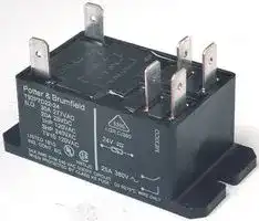

T92P11D22-12
RELAY, DPDT, 277VAC, 28VDC, 40A
- Manufacturer: TE CONNECTIVITY
- Product type: Power Relays
- Contact Configuration:DPDT; Coil Voltage:12VDC; Contact Current:30A; Product Range:T92 Series; Relay Mounting:Panel Mount; Coil Type:Non Latching; Contact Voltage VAC: 17M3081
- SVHC: Cadmium oxide
- Coil Type: Non Latching
- Coil Voltage: 12VDC
- Product Range: T92 Series
- Relay Mounting: Panel Mount
- Coil Resistance: 86ohm
- Contact Current: 30A
- Relay Terminals: Quick Connect
- Contact Material: Silver Cadmium Oxide
- Contact Voltage VAC: 277V
- Contact Voltage VDC: -
- Contact Configuration: DPDT
| Delivery and price | |
|---|---|
| Units per pack | 250 |
| Price | 21.87 € |
| Current stock | 200+ |
| Lead time | 30 days |
General Purpose High Power PCB Relays

**Potter & Brumfield**

## **T92 Series Two-pole 30A PCB or Panel Mount Relay**

## n **40A, 2 form A (NO) and 2 form C (CO) switching capability**

- n **Designed to control compressor loads to 3.5 tons, 110LRA / 25.3FLA**

- n **Meets requirements of UL 508 and UL 873 spacings - 8mm through air, 9.5mm over surface**

- n **Meets requirements of VDE 8mm spacing, 4kV dielectric coil-tocontact**

- n **Meets requirements of UL Class F construction**

- n **UL approved for 600VAC switching (1.5HP)**

- n **New screw terminal version (consult factory for availability, ratings)**

Typical applications

HVAC, residential / commercial appliances,  industrial controls.

|~~**Approvals**~~|||
|---|---|---|
|UL E58304 (Recognized and Listed); CSA LR48471; VDE 40019600|||
|Technical data of approved types on request.|Technical data of approved types on request.||
|~~**Contact Data**~~|||
|Contact arrangement|2 form A (NO), 2 form C (CO)|2 form A (NO), 2 form C (CO)|
|Rated voltage||277VAC|
|Max. switching voltage||600VAC|
|Rated current||30A NO; 3A NC|
|Limiting continuous current||40A NO; 3A NC|
|Limiting making current||40A NO; 3A NC|
|Limiting breaking current||40A NO; 3A NC|
|Contact material||AgSnOInO, AgCdO|
|Min. recommended contact load|500ma (NO)/ 100ma (NC), 12VAC|500ma (NO)/ 100ma (NC), 12VAC|
|Frequency of operation, with load||360hr|
|Operate/release time max., including bounce||Operate/release time max., including bounce<br>25/25ms|


**Contact ratings**[1)] (continued) ARI 780-86 Endurance Test (section 6.6): HVAC Definite Purpose Contactor Standard Normally Open Contacts Single Phase/Two Pole (Both poles together switching a single load) 110 LRA, 25.3 FLA, 200K operations (DC Coil) L1 L2 Figure 1 T1 T2 Single Phase Per Pole (Single load per pole) 110 LRA, 18 FLA, 200K operations (DC Coil). 60 LRA, 14 FLA, 200K operations (AC Coil). L1 L2 Figure 2 T1 T2

|**Contact ratings**1)|**Contact ratings**1)||||||T1|T1||T2||||||
|---|---|---|---|---|---|---|---|---|---|---|---|---|---|---|---|
|Type|Load|Cycles||||||||||||||
|**UL508**||||||||||||||||
|AgCdO|||1) Contact ratings at 25°C (unless otherwise noted) with relay properly vented.||1) Contact ratings at 25°C (unless otherwise noted) with relay properly vented.|1) Contact ratings at 25°C (unless otherwise noted) with relay properly vented.|||||||||1) Contact ratings at 25°C (unless otherwise noted) with relay properly vented.|
|NO|40A, 277VAC, resistive|6x10³|FLA, LRA ratings are compatible with 3.5 ton compressor applications.|FLA, LRA ratings are compatible with 3.5 ton compressor applications.|||||||FLA, LRA ratings are compatible with 3.5 ton compressor applications.|||||
|NO|30A, 120/277VAC, resistive|100x103||||||||||||||
|NO|10A, 600VAC, general purpose|100x103|Mechanical endurance|||||||||||10x10|10x10|
|NO|1HP, 120VAC|100x103||||||||||||||
|NO|3HP, 240VAC|1x10³||||||||||||||
|NO|1.5HP, 480 or 600VAC|100x103|~~**Coil Data**~~|||||||||||||
|NO|110LRA/25.3FLA, 240VAC (DC coil only)|100x103|Coil voltage range|||Coil voltage range|||||5 to 110VDC; 12 to 240VAC|5 to 110VDC; 12 to 240VAC||||
|NO|60LRA/14FLA, 240VAC (AC coil only)|100x103|Max. coil power||Max. coil power||||||||1.7W; 4.0VA|||
|NO|3A, 240VAC, pilot duty|100x103|Max. coil temperature||||||||||155°C|||
|NO|20A, 28VDC, resistive|100x103|Coil insulation system according UL||||||||||Class F|||
|NO|TV10, 120VAC|100x103|**Coil versions, DC coil**|||||**Coil versions, DC coil**||||||||
|NC|3A, 277VAC|100x103|Coil|Rated||||Operate|||Operate|Release||Coil|Rated coil|
|NC|2A, 480VAC|100x103|code|voltage||||voltage<br>voltage|||voltage|voltage|resistance||power|
|NC|1A, 600VAC|100x103||VDC|||VDC|VDC||||VDC||Ω±10%||
|AgSnOInO|||6|6|||||4.5|||0.6||22|1.7|
|NO|30A, 120/277VAC, resistive (DC coil only)|200x103|9|9|||||6.75|||0.9||48|1.7|
|NO|30A, 120/277VAC, resistive (AC coil only)|100x103|12|12|||||9|||1.2||86|1.7|
|NO|20A, 480VAC, resistive|100x103|18|18||||13.5||||1.8||197|1.7|
|NO|1.5HP, 120VAC, 2 pole making/breaking (Fig.1)|100x103|24|24||||18||||2.4||350|1.7|
|NO|3HP, 240VAC, 3 phase (DC coil only)|100x103|48|48||||36||||4.8||1390|1.7|
|NO|3HP, 480VAC, 3 phase (DC coil only)|100x103|110|110||110||82.5||||11||7255|1.7|
|NO|2HP, 600VAC, 3 phase (DC coil only)|100x103|**Coil versions, AC coil**|||||||||||||
|**VDE**|||Coil|Rated||Frequency Operate||||Frequency Operate||Frequency Operate<br>Release||Release<br>Coil|Rated coil|
|AgCdO, flange mount relays|||code voltage|code voltage|code voltage|||||voltage||voltage resistance||voltage resistance|power|
|NO|20A, 400VAC|100x103||VAC||||Hz|VAC, 60Hz VAC, 60Hz Ω±10%||||VAC, 60Hz VAC, 60Hz Ω±10%|||
|NC|3A, 400VAC|30x103|12|12||||60|||9.6|9.6<br>1.2||9.1||
|CO|20A NO / 3A NC, 400VAC|30x103|24|24||||60|||19.2|19.2<br>2.4||36.6||
|AgCdO, PC mount relays|||120|110/120||||50/60|||96|12|12|950||
|NO|30A, 400VAC|100x103|240|220/240||||50/60||192||24|24|3800||
|NC|3A, 400VAC|30x103|277|250/277||||50/60||222||28|28|5485||
|CO|30A NO / 3A NC, 400VAC|30x103|All figures are given for coil without preenergization, at ambient temperature +23°C.||||All figures are given for coil without preenergization, at ambient temperature +23°C.|||||||All figures are given for coil without preenergization, at ambient temperature +23°C.||


|Mechanical endurance|Mechanical endurance|Mechanical endurance|||10x106ops.|10x106ops.|
|---|---|---|---|---|---|---|
||||||||
|~~**Coil Data**~~|||||||
|Coil voltage range||5 to 110VDC; 12 to 240VAC|5 to 110VDC; 12 to 240VAC||||
|Max. coil power||||1.7W; 4.0VA|||
|Max. coil temperature||||155°C|||
|Coil insulation system according UL||||Class F|||
|**Coil versions, DC coil**||**Coil versions, DC coil**|||||
|Coil|Rated|Operate|Release||Coil|Rated coil|
|code|voltage|voltage<br>voltage|voltage|resistance||power|
||VDC|VDC|VDC||Ω±10%|W|
|6|6|4.5|0.6||22|1.7|
|9|9|6.75|0.9||48|1.7|
|12|12|9|1.2||86|1.7|
|18|18|13.5|1.8||197|1.7|
|24|24|18|2.4||350|1.7|
|48|48|36|4.8||1390|1.7|
|110|110|82.5|11||7255|1.7|
|**Coil versions, AC coil**|||||||
|Coil|Rated<br>Frequency Operate||Frequency Operate<br>Release||Release<br>Coil|Rated coil|
|code voltage|code voltage|voltage|voltage resistance||voltage resistance|power|
||VAC|Hz<br>VAC, 60Hz VAC, 60Hz Ω±10%||VAC, 60Hz VAC, 60Hz Ω±10%||VA|
|12|12|60<br>9.6|9.6<br>1.2||9.1|4|
|24|24|60<br>19.2|19.2<br>2.4||36.6|4|
|120|110/120|50/60<br>96|12|12|950|4|
|240|220/240|50/60<br>192|24|24|3800|4|
|277|250/277|50/60<br>222|28|28|5485|4|


11-2012, Rev. 1112 Catalog and product specification according www.te.com to IEC 61810-1 and to be used only together © 2012 Tyco Electronics Corporation, with the ‘Definitions’ section. a TE Connectivity Ltd. company.

Catalog product data, ‘Definitions’ section, application notes and all specifications are subject to change.

1

Catalog and product data is subject to the terms of the disclaimer and all chapters of the ‘Definitions’ section, available at http://relays.te.com/definitions

General Purpose High Power PCB Relays

**Potter & Brumfield**

## **T92 Series Two-pole 30A PCB or Panel Mount Relay** (Continued)

**==> picture [521 x 307] intentionally omitted <==**

**----- Start of picture text -----**<br>
|||||||||||||||||||
|---|---|---|---|---|---|---|---|---|---|---|---|---|---|---|---|---|---|
|Coil Data|(continued)|Other Data|
|Ambient temperature vs. coil voltage|Material compliance: EU RoHS/ELV, China RoHS, REACH, Halogen content|
|Assumptions:|refer to the Product Compliance Support Center at|
|1. Thermal resistance = 35°C per Watt (DC only.)|www.te.com/customersupport/rohssupportcenter|
|2. Still air.|Ambient temperature|
|3. Nominal coil resistance.|DC coil|-55ºC to 85ºC|
|4. Max. mean coil temperature = 155°C (change of resistance method).|AC coil|-55ºC to 65ºC|
|5. Coil temperature rise due to load = 6.3°C @ 30 amps.|Category of environmental protection|
|6. Curves are based on 1.7W at 25°C (DC only.).|IEC 61810|RTI - dust protected,|
|RTII - fux proof, RTIII - wash tight|
|120|Po]|||ft|tf|ft|tT|ft|tf|ft|ft|ft|ft|ft|ft|tf|Vibration resistance (functional)|1.65mm max excursions, 10-55 Hz|
|100|Shock resistance (functional)|10g for 11msec|
|||SSS|
|Shock resistance (destructive)|100g|
|80|,||}eeeSee|Terminal type Weight|PCB-tht  or quick connect 86g|
|60|ee|Ne|ee|ee|ee|OO|
|40|Ne|ee|a|Resistance to soldering heat  THTIEC 60068-2-20|250°C|
|aee|Packaging/unit|tray/30 pcs., box/120 pcs.|
|20|ee|ee|ee|eeeeeeee|OO|
|eeee|eee|
|0|ee|
|70|75|80|85|90|95|100|105|110|115|120|125|130|135|140|145|150|
|Applied Coil Voltage (% of Rated Nominal)|
|Insulation Data|
|Initial dielectric strength|
|between open contacts|1500Vrms|
|between contact and coil|4000Vrms|
|between adjacent contact|2000Vrms|
|Initial surge withstand voltage|
|between contact and coil|6kV|
|Initial insulation resistance|
|between insulated elements|1x10|[9]|Ω|
|Clearance/creepage|
|between contact and coil|8mm clearance/9.5mm creepage|

**----- End of picture text -----**<br>


## **Dimensions**

T92 – Mounting and termination code 1

T92 – Mounting and termination code 2, 3 and 4

**==> picture [517 x 194] intentionally omitted <==**

**----- Start of picture text -----**<br>
2.06 MAX. 1.36 MAX. 2.700 MAX. 1.36 MAX.<br>(52.32) (34.54) (68.58) (34.54)<br>PS oe ——j -<br>1.21 MAX. 1.04 MAX. 1.495 MAX.<br>(30.73) .156 (26.42) (37.97)<br>(3.96)<br>.250 TYP.<br>‘aaT 1.618 ± .020 ae  TaAe (6.35) ooPi r |  _Ll<br>.585 ± .005 (41.10 ± .51) .047 TYP. 2.05 MAX.<br>(14.86 ± .13) .309 ± .005 .032 TYP. (1.19) (52.07)<br>(7.85 ± .13) (0.81) 2.345 ± .005<br>(59.56 ± .13)<br>1.618 TYP.<br>.585 ± .005 (41.10 ± .51)<br>1.000 ± .010 (14.86 ± .13) .309 ± .005<br>.630 ± .005 (25.40 ± .25) (7.85 ± .13)<br>(16.00 ± .13) .090 RAD.<br>(2.29)<br>FOR #8 SCREW<br>na | HH<br>.630 TYP. : a<br>(16.00)<br>**----- End of picture text -----**<br>


2 11-2012, Rev. 1112 www.te.com © 2012 Tyco Electronics Corporation, a TE Connectivity Ltd. company.

Catalog and product specification according to IEC 61810-1 and to be used only together with the ‘Definitions’ section.

Catalog product data, ‘Definitions’ section, application notes and all specifications are subject to change.

Catalog and product data is subject to the terms of the disclaimer and all chapters of the ‘Definitions’ section, available at http://relays.te.com/definitions

General Purpose High Power PCB Relays

**Potter & Brumfield**

## **T92 Series Two-pole 30A PCB or Panel Mount Relay** (Continued)

## **Dimensions**

**==> picture [132 x 8] intentionally omitted <==**

**----- Start of picture text -----**<br>
T92 – Mounting and termination code 5<br>**----- End of picture text -----**<br>


**==> picture [253 x 223] intentionally omitted <==**

**----- Start of picture text -----**<br>
2.700 MAX.<br>(68.58)<br>1.36 MAX.<br>(34.54)<br>.090 (2.29)<br>RAD. FOR<br>#8 SCREW<br>2.345 ± .005<br>(59.56 ± .13)<br>2.135 MAX. 1.431 MAX.<br>— (54.23) — re (36.34)<br>2.010 MAX.<br>(51.05)<br>.913 MAX.<br>(23.19)<br>Po a<br>**----- End of picture text -----**<br>


**==> picture [253 x 386] intentionally omitted <==**

**----- Start of picture text -----**<br>
Terminal assignment<br>Bottom view on pins<br>2 form A  2 form C<br>0 0<br>2 4 2 4 3<br>6 8 6 8 7<br>1 1<br>PCB layout<br>Bottom view on pins<br>T92 - Mounting and termination code 1<br>1.618<br>(41.10)<br>.585<br>.309 (14.86) .185<br>(7.85) (4.70)<br>.365<br>(9.27)<br>.630 1.000<br>(16.00) (25.40)<br>.203 TYP.<br>(5.16) .052 TYP. .072 TYP.<br>(1.32)<br>.162 (1.83)<br>(4.12)<br>An alternate PC board layout utilizes .076 ± .003 (1.93 ± .076) diameter holes on the same<br>center-to-center spacing shown above. Use of the rectangular holes is recommended for<br>improved solderability.<br>**----- End of picture text -----**<br>


Only necessary terminals are present on single throw models. Consequently, some holes will be unnecessary for single throw models.

|**Product code structure**<br>Typical product code|**Product code structure**<br>Typical product code|**T92**|**S**|**11**|**D**||**2**|**2**|**-24**|
|---|---|---|---|---|---|---|---|---|---|
|**Type**||||||||||
|**T92**|Printed circuit board / panel mount power relay T92|||||||||
|**Enclosure**||||||||||
|**P**|Dust protected plastic case|||||||||
|**S**|Wash-tight, tape sealed, plastic case (Mounting and termination code 1)|||||||||
||Top sealed, not wash-tight, not tape sealed on bottom (Mounting and termination codes 2, 3 & 4)|||||||||
|**Contact arrangement**||||||||||
|**7**|2 form A (2 NO)<br>**11**2 form C (2 CO)|||||||||
|**Coil Input**||||||||||
|**A**|AC voltage, 60Hz or 50/60 Hz (consult coil versions table)<br>**D**DC voltage|||||||||
|**Mounting and termination**|**Mounting and termination**|||||||||
|**1**|Printed circuit board mount; printed circuit board terminals.|||||||||
|**2**<br>**3**<br>**4**<br>**5**|Panel mount via flanged cover; .250” (6.35mm) x .032” (.81mm) QC terminal<br>Panel mount via flanged cover; .187” (4.75mm) x .032” (.81mm) QC terminals for coil and .250” (6.35mm) for contacts<br>Panel mount via flanged cover, .187” (4.75mm) x .020” (.51mm) QC terminals for coil and .250” (6.35mm) for contacts.<br>Panel mount via flanged cover, M4 screws w/ captive pressure plates. Requires Enclosure P and Contact arrangement 7.||||||Panel mount via flanged cover, M4 screws w/ captive pressure plates. Requires Enclosure P and Contact arrangement 7.|||
|**Contact material**||||||||||
|**2**|AgCdO<br>**4**<br>AgSnOInO|||||||||
|**Coil voltage**||||||||||
||Coil code: please refer to coil versions table|||||||||


Catalog and product specification according to IEC 61810-1 and to be used only together with the ‘Definitions’ section.

Catalog and product data is subject to the Catalog product data, ‘Definitions’ section, terms of the disclaimer and all chapters of application notes and all specifications are the ‘Definitions’ section, available at subject to change. http://relays.te.com/definitions

3

11-2012, Rev. 1112 www.te.com © 2012 Tyco Electronics Corporation, a TE Connectivity Ltd. company.

General Purpose High Power PCB Relays

**Potter & Brumfield**

## **T92 Series Two-pole 30A PCB or Panel Mount Relay** (Continued)

|T92P7A22-24<br>T92P7A22-120<br>T92P7A22-240<br>T92P7A22-277<br>T92P7A24-240<br>T92P7A52-120<br>T92P7A52-240<br>T92P7D12-12<br>T92P7D12-24<br>T92P7D22-12<br>T92P7D22-24<br>T92P7D22-48<br>T92P7D24-12<br>T92P7D24-24<br>T92P7D42-24<br>T92P7D52-12<br>T92P7D52-24<br>T92P11A12-120<br>T92P11A22-12<br>T92P11A22-24<br>T92P11A22-120<br>T92P11A22-240<br>T92P11A22-277<br>T92P11A24-240<br>T92P11A42-120<br>T92P11D12-12<br>T92P11D22-12<br>T92P11D22-24<br>T92P11D24-12<br>T92P11D24-24<br>T92S7A12-24<br>T92S7A12-120<br>T92S7A12-240<br>T92S7A22-24<br>T92S7A22-120<br>T92S7A22-240<br>T92S7D12-12<br>T92S7D12-24<br>T92S7D12-48<br>T92S7D12-110<br>T92S7D14-24<br>T92S7D22-12<br>T92S7D22-18<br>T92S7D22-24<br>T92S7D22-110<br>T92S11A12-24<br>T92S11A12-120<br>T92S11A12-240<br>T92S11A22-12<br>T92S11A22-24<br>T92S11A22-120<br>T92S11A22-240<br>T92S11D12-12<br>T92S11D12-24<br>T92S11D12-48<br>T92S11D12-110<br>T92S11D22-12<br>T92S11D22-24|Plastic dust cover|2 form A, 2 NO|AC<br>~~a_—e—~~<br>~~a~~|Panel mount + quick connect<br>~~ee~~<br>~~a_—e—~~|AgCdO<br>~~||~~|24 VAC<br>~~|~~|6-1393211-0<br>5-1393211-7<br>6-1393211-2<br>6-1393211-3<br>3-1423008-3<br>1423008-8<br>1-1423008-2<br>6-1393211-5<br>6-1393211-6<br>6-1393211-9<br>7-1393211-1<br>7-1393211-2<br>2-1423008-2<br>1423008-9<br>7-1393211-5<br>1-1423008-0<br>1423967-1<br>3-1393211-8<br>3-1393211-9<br>4-1393211-3<br>4-1393211-0<br>4-1393211-4<br>4-1393211-6<br>3-1423008-7<br>4-1393211-8<br>5-1393211-0<br>5-1393211-3<br>5-1393211-4<br>3-1423008-5<br>3-1423008-6<br>9-1393211-8<br>9-1393211-7<br>9-1393211-9<br>1393212-4<br>1393212-2<br>1393212-5<br>1393212-8<br>1-1393212-0<br>1-1393212-1<br>1393212-7<br>1-1423008-8<br>1-1393212-4<br>1-1393212-5<br>1-1393212-7<br>1-1393212-3<br>8-1393211-1<br>8-1393211-0<br>8-1393211-2<br>8-1393211-3<br>8-1393211-6<br>8-1393211-4<br>8-1393211-7<br>8-1393211-9<br>9-1393211-0<br>9-1393211-1<br>8-1393211-8<br>9-1393211-3<br>9-1393211-4<br>~~|~~|
|---|---|---|---|---|---|---|---|
|||||||120VAC<br>~~|~~<br>~~[|~~<br>~~|~~||
|||||||240VAC<br>~~[|~~<br>~~||~~||
|||||||277 VAC<br>~~||~~||
||||||AgSnOInO<br>~~|~~<br>~~ee~~|240VAC<br>~~|~~<br>~~ee~~||
|||||Panel mount + screw terminals<br>~~ee~~<br>~~a_—e—~~<br>~~a~~|AgCdO<br>~~ee~~<br>~~|~~<br>~~||~~|120VAC<br>~~ee~~<br>~~—~~||
|||||||240VAC<br>~~ee~~<br>~~—~~<br>~~|~~<br>~~—~~||
||||DC<br>~~a_—e—~~<br>~~a~~<br>~~—_—e—o_—e~~|PCB terminals<br>~~ee~~<br>~~a_—e—~~<br>~~a~~||12 VDC<br>~~ee~~<br>~~|~~<br>~~—~~<br>~~|~~||
|||||||24 VDC<br>~~—~~<br>~~|~~||
|||||Panel mount + quick connect<br>~~a~~<br>~~oe~~<br>~~—_—e—o_—e~~||12VDC<br>~~—~~<br>~~||~~<br>~~|~~||
|||||||24 VDC<br>~~—~~<br>~~|~~<br>~~||~~||
|||||||48VDC<br>~~|||~~||
||||||AgSnOInO<br>~~|~~<br>~~oe~~|12VDC<br>~~||~~<br>~~oe~~||
|||||||24 VDC<br>~~oe~~||
||||||AgCdO<br>~~oe~~<br>~~|~~<br>~~|~~<br>~~|~~|||
|||||Panel mount + screw terminals<br>~~oe~~<br>~~—_—e—o_—e~~<br>~~_~~||12 VDC<br>~~oe~~<br>~~—~~<br>~~|~~||
|||||||24 VDC<br>~~oe~~<br>~~|~~<br>~~|~~||
|||2 form C, 2 CO|AC<br>~~—_—e—o_—e~~|PCB terminals<br>~~oe~~<br>~~—_—e—o_—e~~<br>~~_~~||120 VAC<br>~~oe~~<br>~~|~~<br>~~|~~||
|||||Panel mount + quick connect<br>~~_~~<br>~~ee~~<br>~~a~~||12 VAC<br>~~|~~<br>~~||~~||
|||||||24 VAC<br>~~|~~<br>~~|~~||
|||||||120 VAC<br>~~|~~<br>~~|~~||
|||||||240 VAC<br>~~|~~<br>~~|~~<br>~~|~~||
|||||||277 VAC<br>~~|~~<br>~~|~~||
||||||AgSnOInO<br>~~|~~<br>~~ee~~|240 VAC<br>~~|~~<br>~~ee~~||
||||||AgCdO<br>~~ee~~<br>~~a~~<br>~~|~~|120VAC<br>~~ee~~<br>~~a~~||
||||DC|PCB terminals<br>~~a~~||12 VDC<br>~~a~~<br>~~|~~||
|||||Panel mount + quick connect<br>~~a~~<br>~~Po~~||||
|||||||24 VDC<br>~~a~~<br>~~|~~||
||||||AgSnOInO<br>~~|~~<br>~~Po~~|12 VDC<br>~~|~~<br>~~Po~~||
|||||||24 VDC<br>~~Po~~<br>~~[|~~||
||Wash tight|2 form A, 2 NO|AC|PCB terminals|AgCdO<br>~~|~~<br>~~|~~<br>~~||~~|24 VAC<br>~~|~~||
|||||||120 VAC<br>~~|~~<br>~~|~~||
|||||||240 VAC<br>~~|~~<br>~~|~~<br>~~|~~||
||Top sealed|||Panel mount + quick connect||24 VAC<br>~~|~~<br>~~|~~||
|||||||120 VAC<br>~~||~~||
|||||||240 VAC<br>~~|~~<br>~~|~~||
||Wash tight||DC|PCB terminals<br>~~ee~~||12 VDC<br>~~|~~<br>~~|~~||
|||||||24 VDC<br>~~||~~<br>~~|~~||
|||||||48 VDC<br>~~|~~<br>~~||~~||
|||||||110 VDC<br>~~||~~||
||||||AgSnOInO<br>~~|~~<br>~~ee~~|24 VDC<br>~~|~~<br>~~ee~~||
||Top sealed|||Panel mount + quick connect<br>~~ee~~|AgCdO<br>~~ee~~<br>~~|~~<br>~~|~~<br>~~|~~<br>~~|~~<br>~~|~~|12 VDC<br>~~ee~~<br>~~[|~~||
|||||||18 VDC<br>~~|~~||
|||||||24 VDC<br>~~|~~<br>~~|~~||
|||||||110 VDC<br>~~|~~<br>~~|~~||
||Wash tight|2 form C, 2 CO|AC|PCB terminals||24 VAC<br>~~|~~<br>~~|~~||
|||||||120 VAC<br>~~|~~<br>~~|~~||
|||||||240 VAC<br>~~|~~<br>~~|~~||
||Top sealed|||Panel mount + quick connect||12 VAC<br>~~|~~<br>~~|~~||
|||||||24 VAC<br>~~||~~<br>~~|~~||
|||||||120 VAC<br>~~|~~<br>~~|~~||
|||||||240 VAC<br>~~||~~<br>~~|~~||
||Wash tight<br>~~a~~||DC<br>~~Po~~|PCB terminals<br>~~Po~~||12 VDC<br>~~|~~||
|||||||24 VDC<br>~~|[|~~<br>~~|~~||
|||||||48 VDC<br>~~|~~||
|||||||110 VDC<br>~~|[|~~<br>~~—~~||
||Top sealed<br>~~a~~|||Panel mount + quick connect<br>~~Po~~||12 VDC<br>~~—|~~||
|||||||24 VDC<br>~~—|~~||


4

Catalog and product specification according to IEC 61810-1 and to be used only together with the ‘Definitions’ section.

Catalog product data, ‘Definitions’ section, application notes and all specifications are subject to change.

Catalog and product data is subject to the terms of the disclaimer and all chapters of the ‘Definitions’ section, available at http://relays.te.com/definitions

11-2012, Rev. 1112 www.te.com © 2012 Tyco Electronics Corporation, a TE Connectivity Ltd. company.
Updated at June 4, 2026
TE Connectivity is a globally recognized engineering and manufacturing leader, specializing in highly reliable connectivity and sensing solutions. Renowned for innovation and durability, their components are engineered to perform in the most demanding environments, supporting critical advancements in industrial equipment, data communications, and automotive systems. Our extensive selection of TE Connectivity products is anchored by their industry-leading connector portfolio. We carry a comprehensive array of terminal blocks and accessories, including wire-to-board, pluggable, standard, and barrier configurations, alongside robust backplane connectors designed to ensure secure and efficient power and data transmission in complex circuit designs. Beyond physical connections, TE Connectivity is a premier manufacturer of precision sensors, antennas, and electromechanical switching components. Our inventory features a wide variety of RF antennas and highly accurate pressure, temperature, and force transducers. Additionally, we provide an expansive range of TE's dependable relays, encompassing automotive, power, and signal variants, alongside essential passive components like shielding gaskets and RF inductors to fully support your engineering requirements.
About Novapart
Novapart is a B2B electronic component broker specialising in stock shortages and cost reduction. We source hard-to-find parts and identify compliant alternatives across a catalogue of 410,000+ components from 500+ manufacturers.
Learn more →Stock Shortage Specialist
When a component is unavailable, discontinued or has an unacceptable lead time, we tap into our network of vetted European and Asian distributors to source what you need — without compromising on quality or traceability.
Request a quote →Compliant Alternatives
We identify pin-to-pin, electrically equivalent substitutes that meet the same certifications (RoHS, AEC-Q100, REACH) as your original specification — validated against datasheets, not just part numbers. Often at a lower cost.
BOM Analysis service →