
Image not available
Illustrative purposes only

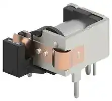
T90N1D42-12
Power Relay, SPST-NO, 12 VDC, 30 A, T90 Series, Through Hole
⚠️ Reference pricing provided. In case of supply shortages, we will connect you with our trusted procurement partners to ensure your project's continuity.
- Manufacturer: TE CONNECTIVITY - POTTER&BRUMFIELD
- Product type: Power Relays
- Contact Configuration:SPST-NO; Coil Voltage:12VDC; Contact Current:30A; Product Range:T90 Series; Relay Mounting:Through Hole; Coil Type:-; Contact Voltage VAC:277V; Relay Terminals
- SVHC: To Be Advised
- Coil Type: -
- Coil Voltage: 12VDC
- Product Range: T90 Series
- Relay Mounting: Through Hole
- Coil Resistance: 155ohm
- Contact Current: 30A
- Relay Terminals: Solder
- Contact Material: Silver Cadmium Oxide
- Contact Voltage VAC: 277V
- Contact Voltage VDC: -
- Approvals & Standards: CSA, UL
- Contact Configuration: SPST-NO
| Delivery and price | |
|---|---|
| Units per pack | 50 |
| Price | 3.97 € |
| Current stock | 10+ |
| Lead time | 7 days |
Datasheet

General Purpose High Power PCB Relays

**Potter & Brumfield**

## **T90 Series, 30A PCB Relay**

## n **30A, 1 form A (NO); 20A, 1 form C (CO)**

> n **Available as open frame or sealed construction**

> n **Meets UL 508 and 873 Spacing - 3.18 through air, 6.36 over surface**

> n **UL class F insulation system standard**

Typical applications HVAC,  Appliances, Industrial Controls.

|~~**Approvals**~~||||
|---|---|---|---|
|UL E22575; CSA LR15734||||
|Technical data of approved types on request.|Technical data of approved types on request.|Technical data of approved types on request.||
|~~**Contact Data**~~||||
|Contact arrangement|1 form A (NO), 1 form B (NC), 1 form C (CO)|||
|Rated voltage|||277VAC|
|Max. switching voltage|||277VAC|
|Rated current|||30A|
|Limiting continuous current|Limiting continuous current||30A|
|Limiting making current|||30A|
|Limiting breaking current|||30A|
|Contact material|||AgCdO|
|Min. recommended contact load|Min. recommended contact load|1A, 5VDC or 12VAC||
|Initial contact resistance||75 mΩ at 1A at 5VDC or 12VAC||
|Frequency of operation, with load|||360hr|
|Operate/release time max., including bounce|||15/15ms|


## **Contact ratings**

|Type<br>**Typical**<br>AgCdO, open style relay<br>NO<br>NO<br>CO<br>CO<br>**UL 508/873**<br>AgCdO<br>NO<br>NC<br>CO<br>NO|Load<br>AgCdO, open style relay<br>30A, 240VAC, general purpose<br>20A, 240VAC, resistive heater<br>20A/10A, 240VAC, general purpose<br>20A/10A, 28VDC, resistive<br>30A, 240VAC, general purpose<br>15A, 240VAC, general purpose<br>20A/10A, 240VAC, general purpose<br>20A, 240VAC, resistive|Cycles<br>100x103<br>100x103<br>100x103<br>100x103<br>100x103<br>100x103<br>100x103<br>100x103|
|---|---|---|
|NC|15A, 240VAC, resistive|100x103|
|CO<br>NO<br>NC<br>CO<br>NO<br>NO<br>NC<br>NO<br>NC<br>NO<br>NC<br>NO<br>NC<br>NO<br>NC|20A/10A, 240VAC, resistive<br>80LRA/30FLA, 240VAC<br>30LRA/10FLA, 240VAC<br>53.6LRA/20FLA / 20LRA/6.7FLA, 240VAC<br>98LRA/22FLA, 120VAC<br>2HP, 240VAC<br>1/2HP, 240VAC<br>1HP, 120VAC<br>1/4HP, 120VAC<br>6A, 277VAC, ballast<br>3A, 277VAC, ballast<br>TV5, 240VAC, tungsten<br>TV3, 240VAC, tungsten<br>20A, 28VDC, resistive<br>10A, 28VDC, resistive|100x103<br>30x103<br>30x103<br>100x103<br>100x103<br>1x10³<br>1x10³<br>1x10³<br>1x10³<br>100x103<br>6x10³<br>6x10³<br>6x10³<br>100x103<br>100x103|


All ratings at 25°C (unless otherwise noted) with relay properly vented. Remove vent nib from enclosed relays after soldering and cleaning for optimum life.

10x10[6] ops.

Mechanical endurance

|~~**Coil Data**~~|~~**Coil Data**~~|||||
|---|---|---|---|---|---|
|Coil voltage range|Coil voltage range|||5 to 110VDC||
|Max. coil power||||1.0W||
|Max. coil temperature||||155°C||
|Coil insulation system according UL|||Coil insulation system according UL|Class F||
|**Coil versions, DC coil**||**Coil versions, DC coil**||||
|Coil|Rated|Operate|Release|Release<br>Coil|Rated coil|
|code|voltage|voltage|voltage|resistance|power|
||VDC|VDC|VDC|Ω±10%|wW|
|5|5|3.75|0.5|27|900|
|6|6|4.5|0.6|40|900|
|9|9|6.75|0.9|97|900|
|12|12|9|1.2|155|900|
|18|18|13.5|1.8|380|900|
|24|24|18|2.4|660|900|
|48|48|36|4.8|2560|900|
|110|110|82.5|11|13450|900|


All figures are given for coil without preenergization, at ambient temperature +23°C.

## **Ambient temperature vs. coil voltage – 1W coil**

**==> picture [203 x 230] intentionally omitted <==**

**----- Start of picture text -----**<br>
130<br>120 Open Style Relay, No Dust Cover<br>110 Se<br>100 a ee ee [Le<br>90 eee<br>80<br>70<br>60 30A Load aE Zee<br>50 25A Load<br>40 20A Load Lier eT<br>15A Load<br>30 10A Load = ae ee ee eee<br>0A Load<br>ce<br>2050 75 100 125 150 175 200 225<br>Applied Continuous Coil Voltage (% of Rated Voltage)<br>150<br>140 Wash Tight Relay, Vented<br>130 e e e<br>120 ee Pe<br>110<br>10090 CAE= &@M@ IJA®<br>80<br>70 30A Load<br>60 e 25A Load S22A EEE|<br>50<br>20A Load<br>40 15A Load<br>30 10A Load<br>p 0A Load a eeeee<br>2050 75 100 125 150 175 200 225<br>Applied Continuous Coil Voltage (% of Rated Voltage)<br>Coil Temp. Rise Above Ambient (°C)<br>Coil Temp. Rise Above Ambient (°C)<br>**----- End of picture text -----**<br>


Data graphed above are average values and should be verified in application. Tests were conducted within a 2’ (.6m) cube (still air); at nominal coil power @ 25°C; with normally open contact loaded; and with 4’ (1.22m) long, #10AWG load wires. P.C. board relays were mounted to a 30A, single side P.C. board. Coil rise test conducted with a 30A PC board to maintain 20°C max. rise at 30°C. The relay connections and wiring must be designed with an adequate cross section to ensure proper current flow and heat dissipation. After cleaning process knock-off nib should be removed for optimum life of wash-tight relays.

1

02-2014, Rev. 0214 Catalog and product specification according www.te.com to IEC 61810-1 and to be used only together © 2014 Tyco Electronics Corporation, with the ‘Definitions’ section. a TE Connectivity Ltd. company.

Catalog product data, ‘Definitions’ section, application notes and all specifications are subject to change.

Catalog and product data is subject to the terms of the disclaimer and all chapters of the ‘Definitions’ section, available at http://relays.te.com/definitions

General Purpose High Power PCB Relays

**Potter & Brumfield**

## **T90 Series, 30A PCB Relay** (Continued)

|~~**Insulation Data**~~||
|---|---|
|Initial dielectric strength||
|between open contacts|1500Vrms|
|between contact and coil|1500V~~rms~~|
|Initial insulation resistance||
|between insulated elements|1x10⁹Ω|
|Clearance/creepage||
|between contact and coil|3.17mm|
|||
|~~**Other Data**~~||
|Material compliance: EU RoHS/ELV, China RoHS, REACH, Halogen content||
|refer to the Product Compliance Support Center at<br>www.te.com/customersupport/rohssupportcenter||
|Ambient temperature||
|DC coil|-55ºC to 85ºC1)|
|Category of environmental protection||
|IEC 61810<br>RT0|RT0-open, RTIII-wash tight|


|~~**Other Data**(continued)~~||
|---|---|
|Vibration resistance (functional)|1.65mm max excursions, 10-55 Hz|
|Shock resistance (functional)|10g for 11msec|
|Shock resistance (destructive)|100g|
|Terminal type|PCB-tht|
|Weight|20g  open relay|
||26g wash-tight relay|
|Resistance to soldering heat  THT||
|IEC 60068-2-20|250°C|
|Packaging/unit|tray/50 pcs., box/500 pcs.|


- 1) Operating ambient temperature must consider “Must Operate Voltage Change Over Temperature,” Contact Temperature Rise, Coil Temperature Rise (If coil is not allowed to cool) and Maximum Coil Temperature. Specification ambient considers 20A load with coil cooled to ambient.

## **Dimensions**

**==> picture [521 x 135] intentionally omitted <==**

**----- Start of picture text -----**<br>
T90N T90S<br>.031 x .062 .130 + .016<br>.680 MAX. (.79 x 1.58) .805 MAX.         – .010 .212 MAX.<br>.950 MAX.(24.13) (17.27) .130  .020(3.3  .51)TERMINALS (20.4) (           –.253.30 + .41 ) (5.38) TERMINALS.032 x .062(.8 x 1.6)<br>.50 .10 MAX.<br>1.20 MAX. .69 (12.8) (2.54)<br>(30.5) (17.6)<br>1.27 MAX.<br>(32.26)<br>.025 x .025<br>TERMINALS.025 x .025(.64 x .64) (1.14 x 1.14)TERMINALS.045 x .045 le 1.08 MAX.(27.43) TT .016(.43) a 2xTERMINALS(.64 x .64) 2x (1.14 x 1.14).045 x .045 y<br>TERMINALS<br>**----- End of picture text -----**<br>


**==> picture [200 x 128] intentionally omitted <==**

**----- Start of picture text -----**<br>
Terminal assignment<br>Bottom view on pins<br>1 form A  1 form B  1 form C<br>colo cl<br>Note: This terminal is not present on relays with terminal code 4.<br>**----- End of picture text -----**<br>


**==> picture [71 x 17] intentionally omitted <==**

**----- Start of picture text -----**<br>
PCB layout<br>Bottom view on pins<br>**----- End of picture text -----**<br>


**==> picture [249 x 124] intentionally omitted <==**

**----- Start of picture text -----**<br>
.081 ± .005 DIA.<br>(2.06 ± .13)<br>.078 ± .003 DIA.<br>.300 .100 (1.98 ± .08) Only necessary terminals are<br>(7.62) (2.54) present on single throw models<br>and terminal code 4 models.<br>Consequently, some holes will be<br>.600 .600 unnecessary for those models.<br>(15.24) (15.24)<br>.043 ± .003 DIA.<br>(1.09 ± .08) tun e<br>.150 .350<br>(3.81) (8.89).550<br>(13.97)<br>.700<br>(17.78)<br>**----- End of picture text -----**<br>


## ~~**Accessory**~~

Optional plastic dust cover is a snap-on unit, open on the PC board side of the relay. The cover, when ordered with the relay, is shipped separately. It is designed to be snapped into place by the customer after the relay has been assembled to the PC board.

|Product Code Description<br>35C620A|Product Code Description<br>Black dust cover, for use on T90N relay|Part Number<br>4-1393209-2|
|---|---|---|


35C620A

**==> picture [169 x 103] intentionally omitted <==**

**----- Start of picture text -----**<br>
.719 1.067 MAX.<br>(18.26) (27.1)<br>ro Ir i<br>.50<br>.69 (12.7)<br>(17.5)<br>1.256 MAX.<br>(31.9)<br>a .090<br>(2.29) .87<br>(22.1)<br>**----- End of picture text -----**<br>


2

Catalog and product specification according to IEC 61810-1 and to be used only together with the ‘Definitions’ section.

Catalog product data, ‘Definitions’ section, application notes and all specifications are subject to change.

Catalog and product data is subject to the terms of the disclaimer and all chapters of the ‘Definitions’ section, available at http://relays.te.com/definitions

02-2014, Rev. 0214 www.te.com © 2014 Tyco Electronics Corporation, a TE Connectivity Ltd. company.

General Purpose High Power PCB Relays

**Potter & Brumfield**

|**T90 Series, 30A PCB Relay**(Continued)|**T90 Series, 30A PCB Relay**(Continued)||||||||
|---|---|---|---|---|---|---|---|---|
|**Product code structure**<br>Typical product code<br>**T90**<br>**S**<br>**5**<br>**Type**<br>**T90**<br>Power PCB relay T90<br>**Enclosure**<br>**N**<br>Open, no enclosure (snap-on dust cover available as an option)<br>**S**<br>Wash-tight, sealed plastic case with knock off nib for ventilation<br>**Contact arrangement**<br>**1**<br>1 form A (1 NO)<br>**2**<br>1 form B (1 NC)<br>**5**<br>1 form C (1 CO)<br>**Coil Input**<br>**D**<br>DC voltage<br>**Mounting and termination**<br>**1**<br>PCB terminals<br>**4**<br>PCB terminals, no common terminal between coil terminals (see PCB layout/terminal assignment drawing)<br>Note: Terminal code 4 recommended for UL 873 applications. Consult factory for use of terminal code 1 for UL 873 applications.<br>**Contact material**<br>**2**<br>AgCdO<br>~~—~~||||**D**<br>**1**<br> J|||**2**|**-24**|
|**Coil voltage**|||||||||
|Coil code: please refer to coil versions table|||||||||


|T90N1D12-5<br>T90N1D12-9<br>T90N1D12-12<br>T90N1D12-18<br>T90N1D12-24<br>T90N1D12-48<br>T90N1D12-110<br>T90N1D42-12<br>T90N1D42-24<br>T90N5D12-5<br>T90N5D12-12<br>T90N5D12-18<br>T90N5D12-24<br>T90N5D12-48<br>T90N5D12-110<br>T90N5D42-12<br>T90N5D42-24<br>T90S1D12-5<br>T90S1D12-6<br>T90S1D12-9<br>T90S1D12-12<br>T90S1D12-18<br>T90S1D12-24<br>T90S1D42-12<br>T90S1D42-24<br>T90S1D42-48<br>T90S5D12-5<br>T90S5D12-12<br>T90S5D12-18<br>T90S5D12-24<br>T90S5D12-48<br>T90S5D42-12<br>T90S5D42-18<br>T90S5D42-24<br>=|open, no cover<br>=~~==~~|1 form A, 1 NO<br>~~==~~|PCB<br>~~==~~|AgCdO<br>~~==~~—~~=~~<br>~~===~~|5VDC<br>~~-~~|7-1393208-4<br>7-1393208-5<br>6-1393208-5<br>6-1393208-8<br>7-1393208-0<br>7-1393208-3<br>6-1393208-4<br>7-1393208-7<br>7-1393208-9<br>9-1393208-5<br>8-1393208-6<br>9-1393208-0<br>9-1393208-3<br>9-1393208-4<br>8-1393208-5<br>9-1393208-9<br>1393209-2<br>1-1393209-8<br>1-1393209-9<br>2-1393209-0<br>1-1393209-2<br>1-1393209-3<br>1-1393209-6<br>2-1393209-2<br>2-1393209-5<br>2-1393209-6<br>3-1393209-4<br>2-1393209-8<br>3-1393209-0<br>3-1393209-1<br>3-1393209-3<br>1423094-1<br>3-1393209-8<br>4-1393209-0|
|---|---|---|---|---|---|---|
||||||9VDC<br>~~-~~||
||||||12 VDC<br>~~-~~||
||||||18VDC<br>~~-~~||
||||||24 VDC<br>~~-~~||
||||||48VDC<br>~~-~~||
||||||110VDC<br>~~-~~||
||||PCB, no extra COM<br>~~==~~||12 VDC<br>~~-~~||
||||||24 VDC<br>~~-~~||
|||1 form C, 1 CO<br>~~==~~<br>~~==~~|PCB<br>~~==~~<br>~~==~~||5VDC<br>~~-~~<br>~~=~~||
||||||12 VDC<br>~~-~~<br>~~=~~||
||||||18VDC<br>~~-~~<br>~~=~~||
||||||24 VDC<br>~~-~~<br>~~=~~||
||||||48 VDC<br>~~-~~<br>~~=~~||
||||||110 VDC<br>~~-~~<br>~~=~~||
||||PCB, no extra COM<br>~~==~~<br>~~==~~||12VDC<br>~~-~~<br>~~=~~||
||||||24 VDC<br>~~-~~<br>~~=~~||
||wash tight|1 form A, 1 NO<br>~~==~~<br>~~==~~|PCB<br>~~==~~<br>~~==~~||5 VDC<br>~~=~~<br>~~—~~||
||||||6 VDC<br>~~=~~<br>~~—~~||
||||||9 VDC<br>~~—~~||
||||||12 VDC<br>~~—~~||
||||||18 VDC<br>~~—~~||
||||||24 VDC<br>~~—~~||
||||PCB, no extra COM<br>~~==~~||12 VDC<br>~~—~~||
||||||24 VDC<br>~~—~~||
||||||48 VDC<br>~~—~~||
|||1 form C, 1 CO<br>~~==~~<br>~~===~~|PCB<br>~~==~~<br>~~===~~||5 VDC<br>~~—~~<br>~~===~~||
||||||12 VDC<br>~~—~~<br>~~===~~||
||||||18 VDC<br>~~===~~||
||||||24 VDC<br>~~===~~||
||||||48 VDC<br>~~===~~||
||||PCB, no extra COM<br>~~===~~<br>~~a~~||12 VDC<br>~~===~~<br>~~—~~||
||||||18 VDC<br>~~===~~<br>~~—~~||
||||||24 VDC<br>~~===~~<br>~~—~~||


3

Catalog product data, ‘Definitions’ section, application notes and all specifications are subject to change.

Catalog and product data is subject to the terms of the disclaimer and all chapters of the ‘Definitions’ section, available at http://relays.te.com/definitions

02-2014, Rev. 0214 www.te.com © 2014 Tyco Electronics Corporation, a TE Connectivity Ltd. company.
Updated at March 17, 2026
About Novapart
Novapart is a B2B electronic component broker specialising in stock shortages and cost reduction. We source hard-to-find parts and identify compliant alternatives across a catalogue of 410,000+ components from 500+ manufacturers.
Learn more →Stock Shortage Specialist
When a component is unavailable, discontinued or has an unacceptable lead time, we tap into our network of vetted European and Asian distributors to source what you need — without compromising on quality or traceability.
Request a quote →Compliant Alternatives
We identify pin-to-pin, electrically equivalent substitutes that meet the same certifications (RoHS, AEC-Q100, REACH) as your original specification — validated against datasheets, not just part numbers. Often at a lower cost.
BOM Analysis service →