
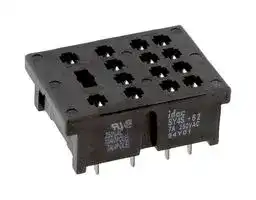


SY4S-62
Relay Socket, Through Hole, Through Hole, 14 Pins, 7 A, 250 V, RU Series
- Manufacturer: IDEC
- Product type: Relay Sockets
- SVHC: No SVHC (25-Jun-2025)
- No. of Pins: 14Pins
- Product Range: RU Series
- Current Rating: 7A
- Voltage Rating: 250V
- Socket Mounting: Through Hole
- Socket Terminals: Through Hole
| Delivery and price | |
|---|---|
| Units per pack | 100 |
| Price | 1.18 € |
| Current stock | 10+ |
| Lead time | 30 days |
**==> picture [482 x 377] intentionally omitted <==**

**----- Start of picture text -----**<br>
|||
|---|---|
|Selection Guide.................................. F-2|
|Din Rail Snap/Surface-Mount|
|Section|Sockets|
|• SU Series . . . . . . . . . . . . . . . . . . . ..F-6|
|• SJ Series . . . . . . . . . . . . . . . . . . . . ..F-9|
|• SQ Series . . . . . . . . . . . . . . . . . . . F-10|
|• SR Series . . . . . . . . . . . . . . . . . . . F-11|
|}|
|• SH Series . . . . . . . . . . . . . . . . . . . F-14|
|• SY Series . . . . . . . . . . . . . . . . . . . F-18|
|• SM Series. . . . . . . . . . . . . . . . . . . F-20|
|Through Panel Mount Sockets|
|• SR Series . . . . . . . . . . . . . . . . . . . F-21|
|i]|• SH Series . . . . . . . . . . . . . . . . . . . F-22|
|• SY Series . . . . . . . . . . . . . . . . . . . F-24|
|PCB Mount Sockets|
|F|
|• SH Series . . . . . . . . . . . . . . . . . . . F-25|
|• SY Series . . . . . . . . . . . . . . . . . . . F-26|
|Panel Mounted Sockets for Timers|
|• SR Series . . . . . . . . . . . . . . . . . . . F-28|
|Accessories....................................... F-29|
|Dimensions....................................... F-31|

**----- End of picture text -----**<br>


**Selection Guide.................................. F-2**

for more information on this product family visit **www.idec.com/socket Additional Web Resources** • New and updated product information ™ • Downloadable software demos & upgrades • Part configuration tool & cross reference • Online stock check & ordering • IDEC field sales & distributor search • Online literature request • Downloadable manuals & CAD drawings • Manufacturer’s suggested retail price list • Product training schedule & locations • Advertising & trade show schedules • Press releases & FAQs ™ ia, a

_**Sockets**_

Selection Guide

**F** ll a. :

## fC

**Relay and Timer Socket**

## **Relay and Timer Socket Selection Guide**

|**Mounting**|**Series**|**Page**|**Part No.**|**No. of**<br>**Poles**|**Receptacle**|**Terminal**|**Compatible**<br>**IDEC Relay and Timer**|
|---|---|---|---|---|---|---|---|
||SU<br>pee|F-6<br>pee|SU2S-11L<br>pee|2<br>pee|8-Blade<br>pee|Spring Clamp<br>Terminals<br>pee|RU2, RM2|
||||SU4S-11L<br>pee<br>Tr|4<br>pee<br>Tr|14-Blade<br>pee<br>Tr||RU4, RU42, RY4, RY42|
||SR<br>pee|F-11<br>pee|SR2P-05<br>SR2P-05C<br>SR2P-06<br>pee|2<br>pee|8-Pin<br>pee|M3.5 Screw<br>pee|RR2P, GT5P,<br>RTE-P1, GT3 (8-pin)|
||||SR3P-05<br>SR3P-05C<br>SR3P-06|3|11-Pin||RR3PA, RR2KP, RTE-P2<br>GT3 (11-pin)|
||||SR3B-05<br>TI<br>ee|3<br>TI|11-Blade<br>TI||RR1BA, RR2BA, RR3B, RTE-B|
||SH|F-14<br>ee|SH1B-05<br>SH1B-05C<br>TI<br>ee|1<br>TI|5-Blade<br>TI|M3.5 Screw<br>Coil Terminal: M3|RH1B|
||||SH2B-05<br>SH2B-05C<br>TI<br>ee|2<br>TI|8-Blade<br>TI|M3.5 Screw|RH2B|
||||SH3B-05<br>SH3B-05C<br>ee<br>TI|3<br>TI|11-Blade<br>TI||RH3B, RH2LB|
||||SH4B-05<br>SH4B-05C<br>TI|4<br>TI|14-Blade<br>TI||RH4B|
||SY<br>ee|F-18<br>ee<br>ee|SY2S-05<br>SY2S-05C<br>i|2|8-Blade|M3 Screw|RY2S, RY22S|
||||SY4S-05<br>SY4S-05C<br>i<br>|4<br>|14-Blade<br>||RU4S, RU42S, RY4S, RY42S, RY2KS, RM2S,<br>GT5Y|
||SM<br>ee|F-20<br>ee|SM2S-05<br>SM2S-05C<br>i<br>|2<br>|8-Blade<br>|M3 Screw|RU2S, RM2S|
||SJ<br>ee=.|F-9<br>ee=.|SJ1S-05B<br>SJ1S-07L<br>i<br>=.|1<br>=.|5-Blade<br>=.|M3 Screw<br>ee|RJ1S|
||||SJ2S-05B<br>SJ2S-07L<br>=.<br>i|2<br>=.<br>i|8-Blade<br>=.<br>i||RJ2S|
||SQ<br>=.<br>=.|F-10<br>=.<br>=.|SQ1V-07B<br>=.<br>i<br>=.|1<br>=.<br>i<br>=.|5-Blade<br>=.<br>i<br>=.||RQ1V-CM|
||||SQ2V-07B<br>=.<br>I<br>**ee**|2<br>=.<br>I<br>|8-Blade<br>=.<br>I<br>ee||RQ2V-CN<br>RQ1V-CH|
||SR|F-21|SR2P-51<br>**ee**<br>ee|2<br><br>ee|8-Pin<br>ee<br>ee|Solder<br>ee|RR2P, GT5P, RTE-P1, GT3 (8-pin)|
||||SR3P-51<br>**ee**<br>ee|3<br><br>ee<br>ee|11-Pin<br>ee<br>ee<br>ee||RR3PA, RR2KP, RTE-P2, GT3 (11-pin)|
||||SR3B-51<br>**ee**<br>ee|3<br><br> ee<br>ee|11-Blade<br>ee<br>ee<br>ee||RR1BA, RR2BA, RR3B|
||SH|F-22|SH1B-51<br>**ee**|1<br> <br>ee|5-Blade<br> ee<br>ee||RH1B|
||||SH2B-51<br>ee|2<br>ee|8-Blade<br>ee||RH2B|
||||SH3B-51<br>ee<br>ee|3<br>ee<br>ee|11-Blade<br>ee<br>ee||RH3B, RH2LB|
||||SH4B-51<br>ee <br>ee|4<br> ee<br>ee|14-Blade<br>ee<br>ee||RH4B|
||SY|F-24|SY2S-51<br>ee|2<br> ee|8-Blade<br>ee||RY2S, RY22S|
||||SY4S-51|4<br>ee|14-Blade||RY4S, RY42S, RU4S, RU42S, RY2KS, RM2S,<br>GT5Y|
||SH<br>===|F3-25<br>===|SH1B-62<br>ee<br>===|1<br>ee<br>ee<br>ee<br>===|5-Blade<br>ee<br>ee<br>===|PC Board<br>ee|RH1B|
||||SH2B-62<br>a<br>===|2<br>ee<br>a<br>ee<br>===|8-Blade<br>a<br>ee<br>===||RH2B|
||||SH3B-62<br>a<br>===|3<br>a<br>ee <br>===<br>ee|11-Blade<br>a<br> ee<br>===<br>ee||RH3B, RH2LB|
||||SH4B-62<br>===<br>es|4<br>===<br>es<br>ee|14-Blade<br>===<br>es<br>ee||RH4B|
||SY<br>===|F3-26<br>===|SY2S-61<br>===<br>es|2<br>===<br>es<br>ee|8-Blade<br>===<br>es<br>ee||RY2S, RY22S|
||||SY4S-61<br>TT|4<br>TT|14-Blade||RY4S, RY42S, RU4S, RU42S, RY2KS, RM2S,<br>GT5Y|
||||SY4S-62<br>TT|4<br>TT|14-Blade||RY4S, RY42S, RU4S, RU42S, RY2KS, RM2S,<br>GT5Y|


_For relay mounting accessories, see page F-29._

_**www.idec.com**_

_**USA: (800) 262-IDEC or (408) 747-0550,   Canada: (888) 317-IDEC**_

_**F-2**_

_**Sockets**_

Selection Guide

**F**

## **Specifications** ~~LT~~

**SU, SR, SH, SM, SY Rated Insulation Voltage** 300V; except SH1B, SU and SY4S-62: 250V SU2/SR/SH/SM: 10A, SY: 7A, SU4: 6A with RU4, **Rated Current** SU4: 10A with RU2 (SH1B: 7A) **Insulation Resistance** 100M Ω minimum **Dielectric Strength** 2,000V AC, 1 minute **Material Grade** UL94V-0 3.5mm Screws, 9-11.5 in•lbs **Terminal Torque** 3mm screws, 5.5-9 in•lbs

_1. * Applicable to DIN rail sockets only._

UL Recognized CSA Certified File No. E62437 File No.LR35144 "WS @ ~~m[«]~~ File No. BL950813332307

## **SJ, SQ**

|**Specifications**<br>**SJ Series**<br>~~»~~<br>>>>»|**Specifications**<br>**SJ Series**<br>~~»~~<br>>>>»|**SQ Series**<br>>>>»|
|---|---|---|
|**Rated Current**<br>~~»~~<br>>>>»|SJ1S: 12A Max; SJ2S: 8A Max<br>~~»~~<br>>>>»|SQ1V: 12A Max; SQ2V: 10A Max<br>>>>»|
|**Rated Voltage**|250V|300V|
|**Applicable Wire**|2x #14 (2.5mm<br>2<br>)|2x #14 (2.5mm<br>2<br>)|
|**Applicable Crimping Terminal**|2mm<br>2<br>x 2|1.5mm<br>2<br>x 2|
|**Terminal Torque**|0.6 to 1.0Nm|1.0Nm Max|
|**Screw Size**|M3 Slotted Phillip Captive Screw|M3 Slotted Phillip Captive Screw|
|**Dielectric Strength (Coil/Contact)**|4,000VAC|3,000VAC|
|**Insulation Resistance**|≥<br>100 M<br>Ω<br>Minimum|≥<br>100 M<br>Ω<br>Minimum|
|**Operating Temperature**|-40 to 70°C (no freezing)|-25 to +85°C|
|**Operating Humidity**|5~85% RH (no condensation)|45~85% RH|


_**www.idec.com**_

_**USA: (800) 262-IDEC or (408) 747-0550,   Canada: (888) 317-IDEC**_

_**F-3**_

_**Sockets**_

Selection Guide

## **Hold-Down Springs and Clips Selection Guide** ~~Ce~~

**DIN Rail Snap/Surface-Mount Sockets**

|||**Socket Part No.**<br>**Applicable Relays, Timer**<br>**Hold-Down Pullover Spring**<br>**Hold-Down Clip**<br>**(side latch)**<br>**Hold-Down Clip**<br>**(top latch)**<br>~~a~~<br>~~SS~~|**Socket Part No.**<br>**Applicable Relays, Timer**<br>**Hold-Down Pullover Spring**<br>**Hold-Down Clip**<br>**(side latch)**<br>**Hold-Down Clip**<br>**(top latch)**<br>~~a~~<br>~~SS~~|**Socket Part No.**<br>**Applicable Relays, Timer**<br>**Hold-Down Pullover Spring**<br>**Hold-Down Clip**<br>**(side latch)**<br>**Hold-Down Clip**<br>**(top latch)**<br>~~a~~<br>~~SS~~|**Socket Part No.**<br>**Applicable Relays, Timer**<br>**Hold-Down Pullover Spring**<br>**Hold-Down Clip**<br>**(side latch)**<br>**Hold-Down Clip**<br>**(top latch)**<br>~~a~~<br>~~SS~~|
|---|---|---|---|---|---|
||||RM2S, RU2, GT5Y-2<br>SY4S-51F1<br>SFA-202|SFA-101||
|||SU2S-11L<br>SU4S-11L<br>SR2P-05<br>SR2P-05C|RY4S, RY42S, RU4, RU42,<br>GT5Y, RY2KS, RM2S<br>SY4S-51F1<br>SFA-202<br>RR2P<br>SR2B-02F1<br>SFA-203<br>RTE-P1, GT3, GT5P<br>—<br>SFA-203<br>~~a~~|SFA-101<br>—<br>—||
||||RR2P<br>SR2B-02F1<br>SFA-202|—||
|||SR2P-06||||
||||GT3 (8-pin), RTE-P1, GT5P<br>—<br>SFA-202|—||
||||RR3PA<br>SR3B-02F1<br>SFA-203|—||
|||SR3P-05<br>SR3P-05C|RR2KP<br>SR3P-06F3<br>SFA-203|—||
||||RTE-P2, GT3 (11-pin)<br>—<br>SFA-203|—||
||||RR3PA<br>SR3B-02F1<br>SFA-202|—||
|||SR3P-06|RR2KP<br>SR3P-06F3<br>SFA-202|—||
|**F**<br>**_Sockets_**<br>RTE-P2, GT3 (11-pin)<br>—<br>SFA-202<br>SR3B-05<br>RR1BA, RR2BA, RR3B, RTE-B<br>SR3B-02F1<br>SFA-202<br>SH1B-05<br>SH1B-05C<br>RH1B<br>SY2S-02F1<br>SFA-202<br>SH2B-05<br>SH2B-05C<br>RH2B<br>SY4S-02F1<br>SFA-202<br>SH3B-05<br>SH3B-05C<br>RH3B, RH2LB<br>SH3B-05F1<br>SFA-202<br>SH4B-05<br>SH4B-05C<br>RH4B<br>SH4B-02F1<br>SFA-202<br>SY2S-05<br>SY2S-05C<br>RY2S, RY22S<br>SY2S-02F1<br>SFA-202<br>~~m~~B<br>|<br>|||||—<br>—<br>SFA-101<br>SFA-101<br>SFA-101<br>SFA-101<br>SFA-101||
|||SY4S-05<br>SY4S-05C|RY4S, RY42S, RU4, RU42,<br>RM2S<br>SY4S-51F1<br>SFA-202<br>RY2KS, GT5Y<br>(SY4S-51F3)<br>SFA-202<br>a|SFA-101||
|||SM2S|RM2S, RU2<br>SY4S-51F1<br>SFA-202|SFA-101||
|||SJ1S<br>SJ2S|RQ1S<br>RJ2S<br>SJ9Z-C|||
|||SQ1S<br>SQ2S|RQ1V<br>RQ2V<br>SQ9Z-C<br>ee<br>ee<br>ee|||
|||_1. Hold-down springs work in conjunction with hold-down spring anchors included with DIN rail sockets._|_1. Hold-down springs work in conjunction with hold-down spring anchors included with DIN rail sockets._|||
|||_2. When mounting relays with a check button onto panel mount or PC board mount sockets, use the hold-down spring shown in parenthesis. Hold-down_||_When mounting relays with a check button onto panel mount or PC board mount sockets, use the hold-down spring shown in parenthesis. Hold-down_||
|||_springs for relays with check buttons are not available for SR2P-51._||||
|||_3. For close mounting of panel mount or PC mount sockets, use hold-down clips rather than hold-down springs._|_3. For close mounting of panel mount or PC mount sockets, use hold-down clips rather than hold-down springs._|||
|||_4. SFA-101, SFA-202 and SFA-302 come in pairs._||||
|||SR2B-02F1|SR3B-02F1<br>SY4S-02F1<br>SH3B-05F1|SH4B-02F1||
|||SY4S-51F1|SY4S-51F3<br>SR3P-01F1<br>SR3P-06F3||SY2S-02F1|


_2. When mounting relays with a check button onto panel mount or PC board mount sockets, use the hold-down spring shown in parenthesis. Hold-down springs for relays with check buttons are not available for SR2P-51._

_**www.idec.com**_

_**USA: (800) 262-IDEC or (408) 747-0550,   Canada: (888) 317-IDEC**_

_**F-4**_

Selection Guide

**F** | |

|**Socket Part No.**<br>~~ee~~|**Applicable Relays, Timer**<br>~~ee~~|**Hold-Down Pullover Spring**<br>~~ee~~|**Hold-Down Clip**<br>**(side latch)**<br>~~ee~~<br>ee|**Hold-Down Clip**<br>**(top latch)**<br>~~ee~~<br>eee|
|---|---|---|---|---|
|SR2P-51|RR2P|SR3P-01F1|—<br>ee|—<br> eee|
||GT3 (8-pin), RTE-P1<br>——|—<br>er|SFA-402|—|
|SR3P-51|RR3PA<br>——|SR3P-01F1<br>er|—|—|
||RR2KP<br>——|SR3P-51F3<br>er||—|
||GT3 (11-pin), RTE-P2<br>——<br>eees|—<br>er<br>es|SFA-402<br>ee|—|
|SR3B-51|RR1BA, RR2BA,<br>RR3B, RTE-B<br>——<br>eees<br>eeee|SR3B-02F1<br>er<br>es<br>ee|—<br>ee<br>ee|—|
|SH1B-51<br>SH1B-62|RH1B<br>eees<br>eeee<br>ee|SY4S-51F1<br>es<br>ee<br>ee|—<br>ee<br>ee|SFA-301<br>SFA-302|
|SH2B-51|RH2B<br>eeee<br>ee<br>eees|SY4S-51F1<br>(SY4S-02F1)<br>ee<br>ee<br>es|—<br>ee<br>ee|SFA-301<br>SFA-302|
|SH2B-62|RH2B<br>ee <br>eees<br>eeee|SY4S-51F1<br>(SY4S-02F1)<br> ee<br>es<br>ee|—<br>ee<br>ee|—|
|SH3B-51<br>SH3B-62|RH3B, RH2LB<br>eees<br>eeee<br>ee|SY4S-51F1<br>(SY4S-02F1)<br>es<br>ee<br>ee|—<br>ee<br>ee|SFA-301<br>SFA-302|
|SH4B-51<br>SH4B-62|RH4B<br>eeee<br>ee<br>eees|SY4S-51F1<br>(SH4B-02F1)<br>ee<br>ee<br>es|—<br>ee<br>ee|SFA-301<br>SFA-302|
|SY2S-51<br>SY2S-61|RY2S, RY22S<br>ee <br>eees<br>ee|SY4S-51F1<br> ee<br>es<br>ee<br>|—<br>ee<br>ee|SFA-301<br>SFA-302|
|SY4S-51<br>SY4S-61|RY4S, RY42S<br>eees<br>ee<br>ee|SY4S-51F1<br>(SY4S-02F1)<br>es<br>ee<br>ee<br>ee|—<br>ee<br>ee<br>ee|SFA-301<br>SFA-302|
||RY2KS<br>ee<br>ee|SY4S-51F1<br>(SY4S-02F3)<br>ee<br>ee<br>ee|SFA-302<br>ee<br>ee|—|
||GT5Y<br>ee <br>ee|—<br>ee<br> ee<br>ee|SFA-302<br>ee|—|
|SY4S-62 *|RY4S, RY42S, RM2S<br>ee<br>eeee|SY4S-51F1<br>(SY4S-02F1)<br>ee<br>ee|—<br>ee|—|
||RY2KS<br>ee <br>eeee|SY4S-51F1<br>(SY4S-02F3)<br> ee<br>ee|—<br>ee|—|


**==> picture [388 x 107] intentionally omitted <==**

**----- Start of picture text -----**<br>
SFA-202<br>SFA-302<br>SFA-101<br>SFA-402<br>SFA-301 SFA-203<br>**----- End of picture text -----**<br>


_**www.idec.com**_

_**USA: (800) 262-IDEC or (408) 747-0550,   Canada: (888) 317-IDEC**_

_**F-5**_

_**Sockets**_

SU Series: DIN Rail Snap-Mount

## **SU Series: DIN Rail Snap-Mount Sockets**

## **SU2S-11L SU4S-11L**

## **F**

**==> picture [458 x 150] intentionally omitted <==**

**----- Start of picture text -----**<br>
Style 8-blade DIN-mount/surface mount Style 14-blade DIN-mount/surface mount<br>Terminal Spring clamp terminals Terminal Spring clamp terminals<br>Wire Size 24-16 AWG Wire Size 24-16 AWG<br>Electrical Rating 10A Electrical Rating 6A (using RU4), 10A (using RU2)<br>Compatible Relay RU2, RM2 Compatible Relay RY4S, RY42S, RU4, RU42S, RY2KS, RM2S<br>Compatible Timer GT5Y-2 Compatible Timer GT5Y<br>Hold-Down Clip SFA-101 (top latch), SFA-202 (side latch) Hold-Down Clip SFA-101 (top latch), SFA-202 (side latch)<br>1. On the SU2S, wires or ferrules cannot be connected to terminals 2, 3,  Inside the Cable Ports<br>6, 7, 10 or 11 because neither springs nor conductive brackets are<br>installed in these terminals.<br>2. For socket mounting accessories, see page F-29.<br>Inside the Cable Ports<br>**----- End of picture text -----**<br>


## **Terminal Arrangement (top view)                                                         Dimensions**

**==> picture [204 x 327] intentionally omitted <==**

**----- Start of picture text -----**<br>
SU2S-11L SU4S-11L<br>000 12 11 10 9 fo]! 12 11 10 9 !<br>an 8 7 6 5 8 7 6 5<br>| |<br>4 3 2 1 4 3 2 1<br>Vad NLL<br>L\ 14 13 IX 14 13<br>Parts<br>Screwdriver Ports<br>Wire  Wire  Wire Wire<br>Ports Ports Ports ➃ ➄➅ Ports<br>Marking Plate<br>CECE Oar ed<br>Spring slots for SFA-101:<br>➀➁➄➅<br>9090@5 ome o a4 ➁➂➃➄ Spring slots for SFA-202:<br>Clamp<br>C NO NC ➀ ➁ ➂ Coil<br>Terminal Terminal Terminal Terminal<br>**----- End of picture text -----**<br>


## **Parts**

**==> picture [240 x 273] intentionally omitted <==**

**----- Start of picture text -----**<br>
Center of Relay-mounting area 31<br>/<br>a — ‘|<br>see l<br>EB ESE 8 5] | i<br>T esla |<br>iL, | al | |<br>| Fl |\<br>32<br>35.3<br>| ~~<br>80<br>37.5<br>28.8<br>4.4<br>**----- End of picture text -----**<br>


## **Panel Cutout for Surface Mounting**

**==> picture [9 x 7] intentionally omitted <==**

**----- Start of picture text -----**<br>
24<br>**----- End of picture text -----**<br>


All dimensions are in mm.

_**www.idec.com**_

_**F-6**_

_**USA: (800) 262-IDEC or (408) 747-0550,   Canada: (888) 317-IDEC**_

SU Series: DIN Rail Snap-Mount

## _**Sockets**_

## **SU Series: General Instructions**

||**SU Series: General Instructions**|
|---|---|
|**Applicable Wires**||
|**Wire**<br>**Stranded wire**|**Size**<br>0.2 to 1.25 mm2or AWG24 to 16|
|**Solid wire**|0.2 to 1.5 mm2or AWG24 to 16|
|**Wire insulation diameter**|ø3.15mm maximum|
|_1. Strip the wire insulation 9 to 10mm from the end._||


_2. In applications using ferrules for stranded wires, choose the ferrule listed in table below. Make sure that an insulation sheath is applied when using the ferrules. When using stranded wires without ferrules, make sure that the core wires have not been loosened._

_3. Two cable ports are provided for each terminal._

**==> picture [119 x 26] intentionally omitted <==**

**----- Start of picture text -----**<br>
=> 9 to 10mm<br>**----- End of picture text -----**<br>


## **Applicable Ferrules**

|**Applicable Wire (stranded)**<br>**2**|**Applicable Wire (stranded)**<br>**2**|**Type**|**Manufacturer**|
|---|---|---|---|
|**mm2**|**AWG**|||
|0.2|24|A10.25-12BU|Phoenix Contact|
|_|22|A10.34-8TQ|Phoenix Contact|
|0.5|20|A10.5-8WH|Phoenix Contact|
|||A10.5-10WH||
|||TE0.5|Nichifu Co. Ltd|


For wiring, use the optional screwdriver (BC1S-SDO) or the following applicable screwdriver.

**==> picture [239 x 125] intentionally omitted <==**

**----- Start of picture text -----**<br>
Wiring Instructions<br>Wire Ports for Terminal 9<br>Wire Port Wire Ports for Terminal 10<br>A —<br>Stopper A - B sec Correct Incorrect<br>Screwdriver Ports B Incorrect Incorrect<br>Direction of Screwdriver Tip<br>Note: Two cable ports are provided for each terminal.<br>**----- End of picture text -----**<br>


1. Insert the optional screwdriver (BC1S-SDO) or an applicable screwdriver into the squareshaped port as shown on the right, until the screwdriver tip touches the bottom of the spring.

2. Push in the screwdriver until it touches the bottom of the port. The wire port is now open, and the screwdriver is held in place. The screwdriver will not come off even if you release your hand.

3. While the screwdriver is retained in the port, insert the wire or ferrule into the round-shaped wire port. Each wire port can accommodate one wire or ferrule. When connecting two wires to one terminal, use the adjoining port of the same terminal.

4. Pull out the screwdriver. The connection is now complete.

## **Safety Precautions**

**F**

Installing the Marking Plate

**==> picture [71 x 63] intentionally omitted <==**

**----- Start of picture text -----**<br>
(Dimensions in mm)<br>o13º<br>7t<br>2.5<br>0.4<br>2.5<br>ø<br>**----- End of picture text -----**<br>


## **Marking Instructions**

Write markings on the SU sockets using an oil-based marker, or glue printed mylar on the marking surface. The size of the printed mylar can be 8 x 9mm maximum.

**==> picture [156 x 75] intentionally omitted <==**

**----- Start of picture text -----**<br>
Marking Surface<br> 8.0  8.0<br>Maximum size of Position of printed<br>printed mylar mylar on the marking<br>Marking Plate surface<br>9.0<br>**----- End of picture text -----**<br>


Because of its removable structure, the marking plate may have fallen from the socket or become loose in delivery. Make sure that the marking plate is securely installed before starting operation. The marking plate protects the conductive portion of the socket, located under the marking plate, by preventing metal fragments or pieces of wire from dropping inside. Should any such fragments enter the socket, they may cause fire hazard, damage, or malfunction.

**==> picture [217 x 91] intentionally omitted <==**

**----- Start of picture text -----**<br>
aah Jumper Ports RE Marking Plate  eo ii<br>Y t ta | PL donot plate ribs<br>No marking plate Loose fitting Installed securely (on both sides)<br>Note: For installation of o p tional  j um p er, r Jumper<br>      see the instruction sheet provided<br>      with the jumper.<br>**----- End of picture text -----**<br>


Inserting Screwdriver into the Wire Ports

_**www.idec.com**_

_**USA: (800) 262-IDEC or (408) 747-0550,   Canada: (888) 317-IDEC**_

_**F-7**_

_**Sockets**_

SU Series: DIN Rail Snap-Mount

## **SU Series: SU9Z-J5 Jumper Installation Instructions**

**==> picture [12 x 13] intentionally omitted <==**

**----- Start of picture text -----**<br>
F<br>**----- End of picture text -----**<br>


**==> picture [11 x 54] intentionally omitted <==**

**----- Start of picture text -----**<br>
Sockets<br>**----- End of picture text -----**<br>


## **SU9Z-J5 Jumper for SU2S-11L and SU4S-11L**

The SU9Z-J5 is used to install five sockets. When installing less than five sockets cut the jumper according to the instructions listed to the right. The SU9Z-J5 jumper is for coil terminals only.

**==> picture [189 x 286] intentionally omitted <==**

**----- Start of picture text -----**<br>
SU9Z-95 Jumper<br>Rated Current 3A<br>Conductor Nickel-plated brass<br>Material<br>Sheath ABS resin<br>of<br>Installation<br>Loosen the marking plate on the socket.<br>LD Wy<br>A: Loose fitting B: Installed securely<br>es Marking Plate<br>Be i<br>Ribs<br>Ne neal \ Grooves for marking plate ribs<br>(on both sides) -<br>**----- End of picture text -----**<br>


## **Alignment**

Making sure that the SU9Z-J5 jumper is correctly aligned, insert the blades into the ports in the groove of the SU sockets.

**==> picture [201 x 170] intentionally omitted <==**

**----- Start of picture text -----**<br>
Incorrect Correct<br>= =<br>Insertion Direction ><br>CS Qa Jumper port<br>for terminal 13<br>Jumper port<br>| for terminal 14 4<br>Blade<br>SURES A -<br>/ Cy<br>Jumper Groove Jumper<br>**----- End of picture text -----**<br>


## **Installing Two, Three or Four SU Sockets on the SU9Z-J5 Jumper**

As shown below, slide the jumper in the sheath so that the jumper aligns with the center of the sheath.

**==> picture [185 x 6] intentionally omitted <==**

**----- Start of picture text -----**<br>
Jumper off center Jumper on center<br>**----- End of picture text -----**<br>


With the sheath properly installed on the jumper, cut the sheath and jumper at the points shown below, using cutting pliers. Referring to the drawing on the right, make sure that the sheath and jumper are cut within the cutting area. Dispose of unused portions according to local waste disposal requirements.

**==> picture [246 x 148] intentionally omitted <==**

**----- Start of picture text -----**<br>
Y Z Shea<br>X<br>Jump<br>Shea<br>Ht Cutting Area C 7 Cutting Area D<br>A B C Cutting Area in Detail<br>Qty Cutting Area Discard<br>2 Sockets 2 A, C Y<br>2 Sockets<br>1 A, B X<br>3 Sockets<br>4 Sockets 1 D Z<br>D<br>**----- End of picture text -----**<br>


After cutting the jumper and sheath, slide the jumper as shown below, so that the ends of the jumper ar e not exposed.

## **Jumper Wiring to Six or More SU Sockets**

To jumper wire six or more SU sockets, connect five sockets using whole jumpers and the remaining sockets using a cut jumper. Then connect the two terminals on adjoining sockets using an applicable wire (see table below).

**==> picture [210 x 157] intentionally omitted <==**

**----- Start of picture text -----**<br>
Proper wire<br>aae aa<br>TL Wy<br>I | uu _|| Da J fal =<br>Wire Size<br>Stranded wire 0.2 to 1.25 mm [2]<br>Solid wire 0.2 to 1.5 mm [2]<br>AWG 24 to 16<br>1. Use a wire with cable insulation diameter of ø3.15mm<br>maximum.<br>**----- End of picture text -----**<br>


_2. Strip the cable insulation 9 to 10mm from the end._

## **Install Jumper Securely**

Press down the marking plate to secure the jumper. The jumper installation is now complete.

## **Safety Precautions**

Turn off the power to the SU9Z-J5 jumper before starting installation, removal, wiring, maintenance, or inspection of the jumper. Failure to turn power off may cause an electrical shock or fire hazard.

To avoid a short circuit due to incorrect wiring, confirm which terminals are connected to the jumper before beginning wiring.

_**www.idec.com**_

_**USA: (800) 262-IDEC or (408) 747-0550,   Canada: (888) 317-IDEC**_

_**F-8**_

_**Sockets**_

SJ Series: DIN Rail Snap-Mount

**F** | |

## **SJ Series: General Information**

|**SJ1S-05B**<br>**Style**|5 -blade snap mount/surface mount|
|---|---|
|**Terminal/Torque**<br>**Wire Size**<br>**Electrical Rating**|0.6 - 1.0N•m (Maximum 1.2N•m)<br>Maximum up to 2 - #14 AWG<br>250V, 12A|
|**Compatible Relay**|RJ1S|
|**Compatible Timer**<br>**Hold-Down Spring**<br>**Replacement Locking Lever**|N/A<br>N/A<br>SJ9Z-C|


|**SJ1S-07L Fingersafe**<br>**Style**|5-blade, snap mount/surface mount|
|---|---|
|**Terminal/Torque**|0.6 - 1.0N•m (Maximum 1.2N•m)|
|**Wire Size**<br>**Electrical Rating**|Maximum up to 2 - #14 AWG<br>250V, 12A|
|**Compatible Relay**|RJ1S|
|**Compatible Timer**<br>**Hold-Down Spring**<br>**Replacement Locking Lever**|N/A<br>N/A<br>SJ9Z-C|


|**SJ2S-05B**||
|---|---|
|**Style**|8-blade, snap mount/surface mount|
|**Terminal/Torque**|0.6 - 1.0N•m (Maximum 1.2N•m)|
|**Wire Size**|Maximum up to 2 - #14 AWG|
|**Electrical Rating**|250V, 8A|
|**Compatible Relay**|RJ2S|
|**Compatible Timer**|N/A|
|**Hold-Down Spring**|N/A|
|**Replacement Locking Lever**|SJ9Z-C|


All dimensions are in mm.

_**www.idec.com**_

_**USA: (800) 262-IDEC or (408) 747-0550,   Canada: (888) 317-IDEC**_

_**F-9**_

_**Sockets**_

SJ/SQ Series: DIN Rail Snap-Mount

## **SJ2S-07L Fingersafe**

**Style** 8-blade snap mount/surface mount **Terminal/Torque** 0.6 - 1.0N•m (Maximum 1.2N•m) **Wire Size** Maximum up to 2 - #14 AWG **Electrical Rating** 250V, 8A **Compatible Relay** RJ2S **Compatible Timer** N/A **Hold-Down Spring** N/A **Replacement Locking Lever** SJ9Z-C

**==> picture [88 x 6] intentionally omitted <==**

**----- Start of picture text -----**<br>
All dimensions are in mm.<br>**----- End of picture text -----**<br>


**F**

## **SQ Series: General Information**

**SQ1V-07B Fingersafe Style** 5-pin, snap mount/surface mount **Terminal/Torque** 1.0N•m Maximum **Wire Size** Maximum up to 2 - #14 AWG **Electrical Rating** 300V, 12A **Compatible Relay** RQ1V-CM **Replacement Locking Lever** SQ9Z-C **Replacement Marking Plate** SQ9Z-P **Plug-in LED/Diode (6-24VDC)** SQ9Z-LD **Plug-in LED/RC (120/240VAC)** SQ9Z-LR

**SQ2V-07B Fingersafe Style** 8-pin, snap mount/surface mount **Terminal/Torque** 1.0N•m Maximum **Wire Size** Maximum up to 2 - #14 AWG **Electrical Rating** 300V, 8A **Compatible Relay** RQ2V, RQ1V-CH **Replacement Locking Lever** SQ9Z-C **Replacement Marking Plate** SQ9Z-P **Plug-in LED/Diode (6-24VDC)** SQ9Z-LD **Plug-in LED/RC (120/240VAC)** SQ9Z-LR

**==> picture [88 x 7] intentionally omitted <==**

**----- Start of picture text -----**<br>
All dimensions are in mm.<br>**----- End of picture text -----**<br>


_**www.idec.com**_

_**USA: (800) 262-IDEC or (408) 747-0550,   Canada: (888) 317-IDEC**_

_**F-10**_

**F**

## _**Sockets**_ SR  Series: DIN Rail Snap-Mount NIDEC **SR Series: DIN Rail Snap-Mount Sockets** ~~CO~~

## **SR2P Sockets** ~~Ct~~

**==> picture [505 x 144] intentionally omitted <==**

**----- Start of picture text -----**<br>
36 32 when<br>SR2P-05 8 using BAA DIN Rail (BAA) Terminal<br>= M3.5 Screw Arrangement<br>Style 8-pin octal, snap-mount/surface mount 2-ø4.2 Mounting Hole 5 4<br>M3.5 screws with captive wire clamp (M4 screw hole) 6 3<br>Terminal/Torque (9 - 11.5 in•lbs) Or NO Ho 1 OSA) |<br>Wire Size Maximum up to 2–#12AWG 29 7 2<br>4.4max. 5min. 8 1<br>Electrical Rating 300V, 10A ø4.2<br>Mounting  16.5 (TOP VIEW)<br>Compatible Relay RR2P 29 Hole 20<br>inal 7.9max. SC O<br>Compatible Timer RTE-P1, GT3 (8-pin), GT5P, GE1A 28.5 ø3.6min.<br>Hold-Down Spring SR2B-02F1 (for RR2P)<br>Hold-Down Clip SFA-203 (for timers only, except GE1A)<br>52 33 ø25 52<br>3<br>3<br>**----- End of picture text -----**<br>


**==> picture [507 x 340] intentionally omitted <==**

**----- Start of picture text -----**<br>
SR2P-05C Fingersafe 36 7 33.5 when using BAA<br>Style 8-pin octal, snap-mount/surface mount DIN Rail (BAA) Terminal<br>Arrangement<br>Terminal/Torque M3.5 screws with captive wire clamp, fingersafe (9 - 11.5 in•lbs) 5 4 2-ø4.2 Mounting Hole(M4 screw hole) 65 43<br>6 3<br>Wire Size Maximum up to 2–#12AWG<br>Electrical Rating 300V, 10A i 29 Re 7 2<br>7 2 8 1<br>Compatible Relay RR2P 8 1 (TOP VIEW)<br>Compatible Timer RTE-P1, GT3 (8-pin), GT5P, GE1A<br>PT 29 21.5<br>Hold-Down Spring SR2B-02F1 (for RR2P) (cannot use ring terminal)<br>30<br>Hold-Down Clip SFA-203 (for timers only, except GE1A)<br>40<br>SR2P-06 8 25.5 when using BAA Terminal<br>Style 8-pin octal, snap-mount/surface mount DIN Rail (BAA) Arrangement<br>Terminal/Torque M3.5 screws with captive wire clamp(9 - 11.5 in•lbs) M3.5 Screw 2-ø4.2 Mounting Hole(M4 screw hole) 6 5 4 3<br>Wire Size Maximum up to 2–#12AWG<br>33<br>Electrical Rating 300V, 10A 4.9max. 5min.<br>ø4.2 7 8 1 2<br>Compatible Relay RR2P Qolele 33 Mounting  18 ø3.6min. OOOO, (TOP VIEW)<br>Hole<br>Compatible Timer RTE-P1, GT3 (8-pin), GT5P, GE1A 22 7.9max.<br>~ Co<br>Hold-Down Spring SR2B-02F1 (for RR2P)<br>Hold-Down Clip SFA-202 (for timers only, except GE1A)<br>5<br>4.2<br>58<br>2.2<br>60 ø25<br>1<br>**----- End of picture text -----**<br>


_1. For socket mounting accessories, see page F-29._

All dimensions are in mm.

_2. For hold-down clip/spring selections, see page F-4._

_**www.idec.com**_

_**USA: (800) 262-IDEC or (408) 747-0550,   Canada: (888) 317-IDEC**_

_**F-11**_

_**Sockets**_

SR Series: DIN Rail Snap-Mount

## **SR3P Sockets** ~~FT~~

**==> picture [508 x 135] intentionally omitted <==**

**----- Start of picture text -----**<br>
SR3P-05 42 32 when<br>Style 11-pin octal, snap-mount/surface mount Pa 8 M3.5 Screw using BAA DIN Rail (BAA) TerminalArrangement<br>Terminal/Torque M3.5 screws with captive wire clamp(9 - 11.5 in•lbs) 2-ø4.2 Mounting Hole(M4 screw hole) 78 6 45<br>Wire Size Maximum up to 2–#12AWG 34<br>Electrical Rating 300V, 10A 4.4max. 5min. 109 11 1 23<br>ø4.2<br>Compatible Relay RR3PA, RR2KP  34 Mounting  16.5 ø3.6min. (TOP VIEW)<br>Hole 20<br>Compatible Timer GT3 (11-pin), RTE-P2 7.9max.<br>28.5<br>Hold-Down Spring SR3B-02F1 for RR3P; SR3P-06F3 for RR2KP<br>Hold-Down Clip SFA-203 (Timers)<br>52 33 ø27<br>3<br>**----- End of picture text -----**<br>


**F**

**==> picture [512 x 135] intentionally omitted <==**

**----- Start of picture text -----**<br>
SR3P-05C Fingersafe 42 33.5 when<br>Style 11-pin octal, snap-mount/surface mount 7 using BAA DIN Rail (BAA) Terminal<br>Terminal/Torque M3.5 screws with captive wire clamp,  | [oot] 7 6 5 2-ø4.2 Mounting Hole Arrangement7 6 5<br>fingersafe (9 - 11.5 in•lbs) 8 4 (M4 screw hole) 8 4<br>Wire Size Maximum up to 2–#12AWG<br>34<br>Electrical Rating 300V, 10A 9 3<br>9 SO ee 3 “* be 10 11 1 2<br>Compatible Relay RR3PA, *RR2KP (*latching relay) 10 1 [1] 1 2 (TOP VIEW)<br>Compatible Timer GT3 (11-pin), RTE-P2 noel 34 21.5 (cannot use ring terminal)<br>Hold-Down Spring SR3B-02F1 for RR3PA; SR3P-06F3 for RR2KP 30<br>Hold-Down Clip SFA-203 (Timers)<br>ø4.2<br>ø5<br>58<br>2.2<br>**----- End of picture text -----**<br>


**==> picture [506 x 136] intentionally omitted <==**

**----- Start of picture text -----**<br>
SR3P-06<br>Style 11-pin octal, snap-mount/surface mount<br>59 25.5 when<br>Terminal/Torque M3.5 screws with captive wire clamp(9 - 11.5 in•lbs) 8 M3.5 Screw using BAA DIN Rail (BAA) TerminalArrangement<br>2-ø4.2 Mounting Hole 8 7 6 5 4<br>Wire Size Maximum up to 2–#12AWG (M4 screw hole)<br>Electrical Rating 300V, 10A<br>33<br>Compatible Relay RR3PA, *RR2KP (*latching relay) ø4.2 4.9max. 5min.<br>Compatible Timer GT3 (11-pin), RTE-P2 33 Mounting Hole 18 ø3.6min. 9 (TOP VIEW)10 11 1 2 3<br>Hold-Down Spring SR3B-02F1 for RR3PA; SR3P-06F3 for RR2KP 22 7.9max.<br>eo<br>Hold-Down Clip SFA-202 (Timers)<br>60 ø27<br>1<br>**----- End of picture text -----**<br>


_1. For socket mounting accessories, see page F-29._

All dimensions are in mm.

_2. For hold-down clip/spring selections, see page F-4._

_**www.idec.com**_

_**USA: (800) 262-IDEC or (408) 747-0550,   Canada: (888) 317-IDEC**_

_**F-12**_

**F**

## _**Sockets**_ SR  Series: DIN Rail Snap-Mount NipeEc **SR3B Sockets** ~~LT~~

**==> picture [511 x 181] intentionally omitted <==**

**----- Start of picture text -----**<br>
36 When using<br>8 M3.5 Terminal BAA/BAP: 28.5 DIN Rail(BAA/BAP) Terminal Arrangement<br>Screw 6 5 4<br>2-ø4.2 Mounting Holes 3 2 1<br>(or M4 Tapped Holes)<br>SR3B-05<br>37<br>Style 11-blade, snap-mount/surface mount<br>B A<br>M3.5 screws with captive wire clamp 4.4 max. 5.5 min. 9 8 7<br>Terminal/Torque<br>(9 - 11.5 in•lbs) (Top View)<br>Wire Size Maximum up to 2–#12AWG 37 14.5 7.9 max. ø3.6 min.<br>Electrical Rating 300V, 15A (10A)* (*denotes CSA rating) 43 25<br>Compatible Relay RR1BA, RR2BA, RR3B<br>All dimensions are in mm.<br>Compatible Timer RTE-B<br>Hold-Down Spring SR3B-02F1 (relays)<br>Hold-Down Clip SFA-202 (relays and timers)<br>4.2<br>76 56<br>2<br>**----- End of picture text -----**<br>


_1. For socket mounting accessories, see page F-29._

_2. For hold-down clip/spring selections, see page F-4._

_**www.idec.com**_

_**USA: (800) 262-IDEC or (408) 747-0550,   Canada: (888) 317-IDEC**_

_**F-13**_

_**Sockets**_

SH Series: DIN Rail Snap-Mount

**SH Series: DIN Rail Snap-Mount Sockets** ~~Cn~~

## **SH1B Sockets** ~~I~~

**==> picture [552 x 379] intentionally omitted <==**

**----- Start of picture text -----**<br>
When using<br>17 BAA/BAP: 28.5<br>8 M3.5 Terminal 18 DIN Rail Terminal Arrangement<br>Screw (BAA/BAP)<br>SH1B-05 2-ø4.2 Mounting Holes 5<br>(or M4 Tapped Holes)<br>Style 5-blade, snap-mount/surface mount 1<br>(Coil) M3 screws/(5.5 - 9 in•lbs) (contact)  16<br>Terminal/Torque M3.5 screws (9 - 11.5 in•lbs)<br>with captive wire clamp M3 Terminal 5.5 min. 4.8 min. 14 13<br>Screw 9<br>Wire Size Maximum up to 2–#12AWG 4.4 max. 4 max.<br>Electrical Rating 250V, 10A 1620 2514.5 ø3.6 min. ø3.2 min.(Top View)<br>7.9 max. 5.9 max.<br>Compatible Relay RH1B<br>F Hold-Down Spring SY2S-02F1 (For terminals 1, 5, and 9) (For terminals 13 and 14)<br>|<br>Hold-Down Clip SFA-101 (top notch), SFA-202 (side notch)<br>When using<br>17 BAA/BAP: 33<br>7 M3.5 Terminal Screw 25 DIN Rail Terminal Arrangement<br>SH1B-05C Fingersafe (BAA/BAP)<br>Style 5-blade, snap-mount/surface mount 2-ø4.2 Mounting Holes 51<br>(or M4 Tapped Holes)<br>(Coil) M3 screws/(5.5 - 9 in•lbs) (contact)<br>Terminal/Torque M3.5 screws with captive wire clamp,<br>fingersafe (9 - 11.5 in•lbs) 16<br>M3 Terminal<br>Wire Size Maximum up to 2–#12AWG Screw 14 13<br>9<br>Electrical Rating 250V, 10A 16 18.7 Ring type crimping terminals cannot be used. (Top View)<br>Compatible Relay RH1B 20 29.5<br>Hold-Down Spring SY2S-02F1<br>Hold-Down Clip SFA-101 (top notch), SFA-202 (side notch)<br>ø5<br>4.2<br>67 47<br>2.5<br>Sockets<br>4.2<br>69 48<br>1.7<br>**----- End of picture text -----**<br>


_1. For socket mounting accessories, see page F-29._ All dimensions are in mm.

~~u~~ _2. For hold-down clip/spring selections, see page F-4._

_**www.idec.com**_

_**USA: (800) 262-IDEC or (408) 747-0550,   Canada: (888) 317-IDEC**_

_**F-14**_

_**Sockets**_

SH  Series: DIN Rail Snap-Mount

**F**

## **SH2B Sockets** ~~ee)~~

**==> picture [516 x 147] intentionally omitted <==**

**----- Start of picture text -----**<br>
When using<br>22 BAA/BAP: 28.5<br>8 M3.5 TerminalScrew 18 DIN Rail(BAA/BAP) Terminal Arrangement<br>SH2B-05 2-ø4.2 Mounting Holes 8 5<br>Style 8-blade, snap-mount/surface mount (or M4 Tapped Holes) 4 1<br>Terminal/Torque M3.5 screws with captive wire clamp 26<br>(9 - 11.5 in•lbs)<br>Wire Size Maximum up to 2–#12AWG 4.4 max. 5.5 min. 1412 139<br>Electrical Rating 300V, 10A 26 14.5 7.9 max. (Top View)<br>Compatible Relay RH2B 30 25 ø3.6 min.<br>foe<br>Hold-Down Spring SY4S-02F1<br>Hold-Down Clip SFA-101 (top notch), SFA-202 (side notch)<br>4.2<br>67 47<br>2.5<br>**----- End of picture text -----**<br>


**==> picture [508 x 136] intentionally omitted <==**

**----- Start of picture text -----**<br>
When using<br>22 BAA/BAP: 33<br>SH2B-05C Fingersafe 7 M3.5 Terminal 25 DIN Rail<br>Style 8-blade, snap-mount/surface mount Ah Screw (BAA/BAP) Terminal Arrangement<br>2-ø4.2 Mounting Holes 8 5<br>Terminal/Torque M3.5 screws with captive wire clamp, finger- (or M4 Tapped Holes) 4 1<br>safe (9 - 11.5 in•lbs)<br>Wire Size Maximum up to 2–#12AWG 26<br>Electrical Rating 300V, 10A 14 13<br>12 9<br>Compatible Relay RH2B Bee 0 9)<br>Hold-Down Spring SY4S-02F1 2630 29.518.7 Ring type crimping terminals cannot be used. (Top View)<br>Hold-Down Clip SFA-101 (top notch), SFA-202 (side notch)<br>ø5<br>4.2<br>69 49<br>1.7<br>**----- End of picture text -----**<br>


## **SH2B-05C Fingersafe**

_1. For socket mounting accessories, see page F-29._

All dimensions are in mm.

_2. For hold-down clip/spring selections, see page F-4._

_**www.idec.com**_

_**USA: (800) 262-IDEC or (408) 747-0550,   Canada: (888) 317-IDEC**_

_**F-15**_

_**Sockets**_

SH Series: DIN Rail Snap-Mount

**F** a

**==> picture [522 x 17] intentionally omitted <==**

**----- Start of picture text -----**<br>
SH3B Sockets<br>|<br>**----- End of picture text -----**<br>


## **SH3B-05**

**==> picture [511 x 372] intentionally omitted <==**

**----- Start of picture text -----**<br>
28.5 when<br>32 using BAA<br>Style 11-blade, snap-mount/surface mount 8 18 Terminal<br>M3.5 screws with captive wire clamp M3.5 Screw DIN Rail (BAA) Arrangement<br>Terminal/Torque (9 - 11.5 in•lbs) 2-ø4.2 Mounting Hole(M4 screw hole) 84 26 51<br>Wire Size Maximum up to 2–#12AWG<br>Electrical Rating 300V, 10A 36<br>Compatible Relay RH3B, RH2LB 4.4max. 5.5min. 14 13<br>Hold-Down Spring SH3B-05F1 Bilcleatey (TOP VIEW) [OOO 12 10 9<br>36 14.5<br>7.9max.<br>Hold-Down Clip SFA-101 (top notch), SFA-202 (side notch) 40 25 ø3.6min.<br>tee<br>Fi<br>SH3B-05C Fingersafe<br>Style 11-blade, snap-mount/surface mount 32 33 when using BAA<br>M3.5 screws with captive wire clamp,  7 M3.5 Screw 25 Terminal<br>Terminal/Torque Arrangement<br>fingersafe (9 - 11.5 in•lbs) 8 6 5<br>44 24 14 2-ø4.2 Mounting Hole 8 6 5<br>Wire Size Maximum up to 2–#12AWG 424 2 22 121 (M4 screw hole) 4 2 1<br>Electrical Rating 300V, 10A<br>RSE | f—-6 36 bee<br>Compatible Relay RH3B, RH2LB<br>A2 A1 14 13<br>Hold-Down Spring SH3B-05F1 cg 14 41 21 1113 -—| is 12  | 10 | 9<br>Hold-Down Clip SFA-101 (top notch), SFA-202 (side notch) IQ 12 10 @ 9 @ (cannot use ring terminal) (TOP VIEW)<br>|els 36 18.7 ees<br>40 29.5<br>ø5<br>4.2<br>67 47<br>2.5<br>DIN Rail (BAA)<br>4.2<br>49<br>1.7<br>**----- End of picture text -----**<br>


## **SH3B-05C Fingersafe**

_1. For socket mounting accessories, see page F-29._

All dimensions are in mm.

_2. For hold-down clip/spring selections, see page F-4._

_**www.idec.com**_

_**F-16**_

_**USA: (800) 262-IDEC or (408) 747-0550,   Canada: (888) 317-IDEC**_

_**Sockets**_

SH  Series: DIN Rail Snap-Mount

## **SH4B Sockets**

## **SH4B-05**

|**SH4B-05**||
|---|---|
|**Style**|14-blade, snap-mount/surface mount|
|**Terminal/Torque**|M3.5 screws with captive wire clamp<br>(9 - 11.5 in•lbs)|
|**Wire Size**<br>**Electrical Rating**<br>**Compatible Relay**<br>**Hold-Down Spring**|Maximum up to 2–#12AWG<br>300V, 10A<br>RH4B<br>SH4B-02F1|
|**Hold-Down Clip**|SFA-101 (top notch), SFA-202 (side notch)|


**==> picture [273 x 114] intentionally omitted <==**

**----- Start of picture text -----**<br>
28.5 when<br>42 using BAA<br>8 18 Terminal<br>M3.5 Screw DIN Rail (BAA) Arrangement<br>2-ø4.2 Mounting Hole 8 7 6 5<br>(M4 screw hole) 4 3 2 1<br>46<br>4.4max. 5.5min. 14 13<br>12 11 10 9<br>ø3.6min.<br>(TOP VIEW)<br>Baga 46 14.5 7.9max. st Lie<br>50 25<br>4.2<br>67 47<br>2.5<br>**----- End of picture text -----**<br>


**F**

**==> picture [508 x 128] intentionally omitted <==**

**----- Start of picture text -----**<br>
33 when<br>SH4B-05C Fingersafe 42 using BAA<br>Style 14-blade, snap-mount/surface mount 7 25<br>Terminal/Torque M3.5 screws with captive wire clamp, fingersafe (9 - 11.5 in•lbs) 44424 348 322473 221426 1251 DIN Rail (BAA2-ø4.2 Mounting Hole) TerminalArrangement 8 7 6 5<br>Wire Size Maximum up to 2–#12AWG (M4 screw hole) 4 3 2 1<br>(stirs PERE,<br>Electrical Rating 300V, 10A aaa A2 A1 | fe 46 HERE)<br>Compatible Relay RH4B ea 14 41 31 | 21 dey 1113 ne on 14 13<br>Hold-Down Spring SH4B-02F1 12 11 10 9 18.7 (cannot use ring terminal) 12(TOP VIEW)11 10 9<br>Hold-Down Clip SFA-101 (top notch), SFA-202 (side notch) 46 29.5<br>50<br>ø5<br>4.2<br>69 49<br>1.7<br>**----- End of picture text -----**<br>


## **SH4B-05C Fingersafe**

All dimensions are in mm.

_1. For socket mounting accessories, see page F-29._

_2. For hold-down clip/spring selections, see page F-4._

_**www.idec.com**_

_**USA: (800) 262-IDEC or (408) 747-0550,   Canada: (888) 317-IDEC**_

_**F-17**_

_**Sockets**_

SY Series: DIN Rail Snap-Mount

**SY Series: DIN Rail Snap-Mount Sockets** ~~I~~

**F** =

**SY2S Sockets** ~~Lo~~

**==> picture [511 x 397] intentionally omitted <==**

**----- Start of picture text -----**<br>
28.5 when<br>SY2S-05 17 using BAA<br>6 18<br>Style 8-blade, snap-mount/surface mount Terminal<br>DIN Rail (BAA) Arrangement<br>M3 Screw<br>Terminal/Torque M3 screws with captive wire clamp(5.5 - 9 in•lbs) 2-ø4.2 Mounting Hole(M4 screw hole) 48 15<br>Wire Size Maximum up to 2–#14AWG<br>Electrical Rating 300V, 7A 16<br>4max. 4.8min. 14 13<br>Compatible Relay RY2S, RY22S 12 9<br>ø3.2min.<br>Hold-Down Spring SY2S-02F1 16 14.5 (TOP VIEW)<br>20 25 5.9max.<br>Hold-Down Clip SFA-101 (top notch), SFA-202 (side notch)<br>ep es<br>32.5 when<br>SY2S-05C Fingersafe using BAA<br>17.2<br>Style 8-blade, snap-mount/surface mount 6 25 Terminal<br>M3 Screw Arrangement<br>M3 screws with captive wire clamp,<br>Terminal/Torque fingersafe (5.5 - 9 in•lbs) fi 8 44 5 14 2-ø4.2 Mounting Hole 48 . 15<br>4 1 (M4 screw hole)<br>Wire Size Maximum up to 2–#14AWG 42 12<br>Electrical Rating 300V, 7A 16<br>Compatible Relay RY2S, RY22S A2 A1 14 13<br>Hold-Down Spring SY2S-02F1 4114 1211 9 13 (TOP VIEW)12 9<br>Hold-Down Clip SFA-101 (top notch), SFA-202 (side notch) 16 18.2 (cannot use ring terminal)<br>20 29<br>1. For socket mounting accessories, see page F-29. All dimensions are in mm.<br>ø5<br>62 45<br>4.2<br>2<br>4.2<br>DIN Rail (BAA)<br>64 46<br>2<br>1.6<br>**----- End of picture text -----**<br>


_1. For socket mounting accessories, see page F-29._

_2. For hold-down clip/spring selections, see page F-4._

_**www.idec.com**_

_**USA: (800) 262-IDEC or (408) 747-0550,   Canada: (888) 317-IDEC**_

_**F-18**_

**F** Z

## _**Sockets**_ SY  Series: DIN Rail Snap-Mount NIDEC **SY4S Sockets** ~~FC~~

**==> picture [510 x 445] intentionally omitted <==**

**----- Start of picture text -----**<br>
SY4S-05 28.5 when<br>30 using BAA<br>Style 14-blade, snap-mount/surface mount 6 18<br>Terminal<br>M3 screw with captive wire clamp DIN Rail (BAA) Arrangement<br>Terminal/Torque M3 Screw<br>(5.5 - 9 in•lbs) 8 7 6 5<br>2-ø4.2 Mounting Hole<br>Wire Size Maximum up to 2–#14AWG (M4 screw hole) 4 3 2 1<br>Electrical Rating 300V, 7A<br>26<br>Compatible Relay RY4S, RY42S, RU4S, RU42S, RM2S,  4max. 4.8min. 14 13<br>*RY2KS, (*latching relay) 12 11 10 9<br>ø3.2min.<br>Compatible Timer GT5Y 18.5 (TOP VIEW)<br>26 25 5.9max.<br>SY4S-51F1 for all relays; SY4S-51F3 for<br>Hold-Down Spring<br>RY2KS only<br>SFA-101 (top notch), SFA-202 (side<br>Hold-Down Clip notch) for all relays and timers _ en<br>‘i<br>aie.<br>SY4S-05C Fingersafe 32.5 when using BAA<br>Style 14-blade, snap-mount/surface mount<br>30 25<br>Terminal/Torque M3 screw with captive wire clamp,  6 Terminal<br>fingersafe (5.5 - 9 in•lbs) M3 Screw Arrangement<br>Wire Size Maximum up to 2–#14AWG 448 347 246 145 2-ø4.2 Mounting Hole 8 7 6 5<br>Electrical Rating 300V, 7A 42 ie 4 323 222 121 18 (M4 screw hole) 4 3 2 1<br>RY4S, RY42S, RM2S, RU4S, RU42S,<br>Compatible Relay *RY2KS, (*latching relay) 26<br>Compatible Timer GT5Y A214 A113 1214 11 10 139<br>41 So 31 21 11 Fy<br>SY4S-51F1 for all relays; SY4S-51F3 for  12 11 10 9 (TOP VIEW)<br>Hold-Down Spring<br>RY2KS only (cannot use ring terminal)<br>PI 26 18.2<br>SFA-101 (top notch), SFA-202 (side  29<br>Hold-Down Clip<br>notch) for GT5Y timer and relays<br>ø5.5<br>0.7<br>62 45<br>4.2<br>3<br>DIN Rail (BAA)<br>4.2<br>64 46<br>2.0<br>1.6<br>**----- End of picture text -----**<br>


## **SY4S-05**

## **SY4S-05C Fingersafe**

All dimensions are in mm.

_1. For socket mounting accessories, see page F-29._

_2. For hold-down clip/spring selections, see page F-4._

_**www.idec.com**_

_**USA: (800) 262-IDEC or (408) 747-0550,   Canada: (888) 317-IDEC**_

_**F-19**_

_**Sockets**_

SM Series: DIN Rail Snap-Mount

**F** =

## **SM2S Sockets** ~~LT~~

## **SM2S-05**

**==> picture [490 x 143] intentionally omitted <==**

**----- Start of picture text -----**<br>
28.5 when<br>Style 8-blade, snap-mount/surface mount 30 using BAA<br>6 18<br>Terminal/Torque M3 screw with captive wire clamp DIN Rail (BAA) TerminalArrangement<br>(5.5 - 9 in•lbs) M3 Screw<br>=e 2-ø4.2 Mounting Hole 8 5<br>Wire Size Maximum up to 2–#14AWG (M4 screw hole) 4 1<br>Electrical Rating 300V, 10A<br>26<br>Compatible Relay RU2S, RM2S<br>14 13<br>Compatible Timer — 4max. 4.8min.ø3.2min. 12 9<br>Hold-Down Spring SY4S-51F1 18.5 (TOP VIEW)<br>26 25 5.9max.<br>SFA-101 (top notch), SFA-202 (side<br>Hold-Down Clip<br>notch)<br>0.7<br>62 45<br>4.2<br>3<br>**----- End of picture text -----**<br>


**==> picture [508 x 148] intentionally omitted <==**

**----- Start of picture text -----**<br>
32.5 when<br>SM2S-05C Fingersafe using BAA<br>Style 8-blade, snap-mount/surface mount 30 25<br>6 Terminal<br>M3 screw with captive wire clamp,  M3 Screw<br>Terminal/Torque Arrangement<br>Wire Size fingersafe (5.5 - 9 in•lbs)Maximum up to 2–#14AWG 444284 343273 242262 141251 18 2-ø4.2 Mounting Hole(M4 screw hole) 4 8 1 5<br>Electrical Rating 300V, 10A I se<br>Compatible Relay RU2S, RM2S 26<br>A2 A1 14 13<br>Compatible Timer — 4114 31 21 1113 12 9<br>Hold-Down Spring SY4S-51F1 12 11 10 9 (TOP VIEW)<br>26 18.2<br>Hold-Down Clip SFA-101 (top notch), SFA-202 (side  ae LS 29 (cannot use ring terminal)<br>notch)<br>ø5.5<br>DIN Rail (BAA)<br>4.2<br>64 46<br>2<br>1.6<br>**----- End of picture text -----**<br>


## **SM2S-05C Fingersafe**

All dimensions are in mm.

_1. For socket mounting accessories, see page F-29._

_2. For hold-down clip/spring selections, see page F-4._

_**www.idec.com**_

_**USA: (800) 262-IDEC or (408) 747-0550,   Canada: (888) 317-IDEC**_

_**F-20**_

SR  Series: Panel Mount

## _**Sockets**_

## **SR Series: Panel Mount Sockets**

**==> picture [514 x 597] intentionally omitted <==**

**----- Start of picture text -----**<br>
|||||||||||
|---|---|---|---|---|---|---|---|---|---|
|35.5∗|2-ø4.2 Mounting Holes|
|38|7.5|11 max.|Terminal Arrangement|6.75|22|(M4 Tapped Holes)|
|1|2|3|
|4|5|6|
|7|8|9|
|A|B|
|SR3B-51|22|3|6.5|(Bottom View)|
|Style|11-blade, panel mount|(Tolerance ±0.3)|
|Terminal|Solder|3.5|∗|
|ral|When|mounted side by side:|wo oem sockets are|
|Electrical Rating|300V, 10A|35|L = 38 (N – 1) + 35.5|
|N: No. of sockets mounted|
|Compatible Relay|RR1BA, RR2BA, RR3B|
|Compatible Timer|RTE-B|
|Hold-Down Spring|SR3B-02F1 (for relays only)|
|4.2|2-ø3.5 Mounting Holes|
|(or M3 Tapped Holes)|
|Terminal Arrangement|
|4|5|
|3|6|
|2|7|
|SR2P-51|1|8|
|[es|Ho|eee)|
|Style|8-pin octal, panel mount|
|(Bottom View)|
|Terminal|Solder|34|2.5|10|11|
|Electrical Rating|300V, 10A|2.5|
|Compatible Relay|RR2P|
|Compatible Timer|RTE-P1, GT3 (8-pin), GT5P|
|Hold-Down Spring|SR3P-01F1 (for relay only)|
|SFA-402 (for GT3 8-pin)|
|Hold-Down Clip|
|SFA-302 (for GT5P)|
|4.2|2-ø3.5 Mounting Holes(or M3 Tapped Holes)|
|Terminal Arrangement|
|5|6|7|
|SR3P-51|oN|)|res|/|34|PLQ|89|‘,|
|2|10|
|Style|11-pin octal, panel mount|1|11|
|Terminal|Solder|
|Electrical Rating|300V, 10A|Ok|34|2.5|10|11|@|(Bottom View)|oO|
|RR3PA, *RR2KP|2.5|
|Compatible Relay|
|(*latching relay)|
|Compatible Timer|GT3 (11-pin), RTE-P2|
|SR3P-01F1 for RR3PA|
|Hold-Down Spring|SR3P-51F3 for RR2KP|
|SFA-402 (for GT3 11-pin,|
|Hold-Down Clip|
|RTE-P2)|

**----- End of picture text -----**<br>


All dimensions are in mm.

_1. For socket mounting accessories, see page F-29._

**F**

_2. For hold-down clip/spring selections, see page F-4._

_**www.idec.com**_

_**USA: (800) 262-IDEC or (408) 747-0550,   Canada: (888) 317-IDEC**_

_**F-21**_

_**Sockets**_

SH  Series: Panel Mount

## **SH Series: Panel Mount Sockets** ~~LT~~

**==> picture [542 x 419] intentionally omitted <==**

**----- Start of picture text -----**<br>
Panel Thickness: [18 (N–1) + 12.4] +0.50<br>1 to 2 Terminal Arrangement<br>1<br>5<br>9<br>13 14<br>18 3 (Bottom View) N: No. of sockets mounted<br>SH1B-51<br>11<br>Style 5-blade, panel mount 18.7<br>Terminal Solder 3.5 ∗ 10.4 min. when using hold-down springs<br>Electrical Rating 300V, 10A 2.4<br>12.2<br>Compatible Relay RH1B<br>Hold-Down Spring SY4S-51F1<br>SFA-301 (top notch),<br>Hold-Down Clip<br>SFA-302 (side notch)<br>==<br>F<br>Lo<br>Panel Thickness: [27 (N–1) + 21.4] +0.50<br>1 to 2<br>Terminal Arrangement<br>1 4<br>5 8<br>9 12<br>13 14<br>SH2B-51 — 27 3 (Bottom View) | N: No. of sockets mounted<br>Style 8-blade, panel mount 11<br>18.7<br>Terminal Solder<br>∗ 10.4 min. when using hold-down springs<br>Electrical Rating 300V, 10A 3.5<br>21.2<br>Compatible Relay RH2B<br>SY4S-51F1<br>Hold-Down Spring SY4S-02F1 for RH2B-4C<br>SFA-301 (top notch),<br>Hold-Down Clip<br>SFA-302 (side notch)<br>All dimensions are in mm.<br>+0.20<br>31 25.4<br>25.6<br>0.3<br>∗<br>5.4 min.<br>+0.2 0<br>Sockets 31 25.4 25.6<br>0.3 ∗<br>5.4 min.<br>**----- End of picture text -----**<br>


_1. For socket mounting accessories, see page F-29._

_2. For hold-down clip/spring selections, see page F-4._

_**www.idec.com**_

_**USA: (800) 262-IDEC or (408) 747-0550,   Canada: (888) 317-IDEC**_

_**F-22**_

**F** L

## _**Sockets**_ SH Series: Panel Mount NIDEc **SH Series: Panel Mount Sockets, continued** ~~ee~~

**==> picture [513 x 430] intentionally omitted <==**

**----- Start of picture text -----**<br>
+0.5<br>Panel Thickness: [36 (N–1) + 30.4] 0<br>1 to 2<br>Terminal Arrangement<br>1 2 4<br>Sj = food! 5 6 8 —_<br>9 10 12<br>13 14<br>SH3B-51 36 3 (Bottom View) N: No. of sockets mounted<br>Style 11-blade, panel mount 11<br>18.7<br>Terminal Solder<br>3.5 ∗ 10.4 min. when using hold-down springs<br>Electrical Rating 300V, 10A<br>30.2<br>RH3B, *RH2LB<br>Compatible Relay<br>(*latching relay)<br>SY4S-51F1<br>Hold-Down Spring SY4S-02F1 for RH3B-4C<br> SFA-301 (top notch),<br>Hold-Down Clip<br>SFA-302 (side notch)<br>==<br>Panel Thickness: [45 (N–1) + 39.4] +0.50<br>1 to 2<br>Terminal Arrangement<br>1 2 3 4<br>5 6 7 8<br>9 10 11 12<br>SH4B-51<br>13 14<br>Style 14-blade, panel mount 45 3 (Bottom View) N: No. of sockets mounted<br>Terminal Solder 11<br>18.7<br>Electrical Rating 300V, 10A<br>∗ 10.4 min. when using hold-down springs<br>Compatible Relay RH4B 3.5<br>Hold-Down Spring SY4S-51F1, SY4S-02F1 39.2<br>Hold-Down Clip  SFA-301, SFA-302<br>=—— :<br>All dimensions are in mm.<br>+0.2 0<br>31 25.4 25.6<br>0.3 ∗<br>5.4 min.<br>+0.2 0<br>31 25.4 25.6<br>0.3 ∗<br>5.4 min.<br>**----- End of picture text -----**<br>


_1. For socket mounting accessories, see page F-29._

_2. For hold-down clip/spring selections, see page F-4._

_**www.idec.com**_

_**USA: (800) 262-IDEC or (408) 747-0550,   Canada: (888) 317-IDEC**_

_**F-23**_

_**Sockets**_

SY Series: Panel Mount

## **SY Series: Panel Mount Sockets** ~~Fe~~

**==> picture [548 x 440] intentionally omitted <==**

**----- Start of picture text -----**<br>
Panel Thickness:1 to 2 [18(N–1)+12.4] +0.50<br>Terminal Arrangement<br>1 4<br>5 8<br>9 12<br>SY2S-51 13 14<br>Style 8-blade, panel mount 18 3 (Bottom View) N: No. of sockets mounted<br>11<br>Terminal Solder 18.7<br>Electrical Rating 300V, 7A 2.4 ∗ 10.4 min. when husing hold-down springs<br>Compatible Relay RY2S, RY22S 12.2<br>Hold-Down Spring SY4S-51F1<br>SFA-301 (top notch),<br>Hold-Down Clip<br>SFA-302 (side notch)<br>F<br>* =<br>Panel Thickness:1 to 2 [27 (N–1) + 21.4] +0.50<br>Terminal Arrangement<br>SY4S-51 1 2 3 4<br>5 6 7 8<br>Style 14-blade, panel mount 9 10 11 12<br>13 14<br>Terminal Solder<br>27 3 (Bottom View) N: No. of sockets mounted<br>Electrical Rating 300V, 7A 11<br>RY4S, RY42S, RM2S,  18.7<br>Compatible Relay RY2KS, RU4S, RU2S,<br>RU42S 2.4 ∗ 10.4 min. when using hold-down springs<br>Compatible Timer GT5Y 21.2<br>SY4S-51F1 for all<br>relays except;<br>Hold-Down Spring SY4S-02F3 for RY2KS<br>relay<br>SFA-301 (top notch),<br>Hold-Down Clip<br>SFA-302 (side notch)<br>== -—=| :<br>All dimensions are in mm.<br>0.2+ 0<br>31 25.4 25.6<br>0.3<br>∗<br>5.4 min.<br>Sockets<br>31 25.4 0.2+25.60<br>0.3 ∗<br>5.4 min.<br>**----- End of picture text -----**<br>


_1. For socket mounting accessories, see page F-29._

_2. For hold-down clip/spring selections, see page F-4._

_**www.idec.com**_

_**USA: (800) 262-IDEC or (408) 747-0550,   Canada: (888) 317-IDEC**_

_**F-24**_

## IDEC _**Sockets**_ SH  Series: PCB Mount **SH Series: PC Board Mount Sockets** ~~Lo~~

**==> picture [502 x 560] intentionally omitted <==**

**----- Start of picture text -----**<br>
Terminal Arrangement 3-ø2.4 holes 6.8 18 min.<br>1 4.4<br>5<br>9<br>13 14<br>18 3 (Bottom View)<br>SH1B-62<br>11<br>Style 5-blade 15 2-ø2 holes<br>Terminal Solder/PCB mount 21.5 (Tolerance ±0.1)<br>Electrical Rating 250V, 10A 12.2 ∗    hold-down springs36 min. when using<br>Compatible Relay RH1B<br>Hold-Down Spring SY4S-51F1<br>SFA-301 (top notch),<br>Hold-Down Clip SFA-302 (side notch)<br>Terminal Arrangement 2.85 21.5 min.<br>1 4 15.5<br>5 8 10<br>9 12<br>SH2B-62 13 14<br>Style 8-blade 21.2 3 (Bottom View)<br>Terminal Solder/PCB mount 11<br>15 8-ø2.4 holes<br>Electrical Rating 300V, 10A<br>Compatible Relay RH2B 2 ∗ 34 min. when using (Tolerance ±0.1)<br>Hold-Down Spring SY4S-51F1, SY4S-02F1    hold-down springs<br>SFA-301 (top notch),<br>Hold-Down Clip SFA-302 (side notch)<br>Terminal Arrangement 36 min.<br>1 2 4 7.35 21.3<br>5 6 8 10 10<br>9 10 12<br>13 14<br>36 3 (Bottom View)<br>SH3B-62 11<br>Style 11-blade 15<br>11-ø2.4 holes<br>Terminal Solder/PCB mount 2<br>Electrical Rating  300V, 10A 30.2 ∗ 36 min. when using (Tolerance ±0.1)<br>   hold-down springs<br>RH3B, *RH2LB<br>Compatible Relay<br>(*latching relay)<br>Hold-Down Spring SY4S-51F1, SY4S-02F1<br>SFA-301 (top notch),<br>Hold-Down Clip SFA-302 (side notch)<br>6.95<br>31 25.4 4.7<br>0.3 11.85<br>∗<br>5.95<br>31 min.<br>29 25.4 4.7 5.65<br>0.3<br>12.5<br> 29 min.∗ 6.6<br>31 25.4 4.7<br>0.3 12.5 6.65<br>∗ 6.6<br> 31 min.<br>**----- End of picture text -----**<br>


_1. For socket mounting accessories, see page F-29._

All dimensions are in mm.

**F**

_2. For hold-down clip/spring selections, see page F-4._

_**www.idec.com**_

_**USA: (800) 262-IDEC or (408) 747-0550,   Canada: (888) 317-IDEC**_

_**F-25**_

_**Sockets**_

SH/SY Series: PCB Mount

## **SH Series: PC Board Mount Sockets, continued** ~~LT~~

**==> picture [504 x 173] intentionally omitted <==**

**----- Start of picture text -----**<br>
Terminal Arrangement 6.85 45 min.<br>1 2 3 4 31.3<br>5 6 7 8 10 10 10<br>9 10 11 12<br>13 14<br>=o 45 3 800 (Bottom View) ree died.<br>SH4B-62 a 11 + _— ps a 3<br>15<br>Style 14-blade 14-ø2.4 holes<br>Terminal Solder/ PCB mount 2<br>39.2 ∗    hold-down springs36 min. when using (Tolerance ±0.1)<br>Electrical Rating 300V, 10A<br>Compatible Relay RH4B<br>Hold-Down<br>SY4S-51F1, SH4B-02F1<br>Springs<br>SFA-301 (top notch),<br>Hold-Down Clip SFA-302 (side notch)<br>6.65<br>31 25.4 4.7<br>0.3<br>12.5<br>31 min.∗ 6.6<br>**----- End of picture text -----**<br>


**F**

**==> picture [521 x 215] intentionally omitted <==**

**----- Start of picture text -----**<br>
SY Series: PC Board Mount Sockets<br>LT<br>4.4 13.6 min.<br>Terminal Arrangement<br>1 4<br>5 8<br>SY2S-61 9 12<br>13 14<br>Style 8-blade 18 3 (Bottom View)<br>Terminal Solder/PCB mount 11 8-ø2 holes<br>Electrical Rating  300V, 7A 15 ∗ 19.2 min. when using (Tolerance ±0.1)<br>Compatible Relay RY2S, RY22S 1.5    hold-down springs<br>12.2<br>Hold-Down Spring SY4S-51F1<br>ze a<br>SFA-301 (top notch),<br>Hold-Down Clip SFA-302 (side notch)<br>10.4<br>4.1<br>31 25.4 16.8 9<br>0.3 14.2 min.∗<br>**----- End of picture text -----**<br>


All dimensions are in mm.

_1. For socket mounting accessories, see page F-29._

_2. For hold-down clip/spring selections, see page F-4._

_**www.idec.com**_

_**F-26**_

_**USA: (800) 262-IDEC or (408) 747-0550,   Canada: (888) 317-IDEC**_

_**Sockets**_

SY  Series: PCB Mount

**F**

## **SY Series: PC Mount Sockets, continued** ~~eee~~

**==> picture [498 x 181] intentionally omitted <==**

**----- Start of picture text -----**<br>
13.2 13.8 min.<br>8.8<br>Terminal Arrangement 4.4<br>1 2 3 4<br>SY4S-61 5 6 7 8<br>9 10 1112<br>Style 14-blade 13 14<br>Terminal Solder/PCB mount 27 3 (Bottom View)<br>11<br>Electrical Rating  300V, 7A 15-ø2 holes<br>15<br>Compatible Relay RY4S, RY42S, RM2S, *RY2KS, RU4S, RU42S, RU2S 1.5 ∗    hold-down springs19.2 min. when using (Tolerance ±0.1)<br> (*latching relay) 21.2<br>Compatible Timer GT5Y<br>Hold-Down Spring SY4S-51F1, SY4S-02F1<br>SFA-301 (top notch; except<br>Hold-Down Clip GT5Y and RY2KS)<br>SFA-302 (side notch for all)<br>10.4 4.1<br>31 25.4 16.8 9<br>0.3 14.2 min.∗<br>1.4<br>**----- End of picture text -----**<br>


**==> picture [488 x 188] intentionally omitted <==**

**----- Start of picture text -----**<br>
8.2 min.∗∗<br>Terminal Arrangement TL<br>1 2 3 4<br>SY4S-62 9888 ‘AGG 5 6 7 8 | eeeeesees!<br>9 10 1112<br>Style 14-blade 13 14<br>Terminal Solder/PCB mount 21.2 3 (Bottom View)<br>11 15-ø2 holes<br>Electrical Rating 250V, 7A 15<br>RY4S, RY42S, RU4S,  (Tolerance ±0.1)<br>Compatible Relay RU42S, *RY2KS 1.5 ∗<br> (*latching relay) ∗∗<br>Compatible Timer GT5Y sa the relay with check button. 152 nin when using ahot-down spring [for]<br>SY4S-51F1, SY4S-51F3,<br>SY4S-51F4, *SY4S-02F1,<br>Hold-Down Spring *SY4S-02F3<br>(*when mounting a relay<br>with check button)<br>13.2<br>8.8<br>4.4<br>4.1<br>29 0.3 16.8 10.4 9<br>1.4<br>∗<br>12.2 min.<br>**----- End of picture text -----**<br>


All dimensions are in mm.

_1. For socket mounting accessories, see page F-29._

_2. For hold-down clip/spring selections, see page F-4._

_**www.idec.com**_

_**USA: (800) 262-IDEC or (408) 747-0550,   Canada: (888) 317-IDEC**_

_**F-27**_

_**Sockets**_

Other Sockets

## **SR Series: Socket for Panel Mounted Timers** ~~LT~~

**==> picture [538 x 401] intentionally omitted <==**

**----- Start of picture text -----**<br>
0.8~5mm 8-M3.5<br>44.6<br>: ec $$$<br>3.5max. 5.6min.<br>3 4 5 6 ø3.6min.<br>6.9max.<br>2 1 8 7<br>SR6P-M08G ep i ©<br>Style 8-pin 80.5 7 9.8x3<br>Terminal M3.5 screws with captive wire clamp<br>Electrical Rating 300V, 10A<br>Wire Size Maximum up to 2-#12AWG<br>Compatible Timer GT3 (8-pin), RTE-P1, GE1A<br>Hold-Down Spring SY4S-02F1<br>F 11-M3.5<br>45<br>16.7<br>3.5max. 5.8min.<br>2 1 11 7 6 ø3.6min.<br>5<br>6.9max.<br>4 3 8 9 10<br>SR6P-M11G Se SleBOGGS,<br>Style 11-pin 92 30.5 7 8.5x4<br>Terminal M3.5 screws with captive wire clamp<br>Electrical Rating 300V, 10A<br>Wire Size Maximum up to 2-#12AWG<br>Compatible Timer GT3 (11-pin), RTE-P2<br>------<br>Hold-Down Spring<br>=== |<br>All dimensions are in mm.<br>44.6 30.4<br>45 34<br>Sockets<br>**----- End of picture text -----**<br>


_1. For socket mounting accessories, see page F-29._

_2. For hold-down clip/spring selections, see page F-4._

_**www.idec.com**_

_**USA: (800) 262-IDEC or (408) 747-0550,   Canada: (888) 317-IDEC**_

_**F-28**_

_**Sockets**_

Accessories

**Accessories**

SA-203 SA-204 =P SA-203

**==> picture [541 x 613] intentionally omitted <==**

**----- Start of picture text -----**<br>
|||||||
|---|---|---|---|---|---|
|M4 screw|
|18mm|Tag|washer|
|5mm|hold-down|
|spring|
|a|Description|Appearance|Use with|Part No.|Remarks|
|IDEC offers a low-profile DIN rail|
|(BNDN1000). The BNDN1000 is|
|Aluminum|designed to accommodate snap-|
|mount sockets. Made of durable|
|DIN Rail|All DIN rail sockets|BNDN1000|
|extruded aluminum, the BNDN-1000|
|A,|
|(1 meter length)|measures 0.413 in height and 1.37|
|(35mm) in width (DIN standard).|
|Standard length is 39" (1,000mm).|
|DIN Rail|
|DIN rail|BNL5|9.1 mm wide.|
|End Stop|F|
|SA-203|For use on ends of socket groupings|
|Surface Mount|SY2S, SY4S, SR3B, SH1B,|when surface mounting.|
|End Connector|SH2B, SH3B, SH4B|SA-204|For use between adjoining sockets|
|when surface mounting.|
|SNS|
|Surface Mount|SY2S, SY4S, SR3B, SH1B,|SA-405|For use between adjoining sockets|
|Connector|SH2B, SH3B, SH4B|when surface mounting.|
|DIN Rail Spacer|All DIN rail sockets|SA-406|
|SY4S-51, SH2B-51|SA-402|11.42" length with 10 holes.|
|Steel Mounting Plates|
|(for panel mount sockets)|.|
|SY4S-51, SH2B-51|SA-403|23.33" length with 21 holes.|
|:|pf|
|RH2B, RM2S, RY4S, RY42S,|
|Lo|RU4S, RU42S|RH-01|
|Relay Holders|For diagram, see next page.|
|RY2S, RH1B|RH-03|
|¢:|fT|
|For use with hold-down springs|
|Replacement Hold-Down Spring Anchor|Horseshoe clip for all DIN rail sockets except SR*P-05(C)|Y778-011|(bale wire types).or DIN rail mount sockets.|
|2 pieces included with each socket.|
|i|
|Hold-Down Spring for|Chair clip for SR*P-05(C)|Y703-102|For SR2P-05, SR2P-05C,|
|SR*P-05(C)|SR3P-05, SR3P-05C|

**----- End of picture text -----**<br>


_**www.idec.com**_

_**USA: (800) 262-IDEC or (408) 747-0550,   Canada: (888) 317-IDEC**_

_**F-29**_

_**Sockets**_

Instructions

## **Instructions**

## **Mounting Snap-Mount Sockets**

Snap-mount sockets are designed to mount on the BNDN-1000 **Mount** mounting rail. The built-in mounting clip eliminates mounting hardBND-1000__ ware and reduces mounting time by 80%. . To mount see Figure 1. Place the end of the socket (end opposite of oeQnee? —_ Tl : mounting clip against the outer edge of the rail). Press the socket down firmly until the clip snaps onto the mounting rail. To remove **Figure 1** see Figure 2. Pull out the mounting clip with a screwdriver, and lift the socket. **Remove** For spacing between adjoining sockets, use the SA-406 DIN rail End Oi“ai 6 Snap-MountesSee I\, SA-406DIN Rail Spacer spacer. Spacers are 0.195" wide. Spacing can be adjusted accordSocket SFA-202 ing to the number of spacers added. Spacers snap on and off easily Hold-Down Spring like snap-mount sockets. **Figure 2** To prevent side-to-side movement, use a BNL-5 end clip at **each** end of every socket row.

## **Mounting Relay Holders**

**==> picture [336 x 231] intentionally omitted <==**

**----- Start of picture text -----**<br>
F<br>RH-01 or -03<br>Mount directly onto panel boards in two alternate<br>positions: A and B (see Figure 1).<br>= ainoe<br>To mount the relay into the holder, hook the bottom<br>Figure 1 edge of the relay case (coil terminal side) onto the<br>relay holder (see Figure 2).<br>Push down until the relay snaps into place.<br>zB<br>~<br>138 dia hole 138 dia. hole<br>or #5-44<br>tapped hole<br>Figure 2<br>Sockets<br>**----- End of picture text -----**<br>


## **Mounting Hold-Down Springs**

Take the two anchor clips (horseshoe / U-shaped piece) that come with the socket and insert into the slits on both sides of the socket. Make sure the raised notches on the anchor clip face into the socket.

Plug relay into socket

Insert the open ends of the hold-down spring into either the first or second hole of the anchor clip. The relay-spring combination will determine which hole should be used.

Slide spring over relay.

_**www.idec.com**_

_**USA: (800) 262-IDEC or (408) 747-0550,   Canada: (888) 317-IDEC**_

_**F-30**_

_**Sockets**_

Dimensions

**F**

## **Dimensions**

## **Surface Mount Sockets (SH2B-02)**

IDEC surface mount sockets (SH2B-02) are also designed to mount individually or collectively on a flat surface without the use of a DIN rail. Use the mounting screw between adjoining sockets and at the outer ends of the row of sockets.

## **Dimension Table**

**==> picture [225 x 91] intentionally omitted <==**

**----- Start of picture text -----**<br>
Socket Part No. Dimension A<br>SH2B-02 1.14"<br>A A A<br>**----- End of picture text -----**<br>


**==> picture [86 x 8] intentionally omitted <==**

**----- Start of picture text -----**<br>
1. Drawing is not to scale.<br>**----- End of picture text -----**<br>


## **Snap-Mount Sockets**

Snap-mount sockets are designed to mount individually or collectively without using a rail. Use a SA-405 connector or SA-204 connector between adjoining sockets (see Figures 1 and 2). Use the SA-203 end connector at the outer ends of each socket row when using the SA-204 connector (see Figure 2).

## **Dimension Table**

|**Socket Part No.**|**Dim. B**|**Dim. C**|**Dim. D**|
|---|---|---|---|
|SY2S-05, SY2S-05C|0.669"|0.826"|0.866"|
|SY4S-05, SY4S-05C|1.024"|1.181"|1.220"|
|SR3B-05|1.496"|1.693"|1.732"|
|SH1B-05, SH1B-05C|0.630"|0.787"|0.827"|
|SH2B-05, SH2B-05C|1.024"|1.181"|1.220"|
|SH3B-05, SH3B-05C|1.417"|1.575"|1.614"|
|SH4B-05, SH4B-05C|1.811"|1.969"|2.008"|


**Using an SA-406 Connector**

**==> picture [239 x 118] intentionally omitted <==**

**----- Start of picture text -----**<br>
B C C C C<br>0.165" Hole<br>Using SA-203 or SA-204 Connectors or M4 Tapped<br>D D D<br>**----- End of picture text -----**<br>


_2. Drawings are not to scale._

_**www.idec.com**_

_**USA: (800) 262-IDEC or (408) 747-0550,   Canada: (888) 317-IDEC**_

_**F-31**_

_**Sockets**_

Dimensions

**F**

## **Dimensions, continued**

## **Collective Panel Mounting**

**==> picture [251 x 111] intentionally omitted <==**

**----- Start of picture text -----**<br>
SY4S-51 —a —5 Push ZApZ. ane<br>Sallie- =vx as!3 j7 Spring<br>atPes | La a<br>a7 a Figure 1<br>RH2B RY2KS<br>RH1B<br>RM2S<br>**----- End of picture text -----**<br>


SH and SY series panel mount sockets are designed to mount collectively in panel cut-outs. Insert socket with mounting springs facing the top and bottom edge of the panel cut-out. Push the socket until the mounting spring clips onto the panel. (See Figure 1.)

## **Dimension Table**

|**Part No.**|**Width**|**Relay**|
|---|---|---|
|SY4S-51|1.063"|RY4S, RY42, RY2KS, RM2S|
|SH4B-51|1.772"|RH4B|
|SH3B-51|1.418"|RH3B, RH2LB|
|SH2B-51|1.063"|RH2B|
|SH1B-51|0.709"|RH1B|
|SY2S-51|0.709"|RY2S, RY22S|


## **How to Calculate Cutout Length (L)**

**Cutout L = A** (Total Overall Width of Each Socket) – 0.221" (+ 0", – 0.020")

**==> picture [325 x 110] intentionally omitted <==**

**----- Start of picture text -----**<br>
Example: A = Total Overall Width of Each Socket<br>Cutout L = A – 0.221" (+ 0", – 0.020")<br>SY2S-51<br>SY4S-51 SY4S-51 SH1B-51 SY4S-51<br>SY4S-51<br>SY2S-51 SH1B-51 SH2B-51<br>**----- End of picture text -----**<br>


**L =** [0.709" + 1.063" + 1.063" + 0.709" + 1.063" + 0.709" + 1.063" + 1.063"] – 0.221" = **7.93"**

**L = 7.93"** (+ 0", – 0.020")

## **Mounting Plate**

_**www.idec.com**_

_**USA: (800) 262-IDEC or (408) 747-0550,   Canada: (888) 317-IDEC**_

_**F-32**_
Updated at June 6, 2026
Founded in 1945, IDEC is a globally recognized leader in industrial automation, machine safety, and control products. Renowned for pioneering innovations in Human-Machine Interface (HMI) systems, the company is dedicated to creating a safe and efficient harmony between advanced workplace technology and human operators. At the core of IDEC’s extensive portfolio is a comprehensive selection of high-performance relays designed for demanding industrial environments. This includes a broad range of electromechanical power relays, solid-state relays, contactors, and critical safety relays, supported by a wide array of specialized relay accessories to ensure reliable and efficient switching. Beyond switching components, IDEC provides complete solutions for modern control panels and automated systems. Their robust engineering extends to advanced panel displays and instrumentation, precision light sensors, and dependable AC/DC power converters. With additional offerings in industrial switches, visual signaling units, and DIN rail terminal blocks, IDEC equips engineers with the high-quality components required to build secure, next-generation automation infrastructure.
About Novapart
Novapart is a B2B electronic component broker specialising in stock shortages and cost reduction. We source hard-to-find parts and identify compliant alternatives across a catalogue of 410,000+ components from 500+ manufacturers.
Learn more →Stock Shortage Specialist
When a component is unavailable, discontinued or has an unacceptable lead time, we tap into our network of vetted European and Asian distributors to source what you need — without compromising on quality or traceability.
Request a quote →Compliant Alternatives
We identify pin-to-pin, electrically equivalent substitutes that meet the same certifications (RoHS, AEC-Q100, REACH) as your original specification — validated against datasheets, not just part numbers. Often at a lower cost.
BOM Analysis service →