
Image not available
Illustrative purposes only

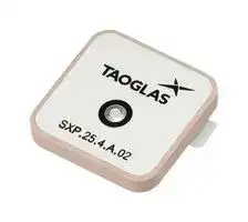
SXP.25.4.A.02
RF Antenna, 2.336 to 2.341GHz, Left Hand Circular, 6.16dBi, Adhesive / Pin
⚠️ Reference pricing provided. In case of supply shortages, we will connect you with our trusted procurement partners to ensure your project's continuity.
- Manufacturer: TAOGLAS
- Product type:
- Gain: 6.16dBi
- SVHC: No SVHC (21-Jan-2025)
- VSWR: -
- Input Power: 10W
- Antenna Type: Patch / SDARS
- Frequency Max: 2.341GHz
- Frequency Min: 2.336GHz
- Product Range: -
- Input Impedance: 50ohm
- Antenna Mounting: Adhesive / Pin
- Antenna Polarisation: Left Hand Circular
| Delivery and price | |
|---|---|
| Units per pack | 500 |
| Price | 1.3 € |
| Current stock | 100+ |
| Lead time | 30 days |
Datasheet

## ae TAOGLAS.

ed Ss Y) © 4+ ©

as" 4 of

»)

**Part No: SXP.25.4.A.02**

**Description**

SDARS 2320~2345MHz Dual-Band XM & Sirius Patch Antenna

**Features:**

SDARS (Satellite Digital Audio Radio Services) High Efficiency >85% across all bands Radiation pattern designed for XM & SIRIUS Requirements Optimized LHCP Radiation Pattern Pin & Adhesive Mounting Dims: 25 x 25 x 4mm RoHS & Reach Compliant

www.taoglas.com

SPE-25-8-109-B

**==> picture [358 x 218] intentionally omitted <==**

**----- Start of picture text -----**<br>
1. Introduction  3<br>2. Specification  4<br>3. Mechanical Drawing  6<br>4. Antenna Integration Guide  7<br>5. Packaging  13<br>6. Antenna Characteristics  14<br>7. Radiation Patterns  20<br>Changelog  37<br>**----- End of picture text -----**<br>


Taoglas makes no warranties based on the accuracy or completeness of the contents of this document and reserves the right to make changes to specifications and product descriptions at any time without notice. Taoglas reserves all rights to this document and the information contained herein. Reproduction, use or disclosure to third parties without express permission is strictly prohibited.

2

www.taoglas.com

SPE-25-8-109-B

The Taoglas SXP.25.4.A.02 is part of a series of high-efficiency patch antennas designed for use with Satellite Digital Audio Radio Services (SDARS). It features left-hand circular polarization and excellent gain characteristics in the 2320 to 2345 MHz band, making it compatible with the most popular satellite radio services available in many new vehicles.

The SXP.25 comes in a convenient, compact form factor, with dimensions of just 25mm x 25mm x 4mm, and is manufactured with high-quality ceramic. It is mounted via pin and 3M adhesive tape.

For further optimization to customer-specific device environments, custom tuned patch antennas can be supplied. Your regional Taoglas sales office can help you identify the best patch antenna for your specific SDARS application.

3

www.taoglas.com

SPE-25-8-109-B

|**SDARS Electrical**|**SDARS Electrical**|**SDARS Electrical**|**SDARS Electrical**|**SDARS Electrical**|**SDARS Electrical**|**SDARS Electrical**|**SDARS Electrical**|**SDARS Electrical**|
|---|---|---|---|---|---|---|---|---|
|**System**|**Frequency**<br>**(MHz)**|**Measurement**|**Measurement**<br>**Efficiency (%)**|**Efficiency (%)**<br>**Average Gain**<br>**(dB)**|**Average Gain**<br>**Peak Gain**<br>**(dBi)**|**Impedance**|**Polarization**|**Max. input power**|
|**XM**|2332.5-2345|100x100cm<br>Ground Plane|87.7|-0.57|5.11|50 Ω|LHCP|10W|
|||50x50cm<br>Ground Plane|93.8|-0.28|5.92||||
|||30x30cm<br>Ground Plane|87.4|-0.59|5.56||||
|||15x15cm<br>Ground Plane|Ground Plane<br>92.0|-0.36|6.16||||
|||7x7cm Ground<br>Plane|88.8|-0.52|5.69||||
|**SIRIUS**|2320-2332.5|100x100cm<br>Ground Plane|87.4|-0.59|5.11||||
|||50x50cm<br>Ground Plane|91.0|-0.41|5.92||||
|||30x30cm<br>Ground Plane|85.4|-0.69|5.48||||
|||15x15cm<br>Ground Plane|Ground Plane<br>87.9|-0.56|5.93||||
|||7x7cm Ground<br>Plane|87.8|-0.57|5.53||||


## **Mechanical**

||**Mechanical**|
|---|---|
|**Dimensions**|25mm x 25mm x 4mm|
|**Weight**|10g|
|**Material**|Ceramic|
|**Pin Diameter**|0.9±0.2mm|
|**Pin Length**|2.4±0.3mm|


||**Environmental**|**Environmental**|
|---|---|---|
|**Operation Temperature**||-40°C to 105°C|
|**Storage Temperature**||-40°C to 105°C|
|**Humidity**||Non-condensing 65°C 95% RH|


4

www.taoglas.com

SPE-25-8-109-B

## **XM Gain Requirements (Satellite) - Ground Plane (2338.75MHz)**

|**XM Gain Requirements(Satellite) - Ground Plane(2338.75MHz)**|**XM Gain Requirements(Satellite) - Ground Plane(2338.75MHz)**|**XM Gain Requirements(Satellite) - Ground Plane(2338.75MHz)**|**XM Gain Requirements(Satellite) - Ground Plane(2338.75MHz)**|**XM Gain Requirements(Satellite) - Ground Plane(2338.75MHz)**|**XM Gain Requirements(Satellite) - Ground Plane(2338.75MHz)**|**XM Gain Requirements(Satellite) - Ground Plane(2338.75MHz)**|**XM Gain Requirements(Satellite) - Ground Plane(2338.75MHz)**|**XM Gain Requirements(Satellite) - Ground Plane(2338.75MHz)**|**XM Gain Requirements(Satellite) - Ground Plane(2338.75MHz)**|**XM Gain Requirements(Satellite) - Ground Plane(2338.75MHz)**|**XM Gain Requirements(Satellite) - Ground Plane(2338.75MHz)**|
|---|---|---|---|---|---|---|---|---|---|---|---|
|||||||||||||
|||||||**Measured Average Gain (dBic)**||||||
|||||||||||||
|**Elevation**|**XM Sirius**|**7x7cm**||**15x15cm**||**30x30cm**||**50x50cm**||**100x100cm**||
|**Angle(degrees)**|**Limits (dBic)**|**Ground**||**Ground**||**Ground**||**Ground**||**Ground**||
|||Phi 0|Phi 90|Phi 0|Phi 90|Phi 0|Phi 90|Phi 0|Phi 90|Phi 0|Phi 90|
|||||||||||||
|**20 ≤ Ф ≤ 25**|0.5|0.1|0.2|0.2|-0.3|0.2|0.4|0.7|1.5|1.7|1.7|
|||||||||||||
|**25 ≤ Ф ≤ 30**|1|0.8|0.9|1.2|0.6|1.3|1.5|2.3|3.0|2.1|1.7|
|||||||||||||
|||||||||||||
|**30 ≤ Ф ≤ 50**|2|3.0|3.0|3.9|3.0|2.7|3.5|3.4|4.0|3.2|3.0|
|||||||||||||
|||||||||||||
|**50 ≤ Ф ≤ 70**|4|4.7|4.8|5.3|5.0|2.9|3.8|3.7|3.8|4.2|4.1|
|||||||||||||
|||||||||||||
|**70 ≤ Ф ≤ 90**|2|5.3|5.3|5.8|5.8|4.6|4.6|3.7|4.2|4.9|4.9|
|||||||||||||


## **XM Gain Requirements (Satellite) - Ground Plane (2326.25MHz)**

|**XM Gain Requirements(Satellite) - Ground Plane(2326.25MHz)**|**XM Gain Requirements(Satellite) - Ground Plane(2326.25MHz)**|**XM Gain Requirements(Satellite) - Ground Plane(2326.25MHz)**|**XM Gain Requirements(Satellite) - Ground Plane(2326.25MHz)**|**XM Gain Requirements(Satellite) - Ground Plane(2326.25MHz)**|**XM Gain Requirements(Satellite) - Ground Plane(2326.25MHz)**|**XM Gain Requirements(Satellite) - Ground Plane(2326.25MHz)**|**XM Gain Requirements(Satellite) - Ground Plane(2326.25MHz)**|**XM Gain Requirements(Satellite) - Ground Plane(2326.25MHz)**|**XM Gain Requirements(Satellite) - Ground Plane(2326.25MHz)**|**XM Gain Requirements(Satellite) - Ground Plane(2326.25MHz)**|**XM Gain Requirements(Satellite) - Ground Plane(2326.25MHz)**|
|---|---|---|---|---|---|---|---|---|---|---|---|
|||||||||||||
|||||||**Measured Average Gain (dBic)**||||||
|||||||||||||
|**Elevation**|**XM Sirius**|**7x7cm**||**15x15cm**||**30x30cm**||**50x50cm**||**100x100cm**||
|**Angle(degrees)**|**Limits (dBic)**|**Ground**||**Ground**||**Ground**||**Ground**||**Ground**||
|||Phi 0|Phi 90|Phi 0|Phi 90|Phi 0|Phi 90|Phi 0|Phi 90|Phi 0|Phi 90|
|**20 ≤ Ф ≤ 25**|0.5|0.0|0.7|0.0|0.9|0.1|1.0|0.8|2.0|1.9|1.3|
|||||||||||||
|**25 ≤ Ф ≤ 30**|1|0.9|1.4|1.0|1.8|1.3|2.0|2.5|3.4|2.2|1.5|
|||||||||||||
|**30 ≤ Ф ≤ 50**|2|3.1|3.3|3.6|4.1|3.1|3.6|4.1|4.3|3.3|3.0|
|||||||||||||
|**50 ≤ Ф ≤ 70**|4|4.8|5.0|5.5|5.6|3.7|3.7|4.3|4.5|4.3|4.3|
|||||||||||||
|||||||||||||
|**70 ≤ Ф ≤ 90**|2|5.5|5.5|6.1|6.1|4.6|4.6|4.4|4.6|4.6|4.7|
|||||||||||||


## **XM Gain Requirements (Terrestrial)- Ground Plane Antenna Mean Passive VP Gain Over Solid Angle (dBi)**

|**XM Gain Requirements (Terrestrial)- Ground Plane**<br>**Antenna Mean Passive VP Gain Over Solid Angle(dBi)**|**XM Gain Requirements (Terrestrial)- Ground Plane**<br>**Antenna Mean Passive VP Gain Over Solid Angle(dBi)**|**XM Gain Requirements (Terrestrial)- Ground Plane**<br>**Antenna Mean Passive VP Gain Over Solid Angle(dBi)**|**XM Gain Requirements (Terrestrial)- Ground Plane**<br>**Antenna Mean Passive VP Gain Over Solid Angle(dBi)**|**XM Gain Requirements (Terrestrial)- Ground Plane**<br>**Antenna Mean Passive VP Gain Over Solid Angle(dBi)**|**XM Gain Requirements (Terrestrial)- Ground Plane**<br>**Antenna Mean Passive VP Gain Over Solid Angle(dBi)**|**XM Gain Requirements (Terrestrial)- Ground Plane**<br>**Antenna Mean Passive VP Gain Over Solid Angle(dBi)**|**XM Gain Requirements (Terrestrial)- Ground Plane**<br>**Antenna Mean Passive VP Gain Over Solid Angle(dBi)**|**XM Gain Requirements (Terrestrial)- Ground Plane**<br>**Antenna Mean Passive VP Gain Over Solid Angle(dBi)**|**XM Gain Requirements (Terrestrial)- Ground Plane**<br>**Antenna Mean Passive VP Gain Over Solid Angle(dBi)**|**XM Gain Requirements (Terrestrial)- Ground Plane**<br>**Antenna Mean Passive VP Gain Over Solid Angle(dBi)**|**XM Gain Requirements (Terrestrial)- Ground Plane**<br>**Antenna Mean Passive VP Gain Over Solid Angle(dBi)**|
|---|---|---|---|---|---|---|---|---|---|---|---|
|||||||||||||
|||||**Measured Average Gain (dBic)**||||||||
|||||||||||||
||**Elevation Angle**|**7x7cm**||**15x15cm**||**30x30cm**||**50x50cm**||**100x100cm**||
|**AUT Location**|<br>**(degrees)**|**Ground**||**Ground**||**Ground**||**Ground**||**Ground**||
|||**2326.25**|**2338.75**|**2326.25**|**2338.75**|**2326.25**|**2338.75**|**2326.25**|**2338.75**|**2326.25**|**2338.75**|
|||**MHz**|**MHz**|**MHz**|**MHz**|**MHz**|**MHz**|**MHz**|**MHz**|**MHz**|**MHz**|
|**Passive Ground**||||||||||||
||0 ≤ Ф ≤ 10|3.8|3.5|3.8|4.7|2.3|3.3|2.3|3.3|2.8|3.1|
|**Plane**||||||||||||
|||||||||||||


## **XM Gain Requirements (Terrestrial)- Ground Plane Antenna P/P Gain variation(dB)**

|**XM Gain Requirements (Terrestrial)- Ground Plane**<br>**Antenna P/P Gain variation(dB)**|**XM Gain Requirements (Terrestrial)- Ground Plane**<br>**Antenna P/P Gain variation(dB)**|**XM Gain Requirements (Terrestrial)- Ground Plane**<br>**Antenna P/P Gain variation(dB)**|**XM Gain Requirements (Terrestrial)- Ground Plane**<br>**Antenna P/P Gain variation(dB)**|**XM Gain Requirements (Terrestrial)- Ground Plane**<br>**Antenna P/P Gain variation(dB)**|**XM Gain Requirements (Terrestrial)- Ground Plane**<br>**Antenna P/P Gain variation(dB)**|**XM Gain Requirements (Terrestrial)- Ground Plane**<br>**Antenna P/P Gain variation(dB)**|**XM Gain Requirements (Terrestrial)- Ground Plane**<br>**Antenna P/P Gain variation(dB)**|**XM Gain Requirements (Terrestrial)- Ground Plane**<br>**Antenna P/P Gain variation(dB)**|**XM Gain Requirements (Terrestrial)- Ground Plane**<br>**Antenna P/P Gain variation(dB)**|**XM Gain Requirements (Terrestrial)- Ground Plane**<br>**Antenna P/P Gain variation(dB)**|**XM Gain Requirements (Terrestrial)- Ground Plane**<br>**Antenna P/P Gain variation(dB)**|
|---|---|---|---|---|---|---|---|---|---|---|---|
|||||||||||||
|||||**Measured Average Gain (dBic)**||||||||
|||||||||||||
||**Elevation Angle**|**7x7cm**||**15x15cm**||**30x30cm**||**50x50cm**||**100x100cm**||
|**AUT Location**|<br>**(degrees)**|**Ground**||**Ground**||**Ground**||**Ground**||**Ground**||
|||**2326.25**|**2338.75**|**2326.25**|**2338.75**|**2326.25**|**2338.75**|**2326.25**|**2338.75**|**2326.25**|**2338.75**|
|||**MHz**|**MHz**|**MHz**|**MHz**|**MHz**|**MHz**|**MHz**|**MHz**|**MHz**|**MHz**|
|**Passive Ground**||||||||||||
||Ф ≤ 5|0.05|0.05|0.05|0.08|0.22|0.26|0.14|0.09|0.17|0.25|
|**Plane**||||||||||||
|||||||||||||


5

www.taoglas.com

SPE-25-8-109-B

6

www.taoglas.com

SPE-25-8-109-B

The following is an example on how to integrate the SXP.25.4.A.02 into a design. The SXP.25.4.A.02 has one pin which is used for the RF Feed. Taoglas recommends using a minimum of 70x70mm ground plane to ensure optimal performance.

Top view of an example 70x70mm PCB Reference Design.

7

www.taoglas.com

SPE-25-8-109-B

## **4.1** Schematic Symbol and Pin Definitions ay

Top view of an example 70x70mm PCB Reference Design.

The circuit symbol for a SXP.25.4.A.02 is shown below. The antenna has 1 pin as indicated below.

## TAOGLAS_SXP.25.4.A.02

ANT1

- Pin Description

- ~~i~~ 1 RF Feed

Above is a schematic symbol of the SXP.25.4.A.02 and a table of the pin definitions.

8

www.taoglas.com

SPE-25-8-109-B

## **4.2** Antenna Footprint 2

**==> picture [411 x 217] intentionally omitted <==**

**----- Start of picture text -----**<br>
BOTTOM<br>TOP<br>Pin  Description<br>[LE<br>1  RF Feed<br>**----- End of picture text -----**<br>


9

www.taoglas.com

SPE-25-8-109-B

## **4.3** Copper Clearance =

The footprint and clearance on the PCB must comply with the antenna’s specification. The PCB layout shown in the diagrams below demonstrates the SXP.25.4.A.02 clearance area for Pin 1 (RF Feed Pad). The bottom copper keep out area only applies to the bottom layer and the top copper keep out area applies to all other layers.

There should be a Ø3mm copper clearance around the antenna pins on the top side of the PCB with a Ø3.5mm copper clearance around the antenna pins on the bottom side.

TOP SIDE

BOTTOM SIDE

2D Images of Copper Clearances for the SXP.25.4.A.02

10

www.taoglas.com

SPE-25-8-109-B

## Antenna Integration

The SXP.25.4.A.02 should be placed in the centre of the PCB to take advantage of the ground plane. The RF traces must maintain a 50 Ohm transmission line. Ground vias should be placed around the copper clearance area and the transmission line. Note that depending on the design application, tuning may be required for optimal performance. This may be achieved using a ‘pi’ matching network or custom tuning of the patch antenna.

Bottom view of the PCB Reference Design, showing transmission lines and integration notes.

11

www.taoglas.com

SPE-25-8-109-B

## Final Integration

The bottom side image shown below highlights the antenna transmission line. Taoglas recommends using a minimum of 70x70mm ground plane to ensure optimal performance.

Top Side (70x70mm example PCB Reference Design)

Bottom Side

12

www.taoglas.com

SPE-25-8-109-B

13

www.taoglas.com

SPE-25-8-109-B

## Return Loss

## VSWR

14

www.taoglas.com

SPE-25-8-109-B

## Efficiency

## Average Gain

15

www.taoglas.com

SPE-25-8-109-B

## Peak Gain

## Axial Ratio

16

www.taoglas.com

SPE-25-8-109-B

## AR vs Angle for Phi=0 (Satellite)

**==> picture [287 x 282] intentionally omitted <==**

**----- Start of picture text -----**<br>
°° TMLn<br>ig HI te<br>WMT | |A<br>io HA We<br>DG OeNRRLae<br>aa HOE<br>S47 AME A | TT TT AN<br>SO" ME ATA<br>Sig INE TATA TT tT UA TA<br>mM HWA TAY | | AAT OT Vn<br>Sg TT<br>< JING MT WAL TTAT<br>THEW INURE NAL TT | A<br>6 EAM EN ee<br>PWIVOIRETE EAT<br>4 ee A INANE TT NT<br>HEL | A A RRA ee | PT<br>>Mi i Met tt Wha eA TN<br>IEEE. ieee<br>oLtlilit | | |] WN Pe t t etit<br>-180 -150 -120 -90 -60 -30 0) 30 60 90 120 150<br>Theta (°)<br>————= 100x100cm Ground Plane_SXM High Band* <== 50x50cm Ground Plane_SXM High Band*<br>(Satellite) (Satellite)<br>—ene Plane_SXM High Band* ——anne Plane _SXM High Band<br>**----- End of picture text -----**<br>


## AR vs Angle for Phi=0 (Terrestrial)

17

www.taoglas.com

SPE-25-8-109-B

## AR vs Angle for Phi=90 (Satellite)

**==> picture [271 x 225] intentionally omitted <==**

**----- Start of picture text -----**<br>
°° TONLLL<br>ig A<br>PYAS| 0<br>16 UM<br>ia IMM [AOU] TAA Tt<br>@ > PYMRR TY)YAAN<br>Ss WME UT AN TT [PN]<br>Sig WW WIN TN |<br><M AT TA |NE<br>Sg IMA | WW tt AA<br><= WE A a<br>6 MIN TAAL Tt ea<br>WY NAW Neen | ACA TAT<br>a WIA ENYA TPP<br>00 AZ Se NER eee ell |<br>> NSBRBEA |EREENANARI 4)*. vySee.| AAT<br>o LLL ttt ti ty | MV INTTe<br>-180 -150 -120 -90 -60 -30 0) 30 60 90 120 150<br>Theta (°)<br>**----- End of picture text -----**<br>


## AR vs Angle for Phi=90 (Terrestrial)

**==> picture [262 x 13] intentionally omitted <==**

**----- Start of picture text -----**<br>
*° TTLL<br>**----- End of picture text -----**<br>


18

www.taoglas.com

SPE-25-8-109-B

## AR vs Angle for Teata=0 (Satellite)

**==> picture [266 x 201] intentionally omitted <==**

**----- Start of picture text -----**<br>
°° TOLL LLL<br>iw tA A Pe |<br>LT VAIN A PAA A TA OA<br>16 (A-A YN AVR Ne TN IZ AY<br>Yi Why NL | PAN AT TA NI TU<br>wu iNAPNAANUAT ANALY et<br>@y WidBGWN Se PN 2TAi)NALNP ee<br>Oe ReLeINLAY<br>Sig i<br>a WAI AT TT Ye<br>Sell TM NAL Ae taEM<br>ee lt ivy (Ft TAT FT] ALT eT TT<br>ee eee eee ee eee<br>6 MALT TAA | er ONY<br>PNET AT Peet IN MA Te<br>attAlLi IVa i ti tt NY TT<br>PT IN TT IAT A A<br>>LtLtT ALi AT Tt tt tt PINE 7<br>Pi TIN ATT PE<br>oLtti Mit TT TT Ete tet et et te<br>**----- End of picture text -----**<br>


## AR vs Angle for Theta=90 (Terrestrial)

19

www.taoglas.com

SPE-25-8-109-B

## Test Setup

**==> picture [471 x 10] intentionally omitted <==**

**----- Start of picture text -----**<br>
7x7cm Ground Plane  15x15cm Ground Plane  30x30cm Ground Plane<br>**----- End of picture text -----**<br>


**==> picture [118 x 8] intentionally omitted <==**

**----- Start of picture text -----**<br>
100x100cm Ground Plane<br>**----- End of picture text -----**<br>


**==> picture [107 x 9] intentionally omitted <==**

**----- Start of picture text -----**<br>
50x50cm Ground Plane<br>**----- End of picture text -----**<br>


20

www.taoglas.com

SPE-25-8-109-B

## 100x100cm Ground Plane Patterns at 2326 MHz

## XZ Plane

## YZ Plane

## XY Plane

21

www.taoglas.com

SPE-25-8-109-B

## 50x50cm Ground Plane Patterns at 2326 MHz

## XZ Plane

## YZ Plane

## XY Plane

22

www.taoglas.com

SPE-25-8-109-B

## 30x30cm Ground Plane Patterns at 2326 MHz

## XZ Plane

## YZ Plane

## XY Plane

23

www.taoglas.com

SPE-25-8-109-B

## 15x15cm Ground Plane Patterns at 2326 MHz

## XZ Plane

## YZ Plane

## XY Plane

24

www.taoglas.com

SPE-25-8-109-B

## 7x7cm Ground Plane Patterns at 2326 MHz

**==> picture [397 x 9] intentionally omitted <==**

**----- Start of picture text -----**<br>
XZ Plane  YZ Plane  XY Plane<br>**----- End of picture text -----**<br>


25

www.taoglas.com

SPE-25-8-109-B

## 100x100cm Ground Plane Patterns at 2339 MHz

## XZ Plane

## YZ Plane

## XY Plane

26

www.taoglas.com

SPE-25-8-109-B

## 50x50cm Ground Plane Patterns at 2339 MHz

## XZ Plane

## YZ Plane

## XY Plane

27

www.taoglas.com

SPE-25-8-109-B

## 30x30cm Ground Plane Patterns at 2339 MHz

## XZ Plane

## YZ Plane

## XY Plane

28

www.taoglas.com

SPE-25-8-109-B

## 15x15cm Ground Plane Patterns at 2339 MHz

## XZ Plane

## YZ Plane

**==> picture [44 x 9] intentionally omitted <==**

**----- Start of picture text -----**<br>
XY Plane<br>**----- End of picture text -----**<br>


29

www.taoglas.com

SPE-25-8-109-B

## 7x7cm Ground Plane Patterns at 2339 MHz

## XZ Plane

## YZ Plane

## XY Plane

30

www.taoglas.com

SPE-25-8-109-B

## 100x100cm Ground Plane Patterns at 2332 MHz

## XZ Plane

## YZ Plane

## XY Plane

31

www.taoglas.com

SPE-25-8-109-B

## 50x50cm Ground Plane Patterns at 2332 MHz

## XZ Plane

## YZ Plane

## XY Plane

32

www.taoglas.com

SPE-25-8-109-B

## 30x30cm Ground Plane Patterns at 2332 MHz

## XZ Plane

## YZ Plane

## XY Plane

33

www.taoglas.com

SPE-25-8-109-B

## 15x15cm Ground Plane Patterns at 2332 MHz

## XZ Plane

## YZ Plane

## XY Plane

34

www.taoglas.com

SPE-25-8-109-B

## 7x7cm Ground Plane Patterns at 2332 MHz

## XZ Plane

## YZ Plane

## XY Plane

35

www.taoglas.com

SPE-25-8-109-B

## Changelog for the datasheet

## **SPE-25-8-109 – SXP.25.4.A.02**

## **Revision: B (Current Version)**

Date: 2026-04-07 Notes: Updated performance table. Author: Paul Liu

**Previous Revisions**

## **Revision: A**

Date: 2025-04-02 Notes: Initial Release

Author: Gary West

36

www.taoglas.com

SPE-25-8-109-B

37

www.taoglas.com

SPE-25-8-109-B
Updated at June 9, 2026
About Novapart
Novapart is a B2B electronic component broker specialising in stock shortages and cost reduction. We source hard-to-find parts and identify compliant alternatives across a catalogue of 410,000+ components from 500+ manufacturers.
Learn more →Stock Shortage Specialist
When a component is unavailable, discontinued or has an unacceptable lead time, we tap into our network of vetted European and Asian distributors to source what you need — without compromising on quality or traceability.
Request a quote →Compliant Alternatives
We identify pin-to-pin, electrically equivalent substitutes that meet the same certifications (RoHS, AEC-Q100, REACH) as your original specification — validated against datasheets, not just part numbers. Often at a lower cost.
BOM Analysis service →