
Image not available
Illustrative purposes only

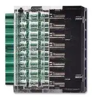
SWD4-8MF2
Plugs, Smartwire-DT, Flat, Blade Terminals, 8 Positions
⚠️ Reference pricing provided. In case of supply shortages, we will connect you with our trusted procurement partners to ensure your project's continuity.
- Manufacturer: EATON MOELLER
- Product type: Controller Accessories
- Current Rating:-; Product Range:-; SVHC:No SVHC (17-Dec-2015); Accessory Type:Blade Terminal; For Use With:Smartwire Darwin Communication Systems
- SVHC: No SVHC (17-Dec-2015)
- Product Range: -
- Current Rating: -
| Delivery and price | |
|---|---|
| Units per pack | 2500 |
| Price | 1.04 € |
| Current stock | 10+ |
| Lead time | 30 days |
Datasheet

## Connectivity Solutions

## **SmartWire-DT**

**XV Series HMI-PLC with SmartWire-DT**

## **Machine Mount (IP67) I/O Modules**

## **9.1 SmartWire-DT In Panel and On Machine Wiring Solution**

**==> picture [331 x 594] intentionally omitted <==**

**----- Start of picture text -----**<br>
|||
|---|---|
|System Overview|
|System Components  . . . . . . . . . . . . . . . . . . . . . . . . . . . . . . . . . . .|V7-T9-4|
|System Overview Diagram . . . . . . . . . . . . . . . . . . . . . . . . . . . . . . .|V7-T9-6|
|Gateway Modules and System Controllers|
|System Control Overview . . . . . . . . . . . . . . . . . . . . . . . . . . . . . . . .|V7-T9-10|
|Gateway Modules . . . . . . . . . . . . . . . . . . . . . . . . . . . . . . . . . . . . . .|V7-T9-11|
|XV Series HMI-PLC with SmartWire-DT . . . . . . . . . . . . . . . . . . . . .|V7-T9-12|
|XC152 Series PLC with SmartWire-DT . . . . . . . . . . . . . . . . . . . . . .|V7-T9-12|
|easy802/806 Programmable Relays with SmartWire-DT  . . . . . . . .|V7-T9-13|
|I/O and Powerfeed Modules, System Connectivity Components|
|Powerfeed Modules  . . . . . . . . . . . . . . . . . . . . . . . . . . . . . . . . . . . .|V7-T9-15|
|I/O Modules  . . . . . . . . . . . . . . . . . . . . . . . . . . . . . . . . . . . . . . . . . .|V7-T9-15|
|System Connectivity Components . . . . . . . . . . . . . . . . . . . . . . . . .|V7-T9-16|
|Motor Control Modules|
|Product Identification  . . . . . . . . . . . . . . . . . . . . . . . . . . . . . . . . . . .|V7-T9-19|
|XTPE Electronic Manual Motor Protectors . . . . . . . . . . . . . . . . . . .|V7-T9-20|
|XTCE Contactor Modules . . . . . . . . . . . . . . . . . . . . . . . . . . . . . . . .|V7-T9-23|
|EMS Electronic Motor Starters . . . . . . . . . . . . . . . . . . . . . . . . . . . .|V7-T9-26|
|DS7 Soft Start Controllers . . . . . . . . . . . . . . . . . . . . . . . . . . . . . . . .|V7-T9-27|
|DE1 Variable Speed Starters . . . . . . . . . . . . . . . . . . . . . . . . . . . . . .|V7-T9-28|
|DC1 Variable Frequency Drives . . . . . . . . . . . . . . . . . . . . . . . . . . . .|V7-T9-30|
|DA1 Variable Frequency Drives . . . . . . . . . . . . . . . . . . . . . . . . . . . .|V7-T9-32|
|Pilot Device Modules|
|M22 Contact and LED Modules . . . . . . . . . . . . . . . . . . . . . . . . . . .|V7-T9-34|
|M22 Control Stations (8-Conductor)  . . . . . . . . . . . . . . . . . . . . . . . .|V7-T9-37|
|Stacklight Base Modules with SmartWire-DT|
|SL4 and SL7 Stacklight Base Modules . . . . . . . . . . . . . . . . . . . . . .|V7-T9-40|
|Machine Mount Components|
|Machine Mount I/O Modules—Digital  . . . . . . . . . . . . . . . . . . . . . .|V7-T9-43|
|Machine Mount I/O Modules—Analog . . . . . . . . . . . . . . . . . . . . . .|V7-T9-45|
|I/O Splitters . . . . . . . . . . . . . . . . . . . . . . . . . . . . . . . . . . . . . . . . . . .|V7-T9-46|
|Other I/O Connections  . . . . . . . . . . . . . . . . . . . . . . . . . . . . . . . . . .|V7-T9-46|
|Valve Connectors  . . . . . . . . . . . . . . . . . . . . . . . . . . . . . . . . . . . . . .|V7-T9-47|
|Machine Mount Powerfeed Modules  . . . . . . . . . . . . . . . . . . . . . . .|V7-T9-47|
|Panel Transition Components . . . . . . . . . . . . . . . . . . . . . . . . . . . . .|V7-T9-48|
|SmartWire-DT Round Bus Cables . . . . . . . . . . . . . . . . . . . . . . . . . .|V7-T9-49|
|Other System Components  . . . . . . . . . . . . . . . . . . . . . . . . . . . . . .|V7-T9-52|
|Enclosed (IP67) Pilot Devices|
|Enclosed M22 Pilot Device Examples . . . . . . . . . . . . . . . . . . . .|V7-T9-54|
|Enclosures . . . . . . . . . . . . . . . . . . . . . . . . . . . . . . . . . . . . . . . . .|V7-T9-54|
|M12 Wiring Receptacles  . . . . . . . . . . . . . . . . . . . . . . . . . . . . . .|V7-T9-54|
|Remote Machine Mount Stacklights|
|Stacklight Mounting Modules—Fast Mounting System  . . . . . .|V7-T9-56|
|Stacklight Mounting Modules—Post Mounting System  . . . . . .|V7-T9-57|
|Technical Data and Specifications  . . . . . . . . . . . . . . . . . . . . . . . . . . . .|V7-T9-58|
|Dimensions  . . . . . . . . . . . . . . . . . . . . . . . . . . . . . . . . . . . . . . . . . . . . .|V7-T9-102|

**----- End of picture text -----**<br>


**9**

**Volume 7—Logic Control, Operator Interface and Connectivity Solutions** CA08100008E—January 2017 www.eaton.com

**V7-T9-1**

## Revision notes

Volume 7—Logic Control, Operator Interface and Connectivity Solutions, CA08100008E

Tab 9—Connectivity Solutions

|**Revision date**|**Section**|**Change page(s)**|**Description**|
|---|---|---|---|
|01/16/2017|9.1|V7-T9-26|Content edit|
|01/16/2017|9.1|V7-T9-65|Content edit|


**==> picture [140 x 45] intentionally omitted <==**

Connectivity Solutions

9.1

SmartWire-DT In Panel and On Machine Wiring Solution

## **SmartWire-DT In Panel and On Machine Wiring Solution**

## **Contents**

|**Contents**||
|---|---|
|**_Description_**|**_Page_**|
|System Overview||
|Features  . . . . . . . . . . . . . . . . . . . . . . . . . . .|**V7-T9-3**|
|Standards and Certifications . . . . . . . . . . . .|**V7-T9-3**|
|System Components  . . . . . . . . . . . . . . . . . . . . . .|**V7-T9-4**|
|System Overview Diagram . . . . . . . . . . . . . . . . . .|**V7-T9-6**|


**9**

## **System Overview**

## **Product Description**

The SmartWire-DT[®] In Panel and On Machine wiring system uses a single green cable inside a machine control cabinet and across the machine itself to connect motor starters, variable frequency drives, soft starters, pushbuttons, sensors, pneumatic and hydraulic valves, stacklights and other indicator lights.

Inside the machine control cabinet the continuous SmartWire-DT green cable is flat. The flat cable connects directly to in panel motor starters, variable frequency drives, soft starters, panel-mounted pushbutton actuators, stacklights and other indicator lights. It eliminates the need for most of the conventional point-to-point control wiring done in a traditionally wired control panel—and even integrates 24 Vdc control

power for contactor coils on the single SmartWire-DT cable. The start of the SmartWire-DT system is either an Eaton PLC or a combination HMI/PLC with SmartWire-DT embedded or a simple gateway.

These SmartWire-DT gateways establish the connection between a SmartWire-DT system and standard programmable logic controller (PLC) fieldbuses, such as EtherNet/IP, Modbus TCP, EtherCAT, PROFINET, POWERLINK, PROFIBUS DP and CANopen. The gateway works without any conventional PLC I/O required because SmartWire-DT directly integrates the input/output (I/O) level in the switching devices.

Inside the control cabinet, typical faults such as loose connections and miswired terminations are eliminated using the flat cable and the specialized connectors. Outside the cabinet on the machine, the SmartWire-DT machine mount I/O modules connect using industry standard keyed M12 connectors to eliminate the possibility of miswiring. Further, dramatic wiring reductions are possible given the single SmartWire-DT cable connection that brings 24 Vdc power to and carries signals to and from devices.

Each SmartWire-DT machine mount I/O module has diagnostic LEDs built in, reducing commissioning time and troubleshooting in the field.

Nodes on the SmartWire-DT network both inside and outside the main control cabinet are automatically assigned addresses by the gateway or the HMI/PLC device with the simple push of a button—assigning addresses in the order that the nodes are connected. The system employs time monitoring and a watchdog timeout using the established target configuration as a reference—safely monitoring the integrity of the control scheme. SmartWire-DT has a maximum network length of 2000 feet and can connect up to 99 nodes per gateway. A software program called SWD-Assist enables the layout, planning and system configuration of a SmartWire-DT network.

**Volume 7—Logic Control, Operator Interface and Connectivity Solutions** CA08100008E—January 2017 www.eaton.com

**V7-T9-2**

Connectivity Solutions

9.1

SmartWire-DT In Panel and On Machine Wiring Solution

## **Features**

Connects directly to:

- XTPE electronic manual motor protectors

- XTCE contactors

- XTRE control relays

- Electronic motor starters

- DS7 soft start controllers

- DE1 variable speed starters

- DC1 VFDs

- DA1 VFDs

- M22 pilot devices

- SL4 and SL7 stacklights

- On Machine devices including sensors, limit switches, pneumatic and hydraulic valves, remote contactors, pushbuttons, stacklights and other command and control components

Gateways support fieldbus integration, including:

- EtherNet/IP

- Modbus TCP

- EtherCAT

- PROFINET

- POWERLINK

- PROFIBUS DP

- CANopen

- Supports up to 99 nodes (58 nodes when connected to PROFIBUS DP Gateway)

- Automatically assigns node addresses

- Integrates and supplies 24 Vdc power to contactor coils

- Includes diagnostic bi-color LEDs on each node connection

## **Standards and Certifications**

- UL listed

- UL tested to Canadian safety standards

- CE Certified

- RoHS compliant

**9**

**Volume 7—Logic Control, Operator Interface and Connectivity Solutions** CA08100008E—January 2017 www.eaton.com

**V7-T9-3**

Connectivity Solutions

9.1

SmartWire-DT In Panel and On Machine Wiring Solution

**==> picture [58 x 8] intentionally omitted <==**

**----- Start of picture text -----**<br>
System Components<br>**----- End of picture text -----**<br>


## **Contents**

|**Contents**||
|---|---|
|**_Description_**|**_Page_**|
|System Components||
|System Overview  . . . . . . . . . . . . . . . . . . . .|**V7-T9-2**|
|System Overview Diagram . . . . . . . . . . . . .|**V7-T9-6**|


**9**

## **System Components**

## **Product Description**

The start of the SmartWire-DT system is usually a gateway module connected to a PLC or controller fieldbus. This means that SmartWire-DT connected components will work with most third-party PLCs without having to create a new program. These devices are typically located within the main control cabinet for a machine.

To plan and lay out a SmartWire-DT network, an MS Windows-compatible software program called SWD-Assist is available as a free download from the Eaton website. The SWD-Assist configuration software allows a user to drag-and-drop system components like motor starters, drives, pushbuttons and indicator lights, and will calculate the control power requirements needed and generate a bill of materials of all the required SmartWire-DT components.

## _**In Panel Components**_

## **Gateway Modules**

Gateway modules connect the SmartWire-DT system to the PLC. They are connected as nodes to the existing PLC fieldbus and are the start of the SmartWire-DT connection system. Gateways are available with EtherNet/IP, Modbus TCP, EtherCAT, PROFINET, POWERLINK, PROFIBUS DP and CANopen protocols.

## **System Controllers**

In the event that the Gateway module plus third-party PLC architecture is not used, system controllers from Eaton can operate a SmartWire-DT system. System controllers include an integrated SmartWire-DT gateway and are available as PLCs or HMI-PLCs using a CoDeSys programming platform or as programmable relays using simple ladder logic programming.

## **Motor Control Modules**

Contactor modules fit into standard XT contactors and control relays directly on top, in place of a top-mounted auxiliary contact block. The modules fit all XTCE size B and C frame contactors and XTRE control relays.

Variable Speed Starters and Variable Frequency Drives connect to the SmartWire-DT system with plug-in modules similar to the approach with contactor modules.

Soft Start Controllers and Electronic Motor Starters with built-in SmartWire-DT functionality connect directly to the SmartWire-DT flat cable without the need for a supplemental module.

## **Pilot Device Modules**

Pilot device modules fit into standard M22 pilot devices in both front-mount and base-mount configurations and replace the standard contact block and light units. Single and double contact modules with and without LEDs are available to meet a wide variety of control circuit requirements.

## **Stacklight Base Modules**

Stacklight modules connect SL4 and SL7 Series stacklights when mounted to the control cabinet with Eaton’s Fast Mount Base. A variety of incandescent, LED, high- power LED and audible signal modules are available to meet machine indication requirements.

To download the SWD-Assist configuration software, visit www.eaton.com/smartwiredt.

**Volume 7—Logic Control, Operator Interface and Connectivity Solutions** CA08100008E—January 2017 www.eaton.com

**V7-T9-4**

Connectivity Solutions

9.1

SmartWire-DT In Panel and On Machine Wiring Solution

## _**In Panel Components**_

## **Digital and Analog I/O Modules**

Digital and analog I/O modules are connected as nodes on the SmartWire-DT network and allow standard or generic devices to be connected to the SmartWire-DT system. They can be connected anywhere along the flat cable network and can therefore be positioned in the control panel to help reduce I/O wiring.

## **Powerfeed Modules**

Powerfeed modules feed auxiliary 24 Vdc power and/or 15 Vdc network power into the SmartWire-DT flat cable. The auxiliary 24 Vdc power is needed for the power supply of contactors and the 15 Vdc network power is used for supplying power to additional SmartWire-DT nodes. Powerfeed modules are also used to create zone control or groups of devices controlled by a single Emergency Stop.

## **SmartWire-DT Flat Cable**

The flat cable is an 8-conductor cable that is flexible, durable and rated for 600 V so that it can be placed in the panel wiring duct along with 480 V or 600 V power conductors. It has two prominent features: (a) arrows indicating the front of the cable and the direction away from the gateway and (b) black edging indicating the polarity of the flat cable, the 15 Vdc wire and the reference mark for installing the device plugs and flat plugs.

## _**On Machine Components**_

At the edge of the control cabinet the SmartWire-DT system transitions from the 8-conductor flat cable to a 5-conductor round cable with standard DC M12 barrel connectors, using simple transition adapters that mount through the panel wall.

## **SmartWire-DT Round Cable**

The round cable has 5 conductors, uses standard DC M12 barrel connectors, and is 300 V rated. It is used outside the control panel to connect SmartWire-DT machine mount I/O modules to the SmartWire-DT system for use with peripherals such as sensors, enclosed pushbuttons, pneumatic and hydraulic valves, stacklights and other remote devices. This single cable is used both to provide power to connected devices and to carry I/O signals.

## **Machine Mount I/O Modules**

Machine mountable I/O modules are connected as nodes on the SmartWire-DT network and allow standard or generic devices to be connected to the SmartWire-DT system. They are suitable for washdown environments and can be connected anywhere around the machine with up to 2000 feet and 99 devices possible with a single cable connection.

## **Accessory Cables**

A variety of accessory cables are available to make the connection between remote devices (including sensors, stacklights, hydraulic and pneumatic valves, enclosed pilot devices, and other command and control devices) and the SmartWire-DT machine mounted I/O modules.

## **Enclosed Pilot Device Stations**

Pilot device modules mounted in IP67 enclosures for use in remote machine locations can be assembled from standard components supplied by Eaton, and contacts can be wired for direct connection to a SmartWire-DT machine mount I/O module using a standard device accessory cable as described in the section above. Examples of such devices include pilot lights, pushbuttons, illuminated pushbuttons, selector switches and key switches.

## **Remote Stacklights**

Stacklights for use in remote machine locations can be assembled from standard components supplied by Eaton with contacts wired for direct connection to a SmartWire-DT machine mount I/O module using a standard device accessory cable.

## **Machine Mount Powerfeed Modules**

> Powerfeed modules feed 4 A **9** of auxiliary 24 Vdc power into the SmartWire-DT round cable when needed to **9** supply power to additional

> SmartWire-DT nodes. Eaton’s **9** SWD-Assist software can be

> used to quickly and easily **9** calculate the need for

> Powerfeed modules in a **9** round cable system.

## **Other System Accessories**

Other accessories for the SmartWire-DT system include connectors, jumpers, bushings, plugs and sockets, terminating resistors and crimping tools.

**Volume 7—Logic Control, Operator Interface and Connectivity Solutions** CA08100008E—January 2017 www.eaton.com

**V7-T9-5**

Connectivity Solutions

9.1

SmartWire-DT In Panel and On Machine Wiring Solution

## **System Overview Diagram**

## **SmartWire-DT Contactor Modules**

**==> picture [436 x 575] intentionally omitted <==**

**----- Start of picture text -----**<br>
6 6 4 6<br>9 7 10 10 10 12<br>a, /<br>9<br>9<br>9 3 4 5<br>2 6<br>9 _ 1 8 9 11 2 950)<br>9 17 19 20<br>55 16<br>9<br>14<br>9 6<br>15<br>13<br>9 15 18<br>56 10 10<br>9 10<br>10 10<br>MA gf egl 10<br>9<br>9 7 21 23 2423 26<br>22 26 53<br>9 22 25 23 54<br>6 10 6<br>9 6 27 10 10 6<br>10<br>7 28<br>9 30<br>6 35<br>9<br>47<br>6<br>32<br>9 34<br>36<br>48 29 /—> y 33 \<br>9 = 24 26 34<br>/ LY, SIE<br>31 35 45<br>9 37<br>9 26<br>40 44<br>41<br>9 41<br>9 39<br>PS <, Ss BOG 7 | f<br>9<br>38 42<br>6<br>9 39 43<br>7 6<br>9 10 10 46<br>49 50 51 10<br>9 \ yeaey 49 50 10 / )mn: a|<br>49 10<br>52<br>**----- End of picture text -----**<br>


**Volume 7—Logic Control, Operator Interface and Connectivity Solutions**

**V7-T9-6**

CA08100008E—January 2017 www.eaton.com

Connectivity Solutions

9.1

SmartWire-DT In Panel and On Machine Wiring Solution

|**Item**<br>**Number Description**<br>**1**<br>SmartWire-DT PLC XC-152<br>**2**<br>SmartWire-DT HMI-PLC<br>**3**<br>PLC with field bus interface<br>**4**<br>SmartWire-DT Gateways<br>**5**<br>Control relay easy800 with SmartWire-DT<br>**6**<br>SmartWire-DT blade terminal, 8-pole<br>**7**<br>SmartWire-DT 8-pin ribbon cable<br>**8**<br>SmartWire-DT I/O module<br>**9**<br>SmartWire-DT module for miniature circuit-breakers and residual-current<br>circuit breakers<br>**10**<br>SmartWire-DT external device plug, 8-pole<br>**11**<br>SmartWire-DT connection for NZM<br>**12**<br>NZM circuit-breakers<br>**13**<br>SmartWire-DT contactor module<br>**14**<br>DILM contactor<br>**15**<br>SmartWire-DT contactor module with Hand-0ff-Automatic switch<br>**16**<br>Motor protective circuit-breakers<br>**17**<br>Motor starter MSC<br>**18**<br>SmartWire-DT PKE module (motor starter)<br>**19**<br>Motor starter with PKE electronic motor protection<br>**20**<br>Soft starter DS7 with electronic motor protection from PKE<br>**21**<br>SmartWire-DT universal module, front mount<br>**22**<br>SmartWire-DT LED elements, front mount<br>**23**<br>RMQ-Titan mounting clamp for flush mounting plates<br>**24**<br>RMQ-Titan indicator light<br>**25**<br>SmartWire-DT function elements for front mount<br>**26**<br>SmartWire-DT operating elements<br>**27**<br>SmartWire-DT Powerfeed card<br>**28**<br>SmartWire-DT enclosure cable gland for converting a ribbon cable to an 8-pin<br>round cable, M20|**Item**<br>**Number Description**|
|---|---|
||**29**<br>SmartWire-DT enclosure cable gland for converting a ribbon cable to a 5-pin<br>round cable, M12|
||**30**<br>Surface mounting enclosure RMQ-Titan|
||**31**<br>Surface mounting enclosure RMQ-Titan|
||**32**<br>SmartWire-DT card for function elements, base fixing|
||**33**<br>SmartWire-DT LED elements for base fixing|
||**34**<br>SmartWire-DT function elements for base fixing|
||**35**<br>SmartWire-DT Universal slave for base fixing|
||**36**<br>SmartWire-DT 8-pin connector|
||**37**<br>SmartWire-DT round cable, 8-pole|
||**38**<br>SmartWire-DT adapter for flat/round cable for top-hat rail mounting|
||**39**<br>SmartWire-DT PKE (motor-protective circuit-breaker)|
||**40**<br>PKE motor-protective circuit-breakers|
||**41**<br>DS7 soft starter|
||**42**<br>SmartWire-DT function element for DC1 variable frequency drives|
||**43**<br>SmartWire-DT function element for DA1 variable frequency drives|
||**44**<br>DC1 variable frequency drives|
||**45**<br>DA1 variable frequency drives|
||**46**<br>SmartWire-DT bus termination resistor for 8-pin ribbon cable|
||**47**<br>5-pin M12 plug connector|
||**48**<br>Round cable, 5-pole|
||**49**<br>SmartWire-DT machine mount I/O module, 2 I/O|
||**50**<br>SmartWire-DT machine mount I/O module, 4 I/O|
||**51**<br>SmartWire-DT machine mount I/O module, max. 16 I/O|
||**52**<br>SmartWire-DT machine mount bus termination resistor for 5-pin round cable, M12|
||**53**<br>SmartWire-DT connection to SL4/SL7 signal tower|
||**54**<br>Signal towers SL4 /SL7|
||**55**<br>Electronic motor starter EMS|
||**56**<br>SmartWire-DT planning and ordering aid, SWD-Assist|
|||


**9**

**Volume 7—Logic Control, Operator Interface and Connectivity Solutions** CA08100008E—January 2017 www.eaton.com

**V7-T9-7**

Connectivity Solutions

9.1

SmartWire-DT In Panel and On Machine Wiring Solution

**9 9 9** ~~[=~~ a

**==> picture [121 x 8] intentionally omitted <==**

**----- Start of picture text -----**<br>
Gateway Modules and System Controllers<br>**----- End of picture text -----**<br>


## **Contents**

|**Contents**||
|---|---|
|**_Description_**|**_Page_**|
|Gateway Modules and System Controllers||
|System Control Overview  . . . . . . . . . . . . . . . .|**V7-T9-10**|
|Gateway Modules  . . . . . . . . . . . . . . . . . . . . . .|**V7-T9-11**|
|XV HMI/PLC . . . . . . . . . . . . . . . . . . . . . . . . . . .|**V7-T9-12**|
|XC152 PLC . . . . . . . . . . . . . . . . . . . . . . . . . . . .|**V7-T9-12**|
|XV and XC Accessories  . . . . . . . . . . . . . . . . . .|**V7-T9-12**|
|easy800 with SmartWire-DT  . . . . . . . . . . . . . .|**V7-T9-13**|


## **Gateway Modules and System Controllers**

## **Gateway Modules**

## _**Product Description**_

SmartWire-DT Gateway modules allow easy connection to a wide variety of systems using standard fieldbus interfaces.

Gateways can be used to connect the SmartWire-DT communication system to PLCs and operating systems from any manufacturer using standardized fieldbus interfaces. SmartWire-DT can communicate via EtherNet/IP, Modbus-TCP, EtherCAT, PROFINET, POWERLINK, PROFIBUS DP and CANopen with simple connection and configuration and with no changes required to the core PLC program in use.

## _**Features**_

- Easy plug & play connection to the SmartWire-DT network

- Models available for all standard fieldbus protocols

- Simple interface to third-party PLCs

- Allow OEMs to easily transition between customer-specified PLCs without changing underlying in panel and on machine wiring

**Volume 7—Logic Control, Operator Interface and Connectivity Solutions** CA08100008E—January 2017 www.eaton.com

**V7-T9-8**

Connectivity Solutions

9.1

SmartWire-DT In Panel and On Machine Wiring Solution

## **System Controllers**

## **XV Series HMI-PLC with SmartWire-DT**

## **XC152 Series PLC with SmartWire-DT**

## _**Product Description**_

## _**Product Description**_

The XV HMI-PLC controller with SmartWire-DT master is a powerful combination of logic, visualization and motor control connectivity. It is ideal for small to mid-range PLC applications where integrated logic and visualization is advantageous and/or where remote administration is critical. The integrated SmartWire-DT master can control 99 nodes on a 2000 foot-long network.

The XC152 compact PLC combines plenty of processing power with a large number of communication interfaces. This makes the device particularly well-suited to standardized automation solutions in modular machine building applications.

The XC152 not only provides machine segment control functions that can be programmed with CoDeSys, but it can store modulespecific visualizations. These visualizations can be retrieved and displayed on a central HMI or a computer as needed.

## _**Features**_

- Built-in SmartWire-DT master for 99 nodes

- Brilliant image display with 65,536 colors

- High resolution resistive touch TFT displays

In addition, the XC152 touch TFT displays connects a SmartWire-DT ● 3.5 in, 5.7 in or 7 in wiring network to standard widescreen displays in fieldbus systems via built-in robust plastic housings interfaces. This enables the and bezels, or XC152 PLC to support ● 5.7 in, 8.4 in or 10.4 in Eaton’s Lean Automation displays in high-end strategy while enabling users aluminum front bezels to design automation and metal housings systems in a flexible manner ● Ethernet and RS-485 serial and run them cost-effectively.

- Ethernet and RS-485 serial ports on all models

- PROFIBUS DP or CANopen master on all models larger than 3.5 in

- Programmable with IEC 61131-3 compliant XSoft-CoDeSys software

- Easy connection direct to motor control and other I/O both inside and outside the machine control cabinet using the SmartWire-DT machine wiring system

## _**Features**_

- CoDeSys PLC and Web visualization

- Galileo/CoDeSys remote visualization

- Ethernet port on all models

- Windows[®] CE 5 operating system

- 32-bit RISC CPU at 400 MHz

- 64 MB internal memory

- SD card slot for external memory

- Run/Stop switch

- Integrated SmartWire-DT master for 99 nodes

- Optional: RS-232, RS-485, PROFIBUS DP/MPI, CANopen/easyNet

## _**Standards and Certifications**_

- IEC/EN 61131-2, EN 50178

- EN 61000-6-2, EN 61000-6-4

- cULus

- CE

- RoHS

## **easy802/806 Programmable Relays with SmartWire-DT** _**Product Description**_

The new easy800 with integrated SmartWire-DT can control up to 99 SmartWire-DT devices with up to 166 inputs and outputs. These easy800 devices feature an integrated power feeder for regulating power to connected devices, and offer built-in LEDs for visual feedback on the state of the SmartWire-DT system.

To support programming, networking and **9** communications, the easy800 has a range of built-in **9** interfaces. Programming is accomplished using a simple **9** USB cable, and connection of remote text displays, touch **9** panels and to Ethernet is straightforward.

Within the easy800 family, a model is available that features four fast inputs (5 kHz) on the controller itself. Two of the four inputs can also be configured as fast outputs (5 kHz). In addition, this model supports the interconnection of multiple controllers to enable up to 1360 inputs/outputs on a single system.

## _**Standards**_

- EN 50178

- IEC/EN 60947

- UL 508

## _**Certifications**_

- cULus

- CE

- C-Tick

- RoHS

## _**Standards and Certifications**_

- cULus

- CE

- RoHS

**==> picture [97 x 40] intentionally omitted <==**

**Volume 7—Logic Control, Operator Interface and Connectivity Solutions** CA08100008E—January 2017 www.eaton.com

**V7-T9-9**

Connectivity Solutions

SmartWire-DT In Panel and On Machine Wiring Solution

## 9.1

## **System Control Overview**

## **Lean Solution Architecture #1 Gateway SmartWire-DT to any PLC**

- Advantages of SmartWire-DT without changing your control architecture

- Optimize and standardize your control cabinet

- Simplify PLC transitions

## **Lean Solution Architecture #2**

## **XV HMI-PLC with Integrated SmartWire-DT**

   - Fully optimize your machine design

- **9** ● Powerful control and visualization capabilities

   - Combine SmartWire-DT with broad fieldbus and enterprise networking capabilities

## **Lean Solution Architecture #3**

## **XC152 SmartWire-DT PLC**

- When local visualization is not required

- Powerful CoDeSys-based control

- Combine SmartWire-DT with broad fieldbus and enterprise networking capabilities

- Web visualization and remote access

## **Lean Solution Architecture #4**

## **easy802/806 Programmable Relays with SmartWire-DT**

- Bring the value of SmartWire-DT to small machines

- Simple configuration using easySoft-Pro ladder logic programming software with integrated SWD-Assist configuration utility

**Volume 7—Logic Control, Operator Interface and Connectivity Solutions** CA08100008E—January 2017 www.eaton.com

**V7-T9-10**

Connectivity Solutions

9.1

SmartWire-DT In Panel and On Machine Wiring Solution

## **Product Selection**

## _**Gateway Modules**_

Gateway modules connect the SmartWire-DT system to the programmable logic controller (PLC). They are connected as nodes to the existing PLC fieldbus and are the start of the SmartWire-DT connection system.

## **EtherNet/IP Modbus-TCP Gateway**

||**EtherNet/IP Modbus-TCP Gateway**||||
|---|---|---|---|---|
|**Ethernet Gateway**|**EtherNet/IP Modbus-TCP Gateway**||**Number of**||
|oe|**Description**<br>For connection to EtherNet/IP or Modbus TCP fieldbus<br>Connection via two-port Ethernet switch (RJ45)|**Baud Rates**<br>10/100 MBit/s|**SmartWire-DT Nodes**<br>Max. 99|**Catalog Number**<br>**EU5C-SWD-EIP-MODTCP**|
|i<br>‘han|Separate RS-232 diagnostics interface (RJ45)||||
|1<br>ns|||||
|**PROFINET Gateway**|**PROFINET Gateway**||||
|i|**Description**|**Baud Rates**<br>**Number of**<br>**SmartWire-DT Nodes**<br>**Catalog Number**<br>~~TS~~|||
|alia|For connection to PROFINET fieldbus<br>Connection via two-port Ethernet switch (RJ45)|100 MBit/s|Max. 99|**EU5C-SWD-PROFINET**|
||Separate USB diagnostics interface (Mini USB)||||
|i.|||||
|H.||~~i~~|~~i~~|~~i~~|
|**POWERLINK Gateway**|**POWERLINK Gateway**||||


**9**

|**POWERLINK Gateway**|**POWERLINK Gateway**<br>**POWERLINK Gateway**||||
|---|---|---|---|---|
||||**Number of**||
|=<br>“Is|**Description**<br>For connection to POWERLINK fieldbus<br>Connection via two-port Ethernet switch (RJ45)|**Baud Rates**<br>100 MBit/s|**SmartWire-DT Nodes**<br>Max. 99|**Catalog Number**<br>**EU5C-SWD-POWERLINK**|
||Separate USB diagnostics interface (Mini USB)||||
|Af<br>7<br>|<br>od|||||
|**EtherCAT Gateway**|**EtherCAT Gateway**||||
||||**Number of**||
||**Description**|**Baud Rates**|**SmartWire-DT Nodes**|**Catalog Number**|
||For connection to EtherCAT fieldbus|100 MBit/s|Max. 99|**EU5C-SWD-ETHERCAT**|
|Ce|Connection via two-port Ethernet switch (RJ45)<br>Separate USB diagnostics interface (Mini USB)||||


## **PROFIBUS DP Gateway**

|**PROFIBUS DP**|**PROFIBUS DP**|**PROFIBUS DP Gateway**||||
|---|---|---|---|---|---|
|**Gateway**||||**Number of**||
|||**Description**|**Baud Rates**|**SmartWire-DT Nodes**|**Catalog Number**|
||~|For connection to PROFIBUS DP fieldbuses<br>Up to 12 MBit/s<br>Max. 58<br>**EU5C-SWD-DP**<br> ~~eT~~||||
|||Connection via 9-pin Sub-D socket||||
|||Separate RS-232 diagnostics interface (RJ45)||||
|+a:|4)|||||
|**CANopen Gateway**||**CANopen Gateway**||||
||_ y|**Description**|**Baud Rates**|**Number of**<br>**SmartWire-DT Nodes**|**Catalog Number**|
|||For connection to CANopen fieldbus<br>Connection via 9-pin Sub-D socket|Up to 1 MBit/s|Max. 99|**EU5C-SWD-CAN**|
|||Separate RS-232 diagnostics interface (RJ45)||||


**Volume 7—Logic Control, Operator Interface and Connectivity Solutions** CA08100008E—January 2017 www.eaton.com

**V7-T9-11**

Connectivity Solutions

9.1

SmartWire-DT In Panel and On Machine Wiring Solution

## _**XV HMI/PLC**_

|**9**||**_XV HMI/PLC_**||||||||
|---|---|---|---|---|---|---|---|---|---|
|**9**||**XV HMI/PLC with**<br>**SmartWire-DT**|**XV HMI/PLC with SmartWire-DT**<br>**Display**<br>**Display**<br>**Programming**||||**RS-485**|**Ethernet**||
|**9**||aS te|**Size/Type**<br>**Resolution**<br>**Plastic Housing**||**Software**|**Fieldbus Type**|**(DB9)**|**(RJ45)**|**Catalog Number**|
|**9**|||3.5 in TFT|QVGA<br>320x240|XSoft CoDeSys-2 or -3|None|None|Yes|**XV-102-BE-35TQRC-10**|
|**9**|||5.7 in TFT|VGA<br>640x480|XSoft CoDeSys-2 or -3<br>XSoft CoDeSys-2 or -3|CANopen<br>PROFIBUS DP|Yes<br>Yes|Yes<br>Yes|**XV-102-E6-57TVRC-10**<br>**XV-102-E8-57TVRC-10**|
|**9**|||7.0 in TFT|WGA<br>800x480|XSoft CoDeSys-2 or -3<br>XSoft CoDeSys-2 or -3|CANopen<br>PROFIBUS DP|Yes<br>Yes|Yes<br>Yes|**XV-102-E6-70TWRC-10**<br>**XV-102-E8-70TWRC-10**|
|**9**|||**Metal Housing**|||||||
||||5.7 in TFT|VGA|XSoft CoDeSys-2 or -3|CANopen|Yes|Yes|**XV-152-E6-57TVRC-10**|
|**9**||||640x480|XSoft CoDeSys-2 or -3|PROFIBUS DP|Yes|Yes|**XV-152-E8-57TVRC-10**|
|**9**|||8.4 in TFT|VGA<br>640x480|XSoft CoDeSys-2 or -3<br>XSoft CoDeSys-2 or -3|CANopen<br>PROFIBUS DP|Yes<br>Yes|Yes<br>Yes|**XV-152-E6-84TVRC-10**<br>**XV-152-E8-84TVRC-10**|
|**9**|||10.4 in TFT|VGA<br>640x480|XSoft CoDeSys-2 or -3<br>XSoft CoDeSys-2 or -3|CANopen<br>PROFIBUS DP|Yes<br>Yes|Yes<br>Yes|**XV-152-E6-10TVRC-10**<br>**XV-152-E8-10TVRC-10**|
|**9**||||||||||
|**9**||**_XV-300_**||||||||
|**9**||**XV-300**|**XV-300**1<br>**Display**|**Display**|**Programming**||**RS-485**|**Ethernet**||
|**9**|||**Size/Type**<br>7.0 in PCT|**Resolution**<br>1024x600|**Software**<br>XSoft CoDeSys-3|**Fieldbus Type**<br>CANopen|**(DB9)**<br>Yes|**(RJ45)**<br>Single|**Catalog Number**<br>**XV-303-70-BE0-A00-1C**|
|**9**|||7.0 in PCT<br>10.0 in PCT|1024x600<br>1024x600|XSoft CoDeSys-3<br>XSoft CoDeSys-3|CANopen<br>CANopen|Yes<br>Yes|Dual<br>Single|**XV-303-70-CE0-A00-1C**<br>**XV-303-10-BE0-A00-1C**|
|**9**|||10.0 in PCT|1024x600|XSoft CoDeSys-3|CANopen|Yes|Dual|**XV-303-10-CE0-A00-1C**|


## _**XC152 PLC**_

|**XC152 PLC**||**XC152 PLC SmartWire-DT**|||||
|---|---|---|---|---|---|---|
|**SmartWire-DT**||**Fieldbus**|**RS-232**|**RS-485**|**Ethernet**||
|Sant|va~~ee~~|**Programming Software**<br>**Type**<br>**(DB9)**<br>**(DB9)**<br>**(RJ45)**<br>**Catalog Number**<br>XSoft CoDeSys-2 or -3<br>None<br>Yes<br>None<br>Yes<br>**XC-152-E3-11**<br>~~ee~~|||||
|a<br>,||XSoft CoDeSys-2 or -3<br>CANopen|None|Yes|Yes|**XC-152-E6-11**|
|a<br>,||XSoft CoDeSys-2 or -3<br>PROFIBUS DP|None|Yes|Yes|**XC-152-E8-11**|


## _**XV and XC Accessories**_

## **XV HMI/PLC and XC PLC Accessories**

|**XV HMI/PLC and XC PLC Accessories**||
|---|---|
|**Description**|**Catalog Number**|
|PLC programming software, single seat license|**SW-XSOFT-CODESYS-3-S**|
|PLC programming software, multiple seat license|**SW-XSOFT-CODESYS-3-M**|
|SD memory card|**MEMORY-SD-A1-S**|


## _**Note**_

> 1 XV-303 with SmartWire-DT to be released in the 4th quarter of 2016.

**Volume 7—Logic Control, Operator Interface and Connectivity Solutions** CA08100008E—January 2017 www.eaton.com

**V7-T9-12**

Connectivity Solutions

9.1

SmartWire-DT In Panel and On Machine Wiring Solution

## _**easy800 with SmartWire-DT**_

## **EASY802-DC-SWD**

## **easy800 with SmartWire-DT**

**==> picture [497 x 127] intentionally omitted <==**

**----- Start of picture text -----**<br>
||||||||||
|---|---|---|---|---|---|---|---|---|
|Inputs|
|Programming|Fieldbus|RS-232|24 Vac|Outputs|
|Description|Software|Type|(RJ45)|5 kHz|24 Vdc|[1]|Catalog Number|
|Control relay with SmartWire-DT|EASY-SOFT-PRO|None|Yes|None|None|EASY802-DC-SWD|
|EASY806-DC-SWD|Control relay with SmartWire-DT, four|EASY-SOFT-PRO|easyNet|Yes|4|2|[1]|EASY806-DC-SWD|
|inputs, two of which can be used as|
|outputs (transistor 24 Vdc, 0.1 A),|
|easyNet onboard|

**----- End of picture text -----**<br>


**9**

_**Remote Displays**_ Both the EASY802 and EASY806 controllers can be connected to a MFD remote display or a XV touch panel display with Galileo.

## _**EASY-SWD Accessories**_

**MFD-80 Accessories—easy800**

**==> picture [337 x 113] intentionally omitted <==**

**----- Start of picture text -----**<br>
||||
|---|---|---|
|Description|Catalog Number|
|MFD display, NEMA 4X indoor rated|MFD-80|
|ie|
|MFD-CP4|24 Vdc power / communication module|MFD-CP4|
|easy802/806 to MFD-CP4 communication cable, 1.5 m|EU4A-RJ45-CAB2|
|easy802/806 to XV HMI communication cable, 2 m|EU4A-RJ45-CAB1|
|Programming software with SWD-Assist configuration software integrated|EASY-SOFT-PRO|

**----- End of picture text -----**<br>


## _**Note**_

1   Use of outputs will result in a decrease in an equal number of available inputs.

**Volume 7—Logic Control, Operator Interface and Connectivity Solutions** CA08100008E—January 2017 www.eaton.com

**V7-T9-13**

Connectivity Solutions

9.1

SmartWire-DT In Panel and On Machine Wiring Solution

## **I/O and Powerfeed Modules, System Connectivity Components**

## **Contents**

- _**Description Page**_ I/O and Powerfeed Modules, System Connectivity Components Powerfeed Modules . . . . . . . . . . . . . . . . . . . . . **V7-T9-15** I/O Modules . . . . . . . . . . . . . . . . . . . . . . . . . . . **V7-T9-15** System Connectivity Components  . . . . . . . . . **V7-T9-16**

**9**

## **I/O and Powerfeed Modules, System Connectivity Components**

## **Product Description**

I/O and Powerfeed modules mount easily to DIN rail inside the control cabinet and connect directly to the SmartWire-DT system with snap-in connections to the 8-conductor flat SmartWire-DT cable.

I/O modules provide a means of easy connection of digital and analog devices to the SmartWire-DT network. Powerfeed modules allow the insertion of 24 Vdc and/or 15 Vdc power where necessary based on the power demands of components connected to the SmartWire-DT network.

Connectivity components are designed to make connection of devices to the 8-conductor flat SmartWire-DT cable simple and trouble-free.

## **Features**

- I/O modules available in digital input and output, analog input and output, and RTD input versions in various combinations to simplify panel configuration

- Relay output version available for high-current loads

- Temperature input versions have wide operating ranges to support a variety of application requirements

- Powerfeed modules can be used to create zoned control arrangements to support integration of Emergency Stop devices into a network

**Volume 7—Logic Control, Operator Interface and Connectivity Solutions** CA08100008E—January 2017 www.eaton.com

**V7-T9-14**

Connectivity Solutions

9.1

SmartWire-DT In Panel and On Machine Wiring Solution

## **Product Selection**

## _**Powerfeed Modules**_

## **Powerfeed Module**

## **Powerfeed Modules**

Powerfeed modules feed and regulate auxiliary 24 Vdc power and/or 15 Vdc network power into the SmartWire-DT flat cable. The auxiliary 24 Vdc power is needed for the power supply of contactors and the 15 Vdc network power is used for supplying power to additional SmartWire-DT nodes. Powerfeed modules are also used to create zone control or groups of devices controlled by a single Emergency Stop.

|**Description**|**Pkg. Qty.**|**Catalog Number**|
|---|---|---|
|Powerfeed module 1 (for 24 Vdc auxiliary power)<br>Powerfeed module 2 (for 24 Vdc auxiliary power and 15 Vdc network power)|1<br>1|**EU5C-SWD-PF1-1**<br>**EU5C-SWD-PF2-1**|


## _**I/O Modules**_

## **Digital I/O Module**

## **Digital I/O Modules**

Digital input/output (I/O) modules are connected as nodes on the SmartWire-DT network and allow standard or generic devices to be connected to the SmartWire-DT system. They can be connected anywhere along the flat cable network and can therefore be positioned in the control panel to help reduce the I/O wiring.

**9**

|**Description**<br>**Pkg. Qty.**<br>**Catalog Number**<br>Digital module with 8 digital inputs 24 Vdc<br>1<br>**EU5E-SWD-8DX**<br>Digital module with 8 digital outputs 24 Vdc / 0.5 A<br>1<br>**EU5E-SWD-X8D**<br>Digital module with 4 digital inputs 24 Vdc and 4 transistor outputs 24 Vdc/0.5 A<br>1<br>**EU5E-SWD-4D4D**<br>Digital module with 4 digital inputs 24 Vdc and 2 relay outputs 250 Vac/3 A<br>1<br>**EU5E-SWD-4D2R**<br> ~~a~~|
|---|
|Digital module with 4 digital inputs 24 Vdc three-wire connections for sensor inputs<br>1<br>**EU5E-SWD-4DX**|


## **Analog I/O Module**

## **Analog I/O Modules**

Analog input/output (I/O) modules are connected as nodes on the SmartWire-DT network and allow standard or generic devices to be connected to the SmartWire-DT system. They can be connected anywhere along the flat cable network and can therefore be positioned in the control panel to help reduce the I/O wiring.

|**Description**<br>**Pkg. Qty.**<br>**Catalog Number**<br>Analog module with 4 analog inputs 0–10 V or 0–20 mA<br>1<br>**EU5E-SWD-4AX**<br>~~SSS~~<br>~~a~~|
|---|
|Analog module with 2 analog inputs 0–10 V or 0–20 mA and 2 analog outputs 0–10 V or 0–20 mA<br>1<br>**EU5E-SWD-2A2A**|


## **Temperature Input Modules**

**Temperature Input Module** Temperature input modules are connected as nodes on the SmartWire-DT network and allow standard or generic devices to be connected to the SmartWire-DT system. They can be connected anywhere along the flat cable Ped network and can therefore be positioned in the control panel to help reduce the I/O wiring.

|i|**Description**<br>**Pkg. Qty.**<br>**Catalog Number**<br>RTD module with 4 temperature inputs Pt100, Pt 1000 or Ni1000; –58 to +392 °F (–50 to +200 °C)<br>1<br>**EU5E-SWD-4PT**<br> ~~rRO—XWoooooooeeeeeee~~|
|---|---|
||RTD module with 4 temperature inputs Pt100, Pt 1000 or Ni1000; –148 to +752 °F (–100 to +400 °C)1<br>1<br>**EU5E-SWD-4PT-2**|


## _**Note**_

1   EU5E-SWD-4PT-2 with hardware version V3 (HWV03) have a lower temperature range of –100 °C (–148 °F); earlier versions have a lower temperature range of only –50 °C (–58 °F).

**Volume 7—Logic Control, Operator Interface and Connectivity Solutions** CA08100008E—January 2017 www.eaton.com

**V7-T9-15**

9.1

## Connectivity Solutions

## SmartWire-DT In Panel and On Machine Wiring Solution

## **System Connectivity Components**

## _**In Panel Components**_

System connectivity components for the SmartWire-DT system includes cables, connectors, jumpers, bushings, plugs, sockets, flat to round cable adapters, and crimping tools.

## **In Panel Components**

**9**

**==> picture [462 x 525] intentionally omitted <==**

**----- Start of picture text -----**<br>
|||||||
|---|---|---|---|---|---|
|Description|Length|Pkg. Qty.|Catalog Number|
|Flat Cable|Flat Cable, 8 AWG 24, 600 V|
|For SmartWire-DT network|inside|the control panel|328.1 ft (100 m)|1|SWD4-100LF8-24|
|Complete with flat plugs SWD4-8MF2 installed at both ends|9.8 ft (3 m)|1|SWD4-3LF8-24-2S|
|>|16.4 ft (5 m)|1|SWD4-5LF8-24-2S|
|32.8 ft (10 m)|1|SWD4-10LF8-24-2S|
|Device Plug|Device Plug|
|a|For connection to SmartWire-DT modules or nodes|—|10|SWD4-8SF2-5|
|“S|
|ar|||
|Flat Plug|Flat Plug|
|For connection to SmartWire-DT system components: gateways, Powerfeed|—|10|SWD4-8MF2|
|modules, coupling and terminating resistor|
|a.|
|Device Plug Jumper|Device Plug Jumper|
|For bridging open, spare or inverted device plugs|—|5|SWD4-SEL8-10|
|Universal Modules|Universal (Placeholder) Module|
|Front mount|—|20|M22-SWD-NOP|
|Coupling|Coupling|
|aa’|a|For connecting or joining flat cables with flat plugs|—|1|SWD4-8SFF2-5|
|®|EB|
|—|<0|oe|
|“er|4|
|Terminating Resistor|Terminating Resistor|
|.|For terminating the end of the network on a flat cable|—|1|SWD4-RC8-10|
|"aay|ot|
|@|
|er|es|
|Crimping Tools|
|Device Plug Tool|Device plug crimping tool (for SWD4-8SF2-5)|—|1|SWD4-CRP-1|
|Flat Plug Tool|Flat plug crimping tool (for SWD4-8MF2)|—|1|SWD4-CRP-2|

**----- End of picture text -----**<br>


**Volume 7—Logic Control, Operator Interface and Connectivity Solutions**

**V7-T9-16**

CA08100008E—January 2017 www.eaton.com

Connectivity Solutions

9.1

SmartWire-DT In Panel and On Machine Wiring Solution

## _**Outside-the-Panel Components**_

The 8-conductor SmartWire-DT flat cable can be extended outside the cabinet to another cabinet or to pushbutton control stations using cable adapters and 8-conductor round cables.

**Note:** These cables and components are not compatible with On Machine I/O system as described starting on **Page V7-T9-42** .

## **Outside-the-Panel Components**

|||**Outside-the-Panel Components**||||
|---|---|---|---|---|---|
|||**Description**|**Length**|**Pkg. Qty.**|**Catalog Number**|
|**Round Cable**||**Round Cable, 4 AWG 20 and 4 AWG 24, 300 V**||||
|For SmartWire-DT network**outside**the control panel (8-wire version)<br>164.0 ft (50 m)<br>1<br>**SWD4-50LR8-24**<br>**Universal (Placeholder) Module**<br>**Universal Base**<br>~~re~~||||||
|||Base mount|—|20|**M22-SWD-NOPC**|
|**PCB Jumper**||**Control Station PCB Jumper**||||
|||For bringing open mounting locations on the control station printed circuit board|—|1|**M22-SWD-SEL8-10**|
|**Adapter**||**Panel Cable Adapter**<br>For flat cable (plug) to round cable terminals|—|1|**SWD4-8FRF-10**|
|**Cabinet Cable Adapter Socket**<br>**Adapter Socket**||||||
|||For flat cable (plug) to round cable (plug)|—|1|**SWD4-SFL8-20**|
|**Adapter Plug**||**Cabinet Cable Adapter Plug**||||
|||For flat cable (plug) to round cable (socket)|—|1|**SWD4-SML8-20**|
|||**Connectors for Round 8-Pole Cables**||||
|Round cable 8-pole plug for cabinet-to-cabinet connection<br>**Connector Socket**|||—|1|**SWD4-SF8-67**|
|Round cable 8-pole plug for cabinet-to-cabinet connection<br>**Connector Plug**|||—|1|**SWD4-SM8-67**|
||e)p|||||
|Right angle round cable 8-pole socket<br>**Connector**<br>**(Right Angle—Socket)**|||—|1|**SWD4-SF8-67W**|
|Right angle round cable 8-pole plug<br>**Connector**<br>**(Right Angle—Socket)**|||—|1|**SWD4-SM8-67W**|


**9**

**Volume 7—Logic Control, Operator Interface and Connectivity Solutions** CA08100008E—January 2017 www.eaton.com

**V7-T9-17**

Connectivity Solutions

9.1

SmartWire-DT In Panel and On Machine Wiring Solution

**==> picture [66 x 7] intentionally omitted <==**

**----- Start of picture text -----**<br>
Motor Control Modules<br>**----- End of picture text -----**<br>


## **Contents**

|**Contents**||
|---|---|
|**_Description_**|**_Page_**|
|Motor Control Modules||
|Product Identification . . . . . . . . . . . . . . . . . . . .|**V7-T9-19**|
|XTPE Electronic Manual Motor Protectors  . . .|**V7-T9-20**|
|XTCE Contactor Modules  . . . . . . . . . . . . . . . .|**V7-T9-23**|
|EMS Electronic Motor Starters  . . . . . . . . . . . .|**V7-T9-26**|
|DS7 Soft Start Controllers  . . . . . . . . . . . . . . . .|**V7-T9-27**|
|DE1 Variable Speed Starters. . . . . . . . . . . . . . .|**V7-T9-28**|
|DC1 Variable Frequency Drives. . . . . . . . . . . . .|**V7-T9-30**|
|DA1 Variable Frequency Drives. . . . . . . . . . . . .|**V7-T9-32**|


**9**

## **Motor Control Modules**

## **Product Description**

Contactor modules fit onto standard XT contactors and control relays directly on top, in place of a top mounted auxiliary contact block. The modules fit all XTCE size B and C frame contactors and XTRE control relays.

Soft Start Controllers, Variable Speed Starters and Variable Frequency Drives connect to the SmartWire-DT system with plug-in modules similar to the approach with Contactor Modules.

## **Features**

- Integrated 24 Vdc coil power on network and plug-in modules

- Integrated switch position polling and mechanical switch position display on contactor modules

- Integrated feedback circuit to PLC

- Built-in diagnostic bi-color LEDs on each module

- Connection to SmartWire-DT flat cable via quick disconnect device plugs

Electronic Motor Starters with built-in SmartWire-DT functionality connect directly to the SmartWire-DT flat cable without the need for a supplemental module.

These modules facilitate direct connection to the SmartWire-DT flat cable and eliminate the traditional point-to-point wiring to the PLC input and output modules as well as wiring to the contactor coils.

**Volume 7—Logic Control, Operator Interface and Connectivity Solutions** CA08100008E—January 2017 www.eaton.com

**V7-T9-18**

Connectivity Solutions

9.1

SmartWire-DT In Panel and On Machine Wiring Solution

## **Product Identification**

## **SmartWire-DT Contactor Modules**

**==> picture [258 x 350] intentionally omitted <==**

**----- Start of picture text -----**<br>
i ka = a lt a hu = = 1 2<br>_ a_ Sh_o= oe<br>— v<br>ic i8) Wi<br>| ®&e@ e/ JussLy 1® @[- @)<br>3. “nll, ty, ; }<br>[“@&] dt Ed. Ew<br>i<br>TTeS 35. eolly r isa ee ‘ A<br>°|<br>86. -9 fil 2 26SeeS  5a ‘Wi’ 8<br>==aj™ "S8QeSe= =- ion]= |S alcoll<br>See6 a | —— See8 x“ “8Sreei 8eO osoat no =<br>8<br>"ee Es<br>7<br>7<br>—ymt, 4 iaa<br>Les = i<br>4 5 6<br>1 3<br>**----- End of picture text -----**<br>


**9**

|**Item**||
|---|---|
|**Number**|**Description**|
|**1**|Flat cable|
|**2**|Terminating resistor (SWD4-RC8-10)|
|**3**|Device plug (SWD4-85F2-5)|
|**4**|Modules for XT contactors with XTPR manual motor protectors, with 1-0-A switch (DIL-SWD-32-002)|
|**5**|Modules for XT contactors with XTPR manual motor protectors (DIL-SWD-32-001)|
|**6**|Device plug jumper (SWD4-SEL8-10)|


**Volume 7—Logic Control, Operator Interface and Connectivity Solutions** CA08100008E—January 2017 www.eaton.com

**V7-T9-19**

Connectivity Solutions

9.1

SmartWire-DT In Panel and On Machine Wiring Solution

**9**

**==> picture [110 x 7] intentionally omitted <==**

**----- Start of picture text -----**<br>
XT  Electronic Manual Motor Protector<br>**----- End of picture text -----**<br>


## **Contents**

|**Contents**||
|---|---|
|**_Description_**|**_Page_**|
|Motor Control Modules||
|Product Identification . . . . . . . . . . . . . . . . . . . .|**V7-T9-19**|
|XTPE Electronic Manual Motor Protectors||
|Product Selection  . . . . . . . . . . . . . . . . . . . .|**V7-T9-21**|
|XTCE Contactor Modules  . . . . . . . . . . . . . . . .|**V7-T9-23**|
|EMS Electronic Motor Starters  . . . . . . . . . . . .|**V7-T9-26**|
|DS7 Soft Start Controllers  . . . . . . . . . . . . . . . .|**V7-T9-27**|
|DE1 Variable Speed Starters. . . . . . . . . . . . . . .|**V7-T9-28**|
|DC1 Variable Frequency Drives. . . . . . . . . . . . .|**V7-T9-30**|
|DA1 Variable Frequency Drives. . . . . . . . . . . . .|**V7-T9-32**|


## **XTPE Electronic Manual Motor Protectors**

## **Product Description**

The _**XT**_ Electronic Manual Motor Protector provides the same functionality as the _**XT**_ thermal manual motor protector, but with an added level of flexibility and selectability. The XTPE incorporates electronic control technology to enable more options and larger dial setting ranges. The trip units are interchangeable, allowing users to exchange as needed using the same base. The reduced number of part numbers decreases bill of material complexity while reducing inventory demands. The XTPE electronic manual motor protector includes the following features:

- 4:1 max to min overcurrent dial setting range

- Selectable trip class (5, 10, 15, 20)

- Interchangeable trip units

- Three base units (12, 32 and 65A)

- Common accessories with the XTPR

## **Features and Benefits**

**Advanced Trip Unit**

ee‘d

In addition to the selectability, the XTPE is also available with an advanced trip unit that can communicate system data and protector data thru SmartWire-DT. SmartWire-DT is an innovative cost effective connection technology that enables quick installation of control wiring to the starter through a single green cable. When on SmartWire-DT, the XTPE can communicate the following:

- Current Values

- Maximum phase current

- Overload warning

- Diagnostics Data

- Overload fault

- Cause of trip (overcurrent or short circuit)

- Phase loss

- Trip via TEST

- Status Messages

- Control unit type

- Overload setting

- Time-lag

- Switching status

## **XTPE Electronic MMP**

The XTPE Electronic MMP provides the selectability, control, and insight options that give panel builders and OEMs the solutions necessary to enhance motor control designs while reducing total costs.

## **Standards and Certifications**

- CE approved

- UL Listed File No. E36332

- UL 508 group motor and Type E

- ● IEC/EN  60947 ● CSA File 012528, Class 3211-05 ~~C~~ §@E

**Volume 7—Logic Control, Operator Interface and Connectivity Solutions** CA08100008E—January 2017 www.eaton.com

**V7-T9-20**

Connectivity Solutions

9.1

SmartWire-DT In Panel and On Machine Wiring Solution

**9**

## **Product Selection**

## _**XT Electronic Manual Motor Protector**_

## **MMP Advanced Trip Units Used with SmartWire-DT**

**==> picture [504 x 155] intentionally omitted <==**

**----- Start of picture text -----**<br>
|||||||||||||||||
|---|---|---|---|---|---|---|---|---|---|---|---|---|---|---|---|
|IEC|
|UL/CSA|Maximum Motor kW Ratings|
|Overload|For Use with|Maximum Three-Phase hp Ratings|220 V|380 V|Trip Unit|
|Release Setting|Base Catalog|230 V|400 V|600 V|
|Amp Range|Number|200 V|240 V|480 V|600 V|240 V|415 V|440 V|500 V|690 V|Type Number|Catalog Number|
|B Frame|B Frame|
|0.3–1.2|XTPE012B|1|1|0.5|0.5|0.18|0.37|0.37|0.37|0.75|PKE-XTUA-1,2|XTPEXTA1P2B|
|1–4|XTPE012B|0.75|0.75|2|3|0.75|1.5|1.5|2.2|3|PKE-XTUA-4|XTPEXTA004B|
|3–12|XTPE012B|3|3|7.5|10|3|5.5|5.5|5.5|7.5|PKE-XTUA-12|XTPEXTA012B|
|la|canal|OO|
|||Pe|—|8–32|XTPE032B|5|7.5|15|20|7.5|15|15|18.5|30|PKE-XTUA-32|XTPEXTA032B|
|D Frame|D Frame|
|8–32|XTPE065D|7.5|7.5|20|25|7.5|15|15|18.5|30|PKE-XTUWA-32|XTPEXTA032D|
|16–65|XTPE065D|15|15|40|40|18.5|30|37|45|55|PKE-XTUA-65|XTPEXTA065D|

**----- End of picture text -----**<br>


## **B Frame MMP Used with SmartWire-DT—Complete Assembly**

**==> picture [419 x 95] intentionally omitted <==**

**----- Start of picture text -----**<br>
|||||||||||||
|---|---|---|---|---|---|---|---|---|---|---|---|
|IEC|
|UL/CSA|Maximum Motor kW Ratings|
|Overload|Maximum Motor hp Ratings|220 V|380 V|Complete Manual Motor Protector|
|Release Setting|230 V|400 V|600 V|
|Amp Range|200 V|230 V|460 V|575 V|240 V|415 V|440 V|500 V|690 V|Type Number|Catalog Number|
|0.3–1.2|1|1|0.5|0.5|0.18|0.37|0.37|0.37|0.75|PKE12/XTUA-1,2|XTPE1P2BCA|
|1–4|0.75|0.75|2|3|0.75|1.5|1.5|2.2|3|PKE12/XTUA-4|XTPE004BCA|
|3–12|3|3|7.5|10|3|5.5|5.5|5.5|7.5|PKE12/XTUA-12|XTPE012BCA|
|8–32|5|7.5|15|20|7.5|15|15|18.5|30|PKE32/XTUA-32|XTPE032BCA|

**----- End of picture text -----**<br>


## _**UL 508 Type E XT Electronic Combination Motor Controllers—Complete Assembly Including Trip Unit**_

**B Frame B Frame Electronic MMP with C Frame Contactor**

**==> picture [422 x 86] intentionally omitted <==**

**----- Start of picture text -----**<br>
||||||||||||
|---|---|---|---|---|---|---|---|---|---|---|
|UL/CSA|
|Overload|Maximum Three-Phase hp Ratings|Maximum Single-Phase hp Ratings|
|Release Setting|380 Y/|480 Y/|600 Y/|Catalog Number|
|Amp Range|200 V|240 V|415 V|277 V|347 V|115 V|200 V|240 V|With SmartWire-DT|
|0.3–1.2|1|1|1|1|0.5|1|1|1|XTFCE1P2BCCATD|[2]|
|1–4|0.75|0.75|1.5|2|—|0.125|0.25|0.33|XTFCE004BCCATD|[3]|
|3–12|3|3|5|7.5|—|0.5|1|1.5|XTFCE012BCCATD|[3]|
|8–32|5|5|10|15|—|1.5|3|3|XTFCE032BCCATD|[3]|

**----- End of picture text -----**<br>


## _**Notes**_

1   In this range, calculate motor rating according to rated current. Specified values to NEC 430.6 (A) (1).

- 2   SCCR: 14 kA, 600 Vac

3   SCCR: 18 kA, 480 Vac

**Volume 7—Logic Control, Operator Interface and Connectivity Solutions** CA08100008E—January 2017 www.eaton.com

**V7-T9-21**

Connectivity Solutions

9.1

SmartWire-DT In Panel and On Machine Wiring Solution

## **PKE-SWD-SP**

## **SmartWire-DT PKE MMP Module**

SmartWire-DT module for connecting XTPE manual motor protector (MMP) advanced trip units.

**Description For Use With … Pkg. Qty. Catalog Number** Enables monitoring of XTPE switch position/status Commands: XTPEXTA 1 **PKE-SWD-SP** ~~ON~~ – Remote tripping of MMP – Motor current in %

– Thermal motor image in %

– Set value of trip unit class/setting ~~ee~~ – Cause of trip (overload vs. short-circuit)

**PKE32-COM**

## **SmartWire-DT PKE MMP Cable**

Communication cable for connecting PKE contactor modules and DS7 soft start controllers to XTPE manual motor protector (MMP).

**9**

|XTPE manual motor protector (MMP).||||
|---|---|---|---|
|**Description**|**For Use With …**|**Pkg. Qty.**|**Catalog Number**|
|Order as needed to connect DS7-34D soft start controllers to XTPE MMPs|DS7-34D_|||
|(up to 32 A)<br>This cable is included with the PKE-SWD-32 PKE contactor modules|PKE-SWD-32|1|**PKE32-COM**|


**Volume 7—Logic Control, Operator Interface and Connectivity Solutions** CA08100008E—January 2017 www.eaton.com

**V7-T9-22**

Connectivity Solutions

9.1

SmartWire-DT In Panel and On Machine Wiring Solution

**==> picture [67 x 8] intentionally omitted <==**

**----- Start of picture text -----**<br>
XT Family of Contactors<br>**----- End of picture text -----**<br>


## **Contents**

|**Contents**||
|---|---|
|**_Description_**|**_Page_**|
|Motor Control Modules||
|Product Identification . . . . . . . . . . . . . . . . . . . .|**V7-T9-19**|
|XTPE Electronic Manual Motor Protectors . . . .|**V7-T9-20**|
|XTCE Contactor Modules<br>Product Selection  . . . . . . . . . . . . . . . . . . . .|**V7-T9-24**|
|EMS Electronic Motor Starters  . . . . . . . . . . . .<br>DS7 Soft Start Controllers  . . . . . . . . . . . . . . . .|**V7-T9-26**<br>**V7-T9-27**|
|DE1 Variable Speed Starters . . . . . . . . . . . . . . .<br>DC1 Variable Frequency Drives . . . . . . . . . . . . .|**V7-T9-28**<br>**V7-T9-30**|
|DA1 Variable Frequency Drives . . . . . . . . . . . . .|**V7-T9-32**|


**9**

## **XTCE Contactor Modules**

## **Product Description**

The Eaton _**XT**_ contactors include non-reversing and reversing contactors, and a variety of related accessories. Because _**XT**_ meets IEC, UL[®] , CSA[®] and CE standards, it is the perfect product solution for IEC applications all over the world. The compact, space saving and easy to install _**XT**_ line of IEC contactors is the efficient and effective solution for customer applications.

## **Application Description**

The _**XT**_ line of IEC power control was engineered to provide highly effective control and protection for a variety of loads, including motors, compressors, pumps, resistive, capacitor banks, isolation, and others. _**XT**_ also includes IEC ratings for lighting applications as well.

## **Features and Benefits**

- Available with screw or spring cage terminals

- Reversing or non-reversing contactors and starters

- IP20 finger and back-of-hand proof

- Large ambient temperature range, –25 to 50 °C [–13 to 122 °F]

- Low power consumption DC coils

- Built-in NO or NC auxiliary contacts to 32 A

## **Standards and Certifications**

   - IEC EN 60947

   - CE approved

   - UL

   - CSA

   - ATEX

   - RoHS

- Plug-in accessories for reduced installation time

- Integrated suppressor 7–150 Vdc operated contactors

**Volume 7—Logic Control, Operator Interface and Connectivity Solutions** CA08100008E—January 2017 www.eaton.com

**V7-T9-23**

9.1

## Connectivity Solutions

## SmartWire-DT In Panel and On Machine Wiring Solution

## **Product Selection**

## _**Full Voltage, Non-Reversing Contactors**_

## **Frame B**

## **Three-Pole Contactors, Frame B—UL/CSA Ratings**

|**Frame B**|**Three-Pole Contactors, Frame B—UL/CSA Ratings**|
|---|---|
||**UL General Purpose**<br>**Single-Phase hp Ratings**<br>**Three-Phase hp Ratings**<br>**Auxiliary**<br>**Screw Terminal**|
|**Ampere Rating**<br>**Contacts**<br>**Catalog Number**1<br>**115 V**<br>**200 V**<br>**230 V**<br>**200 V**<br>**230 V**<br>**460 V**<br>**575 V**<br>20<br>1/4<br>3/4<br>1<br>1-1/2<br>2<br>3<br>5<br>1NO<br>**XTCE007B10TD**<br>20<br>1/4<br>3/4<br>1<br>1-1/2<br>2<br>3<br>5<br>1NC<br>**XTCE007B01TD**<br>20<br>1/2<br>1<br>1-1/2<br>3<br>3<br>5<br>7-1/2<br>1NO<br>**XTCE009B10TD**<br>suegar Waar<br>&<br>eeee0e<br>naan ~~To~~<br>Y<br>== t=~~|~~<br>~~a~~<br>~~a~~<br>=<br>egaaue||
||20<br>1/2<br>1<br>1-1/2<br>3<br>3<br>5<br>7-1/2<br>1NC<br>**XTCE009B01TD**|
||20<br>1<br>2<br>2<br>3<br>3<br>103<br>10<br>1NO<br>**XTCE012B10TD**|
||20<br>1<br>2<br>2<br>3<br>3<br>103<br>10<br>1NC<br>**XTCE012B01TD**|
||20<br>1<br>2<br>3<br>5<br>5<br>103<br>10<br>1NO<br>**XTCE015B10TD**<br>20<br>1<br>2<br>3<br>5<br>5<br>103<br>10<br>1NC<br>**XTCE015B01TD**|


**9**

## **Frame C**

## **Three-Pole Contactors, Frame C—UL/CSA Ratings**

||**UL General Purpose**|**Single-Phase hp Ratings**|**Three-Phase hp Ratings**|||**Auxiliary**|**Screw Terminal**|
|---|---|---|---|---|---|---|---|
||**Ampere Rating**<br>40|**115 V**<br>**200 V**<br>**230 V**<br>2<br>2<br>3|**200 V**<br>**230 V**<br>5<br>5|**460 V**<br>10|**575 V**<br>15|**Contacts**<br>1NO|**Catalog Number**1<br>**XTCE018C10TD**|
|40<br>2<br>2<br>3<br>5<br>5<br>10<br>15<br>1NC<br>**XTCE018C01TD**<br>~~oo~~||||||||
|40<br>2<br>3<br>5<br>7-1/2<br>10<br>15<br>20<br>1NO<br>**XTCE025C10TD**<br>40<br>2<br>3<br>5<br>7-1/2<br>10<br>15<br>20<br>1NC<br>**XTCE025C01TD**<br>~~a~~||||||||
||40|3<br>5<br>5|10<br>10|20|25|1NO|**XTCE032C10TD**|
||40|3<br>5<br>5|10<br>10|20|25|1NC|**XTCE032C01TD**|


## _**Notes**_

The 7–32A XTCE contactors have positively driven contacts between the integrated auxiliary contact and the auxiliary contact module as well as within the auxiliary contact modules.

DC operated contactors (Frames B–G, 7–150 A) have a built-in suppressor circuit.

- 1   For spring cage terminals, insert **C** after the fourth digit of the catalog number. Example: XTCE **C** 007B10A. For 7–12A XTCEC contactors, the power, auxiliary and coil terminals are spring cage. For 18–32A XTCEC contactors, the auxiliary and coil terminals are spring cage. For 40–150A XTCEC contactors, the coil terminals only are spring cage.

**Volume 7—Logic Control, Operator Interface and Connectivity Solutions** CA08100008E—January 2017 www.eaton.com

**V7-T9-24**

Connectivity Solutions

9.1

SmartWire-DT In Panel and On Machine Wiring Solution

## _**Contactor Modules**_

## **Contactor Modules**[123]

**Contactor Modules** SmartWire-DT module for attachment to XTCE007–XTCE032 contactors and XTRE control relays. One module is required per contactor.

**==> picture [461 x 300] intentionally omitted <==**

**----- Start of picture text -----**<br>
||||||
|---|---|---|---|---|
|Description|Pkg. Qty.|Catalog Number|
|—|«Ay|Two digital inputs for voltage-free contacts.One electrical interlock for the surface mounting of reversing combinations.|5|DIL-SWD-32-001|
|Messages: Switch status contactor, status of the digital inputs 1 and 2.|
|Commands: Contactor actuation.|
|Two digital inputs for voltage-free contacts.|5|DIL-SWD-32-002|
|One electrical interlock for the surface mounting of reversing combinations.|
|1-0-A switch for manual or automatic operation.|
|Messages: Contactor switching position, status of the digital inputs 1 and 2, 1-0-A switch position.|
|Commands: Contactor actuation.|
|PKE Contactor Module|PKE Contactor Module|
|SmartWire-DT module for connection of XTPE manual motor controllers.|
|One module is required per contactor and XTPE manual motor protector.|
|Description|Pkg. Qty.|Catalog Number|
|Connecting cable between module and XTPE trip block included as standard.|4|PKE-SWD-32|
|One electrical interlock for the surface mounting of reversing starters.|
|1-0-A switch for manual or automatic operation.|
|Selectable overload relay function for connecting the contactor on overload.|
|Messages:|
|Switch position contactor/PKE/1-0-A switch|
|Motor current in %|
|Thermal motor image in %|
|Trip-indicating auxiliary contact (Overload, Short-circuit,...)|
|Set value of overload releases|
|Set value Verification time (CLASS), Part no. Trip block.|
|Commands: Contactor actuation, activation of overload relay function (ZMR)|
|Design Note|

**----- End of picture text -----**<br>


**9**

The number of motor starters or XTCE contactors that can be connected is dependent upon the power consumption of the contactor coils. To increase the number of SmartWire-DT modules that can be connected, Powerfeed modules can be used. The SWD-Assist configuration program (download from www.eaton.com/smartwiredt) will automatically check and insert Powerfeed modules as needed based on the number of contactors used and the utilization factors selected.

**==> picture [410 x 34] intentionally omitted <==**

**----- Start of picture text -----**<br>
||||||||||
|---|---|---|---|---|---|---|---|---|
|24 Vdc|XTCE007|XTCE009|XTCE012|XTCE015|XTCE018|XTCE025|XTCE032|
|Pick-up power|W|3|3|4.5|4.5|12|12|12|
|Sealing power|W|3|3|4.5|4.5|0.5|0.5|0.5|

**----- End of picture text -----**<br>


## _**Reversing Contactors**_

## **Reversing Contactors**

**==> picture [460 x 53] intentionally omitted <==**

**----- Start of picture text -----**<br>
||||
|---|---|---|
|Reversing Contactor|
|When using the tool-less reversing link kits on Frame B contactors, a different reversing|
|bridge is required without the A2 coil bridge.|
|Description|Pkg. Qty.|Catalog Number|
|Reversing bridge for Frame B contactors on SmartWire-DT|20|XTCEXRBB-0A2|

**----- End of picture text -----**<br>


## _**Notes**_

- 1   Take account of the maximum current consumption of the contactor coils per SmartWire-DT line.

- 2   A2 connections must not be linked.

- 3   Connection terminals for electrical interlocking are not suitable for safety technology.

**Volume 7—Logic Control, Operator Interface and Connectivity Solutions** CA08100008E—January 2017 www.eaton.com

**V7-T9-25**

9.1

SmartWire-DT In Panel and On Machine Wiring Solution

## Connectivity Solutions

## **EMS Electronic Motor Starters**

## **Product Selection**

**9**

## **EMS-DOS-…, EMS-ROS-…**

## **Electronic Motor Starters—Complete Devices**

Electronic Motor Starters with SmartWire-DT built in do not require a separate module for connection to the SmartWire-DT network. Connection is made directly to the SmartWire-DT flat cable.

|SmartWire-DT flat cable.|||||||
|---|---|---|---|---|---|---|
|**Description**|**Max. Equivalent hp Rating for Three-Phase**<br>**Motors, 60 Hz**<br>**208 V**<br>**480 V**||**Max. Equivalent hp Rating for Three-Phase**<br>**AC1**|**Max. Equivalent hp Rating for Three-Phase**<br>**AC3**|**Setting Range of**<br>**Overload Releases**<br>I;<br>:|**DC Operation**<br>**24 Vdc**<br>**Catalog Number**|
|DOL starting,|—|1|2.4|2.4|0.18–2.4|**EMS-DO-T-2.4-SWD**|
|Motor protection,<br>For connecting to SmartWire-DT.<br>Circuit design: Safety output stage with bypass,|2|5|9.0|7.6|1.5–9<br>7 (AC–53a)|**EMS-DO-T-9-SWD**|
|three-phase disconnect.|||||||
|DOL starting,<br>Motor protection,<br>Emergency-stop actuator.<br>Circuit design: Safety output stage with bypass,|—<br>2|1<br>5|2.4<br>9.0|2.4<br>7.6|0.18–2.4<br>1.5–9<br>7 (AC–53a)|**EMS-DOS-T-2.4-SWD**1<br>**EMS-DOS-T-9-SWD**1|
|three-phase disconnect.|||||||
|DOL starting,|—|1|2.4|2.4|0.18–2.4|**EMS-RO-T-2.4-SWD**|
|Reversing start,<br>Motor protection,<br>For connecting to SmartWire-DT.<br>Circuit design: Safety output stage with bypass,|2|5|9.0|7.6|1.5–9<br>7 (AC–53a)|**EMS-RO-T-9-SWD**|
|three-phase disconnect.|||||||
|DOL starting,<br>Reversing start,<br>Motor protection,<br>Emergency-stop actuator.|—<br>2|1<br>5|2.4<br>9.0|2.4<br>7.6|0.18–2.4<br>1.5–9<br>7 (AC–53a)|**EMS-ROS-T-2.4-SWD**1<br>**EMS-ROS-T-9-SWD**1|
|Circuit design: Safety output stage with bypass,|||||||
|three-phase disconnect.|||||||


## _**Note**_

1   EMS-DOS and EMS-ROS starters with emergency stop function have an additional terminal that needs to be connected to 0 V / 24 Vdc to provide an enable signal. (This is in addition to the SmartWire-DT signal.) Actuation of an E-stop will interrupt the 0 V / 24 Vdc connection and also override the SmartWire-DT signal.

**Volume 7—Logic Control, Operator Interface and Connectivity Solutions** CA08100008E—January 2017 www.eaton.com

**V7-T9-26**

Connectivity Solutions

9.1

SmartWire-DT In Panel and On Machine Wiring Solution

## **DS7 Soft Start Controllers**

## **Product Selection**

## **Soft Start Controllers—Complete Devices**

DS7 Series Soft Start Controllers with SmartWire-DT built in do not require a separate module for connection to the SmartWire-DT network. Connection is made directly to the SmartWire-DT flat cable.

Soft starters for three-phase variable-torque loads. Mains supply voltage (208–480 Vac, 60 Hz).

## **DS7-… (4 to 12 A)**

## **DS7-… (16 to 32 A)**

## **4 to 12 A**

|**4 to 12 A**|||
|---|---|---|
|||**UC 24 Vac/Vdc**|
|||**Us 24 Vac/Vdc**|
|**Rated Operational**<br>**Current**<br>**A**|**Assigned Motor Rating**<br>**at 480 V, 60 Hz**<br>**hp**|**Expanded Temperature Range**<br>**(Down to –40 °C)**<br>**Catalog Number**|
|4|2|**DS7-34DSX004N0-D**1|
|7|5|**DS7-34DSX007N0-D**1|
|9|5|**DS7-34DSX009N0-D**1|
|12|10|**DS7-34DSX012N0-D**1|


## **16 to 32 A**

**9**

|**16 to 32 A**|||
|---|---|---|
|||**UC 24 Vac/Vdc**|
|||**Us 24 Vac/Vdc**|
|**Rated Operational**<br>**Current**|**Assigned Motor Rating**<br>**at 480 V, 60 Hz**|**Expanded Temperature Range**<br>**(Down to –40 °C)**|
|**A**<br>16<br>~~—~~<br>~~SSS~~|**hp**<br>10<br>~~SSS~~|**Catalog Number**<br>**DS7-34DSX016N0-D**1<br>~~SSS~~|
|24|15|**DS7-34DSX024N0-D**1|
|32|25|**DS7-34DSX032N0-D**1|


## **DS7-… (41 to 100 A)**

## **41 to 100 A**

|**41 to 100 A**|||
|---|---|---|
|||**UC 24 Vac/Vdc**|
|||**Us 24 Vac/Vdc**|
|**Rated Operational**<br>**Current**<br>**A**<br>**Assigned Motor Rating**<br>**at 480 V, 60 Hz**<br>**hp**<br>**Expanded Temperature Range**<br>**(Down to –40 °C)**<br>**Catalog Number**<br>~~el~~|||
|41<br>55|30<br>40|**DS7-34DSX041N0-D**<br>**DS7-34DSX055N0-D**|
|70|50|**DS7-34DSX070N0-D**|
|81|60|**DS7-34DSX081N0-D**|
|100|75|**DS7-34DSX100N0-D**|


## **DS7-… (135 to 200 A)**

## **135 to 200 A**

|**135 to 200 A**|||
|---|---|---|
|||**UC 24 Vac/Vdc**|
|||**Us 24 Vac/Vdc**|
|**Rated Operational**<br>**Current**|**Assigned Motor Rating**<br>**at 480 V, 60 Hz**|**Expanded Temperature Range**<br>**(Down to –40 °C)**|
|**A**|**hp**|**Catalog Number**|
|135|100|**DS7-34DSX135N0-D**|
|160|125|**DS7-34DSX160N0-D**|
|200|150|**DS7-34DSX200N0-D**|


## _**Note**_

1   DS7 controllers up to 32 A can be connected with XTPE manual motor protectors (MMP) with the PKE32-COM cable (see **Page V7-T9-21** for details).

**Volume 7—Logic Control, Operator Interface and Connectivity Solutions** CA08100008E—January 2017 www.eaton.com

**V7-T9-27**

Connectivity Solutions

9.1

SmartWire-DT In Panel and On Machine Wiring Solution

**9** ~~I~~

**==> picture [58 x 7] intentionally omitted <==**

**----- Start of picture text -----**<br>
PowerXL DE1 Series<br>**----- End of picture text -----**<br>


## **Contents**

|**Contents**||
|---|---|
|**_Description_**|**_Page_**|
|Motor Control Modules||
|Product Identification . . . . . . . . . . . . . . . . . . . .|**V7-T9-19**|
|XTPE Electronic Manual Motor Protectors  . . .|**V7-T9-20**|
|XTCE Contactor Modules  . . . . . . . . . . . . . . . .|**V7-T9-23**|
|EMS Electronic Motor Starters  . . . . . . . . . . . .|**V7-T9-26**|
|DS7 Soft Start Controllers  . . . . . . . . . . . . . . . .|**V7-T9-27**|
|DE1 Variable Speed Starters||
|Product Selection  . . . . . . . . . . . . . . . . . . . .|**V7-T9-29**|
|DC1 Variable Frequency Drives. . . . . . . . . . . . .|**V7-T9-30**|
|DA1 Variable Frequency Drives. . . . . . . . . . . . .|**V7-T9-32**|


## **DE1 Variable Speed Starters**

## **Product Description**

Eaton’s PowerXL[®] DE1 variable speed starter offers the advantages of both a motor starter and a variable frequency drive in a single device. The DE1 is a compact and easy-to-use device with the ability to change the speed of the motor with the simplicity of a contactor starter. With 14 basic parameters, SmartWire-DT connectivity and an intuitive configuration module, the DE1 setup and commissioning is easy for any panel builder and MOEM. The DE1 was designed for customers who have concerns of the complexity of a VFD but still require variable frequency and advanced motor protection.

Models rated at 480 volts, three-phase, 50/60 Hz are available in sizes ranging from 0.5 to 10 hp. Models rated at 230 volts, single-phase in/three-phase out, 50/60 Hz are available in sizes ranging from 0.33 to 3 hp.

The DE1 VSS is designed without a keypad to provide a simplistic, cost effective solution. Units are shipped without a keypad. In order to change parameters, there are accessories such as the configuration module that can change up to 5 parameters or connectivity products to connect to the drivesConnect PC Tool.

## **Features**

- Compact, space-saving design

- Rugged design rated up to 60 °C without derating

- DIN rail and screw mountable

- Narrow footprint for true side-by-side installation

- Rated for group motor applications

- Low capacitor design for low harmonics

- Control terminal blocks

- Three digital inputs

- One digital/analog (programmable) input

- One relay output

- Contactor style power wiring

- RS-485/Modbus as standard

## **Standards and Certifications**

## _**Product**_

- Complies with EN 61800-3

## _**Safety**_

   - IEC 61800-5-1

   - CE

   - UL

   - CSA/cUL

   - cTick

   - UKRSekpro

   - GOST R

   - RoHS compliant

- Efficient, simple design without a keypad

- Three indicating LEDs for fault and condition status

- Reliable design— 150% for 60 s 175% for 2 s

**Volume 7—Logic Control, Operator Interface and Connectivity Solutions**

**V7-T9-28**

CA08100008E—January 2017 www.eaton.com

Connectivity Solutions

9.1

SmartWire-DT In Panel and On Machine Wiring Solution

## **Product Selection**

## **DE1 Series IP20 Enclosure Drives**

|||||**DE1 Series IP20 Enclosure Drives**|**DE1 Series IP20 Enclosure Drives**|**DE1 Series IP20 Enclosure Drives**||||
|---|---|---|---|---|---|---|---|---|---|
|**IP20**|**IP20**|||**DE1 Series IP20 Enclosure Drives**|**DE1 Series IP20 Enclosure Drives**|**DE1 Series IP20 Enclosure Drives**||||
|||4a|||||**100% Continuous**|**Frame**||
|||||**hp**1|**kW**|**Volts**|**Current (A)**|**Size**|**Catalog Number**2|
|||||0.33|0.25|200–240 V single-phase in/|1.4|1|**DE1-121D4NN-N20N**|
|||||0.5|0.37|230 V three-phase out|2.3|1|**DE1-122D3NN-N20N**|
|||||0.75|0.55||2.7|1|**DE1-122D7NN-N20N**|
|||||1|0.75||4.3|1|**DE1-124D3NN-N20N**|
|‘ae|||||2<br>1.5<br>~~a~~|||7<br>~~a~~|1|**DE1-127D0NN-N20N**|
|||||3|2.2||9.6|2|**DE1-129D6NN-N20N**|
|tile||_FS1_||0.5<br>0.37<br>380–480 V three-phase in/<br>480 V three-phase out<br>1.3<br>1<br>**DE1-341D3NN-N20N**<br>1<br>0.75<br>2.1<br>1<br>**DE1-342D1NN-N20N**<br>~~SESS~~<br>el EOD||||||
|||||2|1.5||3.6|1|**DE1-343D6NN-N20N**|
|||||3|2.2||5|2|**DE1-345D0NN-N20N**|
|||||4|3||6.6|2|**DE1-346D6NN-N20N**|
|||||5|4||8.5|2|**DE1-348D5NN-N20N**|
|re|1|||7.5<br>5.5<br>~~TTT~~|||11.3<br>2<br>**DE1-34011NN-N20N**<br>~~ae~~|||
|——,|——,|——,|_FS2_|10|7.5||16|2|**DE1-34016NN-N20N**|


## **SmartWire-DT DE1 VSS Module**

## **DX-NET-SWD3**

**9**

SmartWire-DT module for connecting DE1 variable speed starters (VSS) to the SmartWire-DT network.

|G|**Description**<br>**For Use With …**<br>1-0-A switch for manual or automatic operation<br>DE1<br> ~~ON~~|**Pkg. Qty.**<br>1|**Catalog Number**<br>**DX-NET-SWD3**<br>~~)~~|
|---|---|---|---|
||DC1|||


## _**Notes**_

1   For all applications, select the unit such that the motor current is less than or equal to the rated continuous output current.

- 2   These are constant torque/high overload rated drives.

**Volume 7—Logic Control, Operator Interface and Connectivity Solutions** CA08100008E—January 2017 www.eaton.com

**V7-T9-29**

Connectivity Solutions

9.1

SmartWire-DT In Panel and On Machine Wiring Solution

**9** ~~a~~

**==> picture [79 x 7] intentionally omitted <==**

**----- Start of picture text -----**<br>
PowerXL DC1 Series Drives<br>**----- End of picture text -----**<br>


## **Contents**

|**Contents**||
|---|---|
|**_Description_**<br>Motor Control Modules<br>Product Identification . . . . . . . . . . . . . . . . . . . .<br>XTPE Electronic Manual Motor Protectors  . . .<br>XTCE Contactor Modules  . . . . . . . . . . . . . . . .<br>EMS Electronic Motor Starters  . . . . . . . . . . . .<br>DS7 Soft Start Controllers  . . . . . . . . . . . . . . . .<br>DE1 Variable Speed Starters. . . . . . . . . . . . . . .<br>DC1 Variable Frequency Drives<br>Product Selection  . . . . . . . . . . . . . . . . . . . .|**_Page_**<br>**V7-T9-19**<br>**V7-T9-20**<br>**V7-T9-23**<br>**V7-T9-26**<br>**V7-T9-27**<br>**V7-T9-28**<br>**V7-T9-31**|
|DA1 Variable Frequency Drives. . . . . . . . . . . . .|**V7-T9-32**|


## **DC1 Variable Frequency Drives**

## **Product Description**

Eaton’s PowerXL[®] DC1 variable frequency drives are the next generation of drives specifically engineered for today’s machinery applications.

The DC1 is compact with only 14 basic parameters, SmartWire-DT connectivity, and outstanding ease of mounting and installation. The DC1 is perfect for quick commissioning and is ideal for panel builders. This drive supports single-phase motor applications, and detachable terminal blocks make control wiring much easier.

Models rated at 480 volts, three-phase, 50/60 Hz are available in sizes ranging from 1 to 30 hp[2] . Models rated at 240 volts, single- or three-phase, 50/60 Hz are available in sizes ranging from 0.5 to 15 hp[2] . Models rated at 115 volts, single-phase, 50/60 Hz are available in the 0.5 to 3 hp size range.

## **Features**

- Compact, space-saving design

- Rugged and reliable—175% for 2 s, 50 °C rated

- DIN rail and screw mountable (FS1 and FS2)

- Side-by-side installation

- Industry-leading efficiency delivers energy savings to the customer

- Optional integrated EMC filters make the unit suitable for commercial and industrial networks

- Brake chopper as standard in frames 2 and higher

- Temperature-controlled fan

- RS-485/Modbus[®] and CANopen™ as standard

- PI controller as standard

- SmartWire capability

- Removable I/O terminal blocks

- Contactor style power wiring

- Designed for shaded-pole, single-phase motors and permanent split capacitor single-phase motors

- Designed to run surface mounted (SPM) and rotor in-built (IPM) permanent magnet motors[3]

## **Standards and Certifications**

## _**Product**_

- Complies with EN61800-3 (2004)

## _**EMC (At Default Settings)**_

- EMC Category C1, C2 and C3 at default settings (1 m, 5 m, 25 m)

## _**Safety**_[1]

- 61800-5-1

- EN 60529

- CE

- UL

- cUL

- UkrSepro

- c-Tick

- RoHS compliant

## _**Notes**_

- 1 See unit nameplate for more detailed approvals.

- 2 Available June 2015.

- 3 Available September 2015.

**Volume 7—Logic Control, Operator Interface and Connectivity Solutions** CA08100008E—January 2017 www.eaton.com

**V7-T9-30**

Connectivity Solutions

9.1

SmartWire-DT In Panel and On Machine Wiring Solution

## **Product Selection**

## **IP20**

## **DX-NET-SWD3**

**DC1 Series IP20 Enclosure Drives**[1]

**==> picture [320 x 423] intentionally omitted <==**

**----- Start of picture text -----**<br>
|||||||||
|---|---|---|---|---|---|---|---|
|100% Continuous|Frame|
|hp|[2]|kW|Volts|Current In (A)|Size|[3]|Catalog Number|
|0.5|0.37|115 V single-phase in/|[4]|7|1|DC1-S17D0NN-A20N|
|0.75|0.55|115 V single-phase out|10.5|2|DC1-S1011NB-A20N|
|ee|
|0.5|0.37|200–240 V single-phase in/|[4]|4.3|1|DC1-S24D3NN-A20N|[5]|
|1|0.75|200–240 V single-phase out|7|1|DC1-S27D0NN-A20N|[5]|
|1.5|1.1|10|2|DC1-S2011NB-A20N|[5]|
|0.5|0.37|115 V single-phase in/|2.3|1|DC1-1D2D3NN-A20N|
|1|0.75|230 V three-phase out|4.3|1|DC1-1D4D3NN-A20N|
|1.5|1.1|5.8|2|DC1-1D5D8NB-A20N|
|0.5|0.37|200–240 V single-phase in/|2.3|1|DC1-122D3NN-A20N|[5]|
|1|0.75|230 V three-phase out|4.3|1|DC1-124D3NN-A20N|[5]|
|2|1.5|7|1|DC1-127D0NN-A20N|[5]|
|2|1.5|7|2|DC1-127D0NB-A20N|[5]|
|3|2.2|10.5|2|DC1-12011NB-A20N|[5]|
|5|4|15|3|DC1-12015NB-A20N|
|0.5|0.37|200–240 V three-phase in/|2.3|1|DC1-322D3NN-A20N|
|1|0.75|230 V three-phase out|4.3|1|DC1-324D3NN-A20N|
|2|1.5|7|1|DC1-327D0NN-A20N|
|2|1.5|7|2|DC1-327D0NB-A20N|[5]|
|3|2.2|10.5|2|DC1-32011NB-A20N|[5]|
|5|4|18|3|DC1-32018NB-A20N|[5]|
|7.5|5.5|24|4|DC1-32024NB-A20N|[56]|
|10|7.5|30|4|DC1-32030NB-A20N|[56]|
|15|11|46|4|DC1-32046NB-A20N|[56]|
|1|0.75|380–480 V three-phase in/|2.2|1|DC1-342D2NN-A20N|[5]|
|2|1.5|480 V three-phase out|4.1|1|DC1-344D1NN-A20N|[5]|
|2|1.5|4.1|2|DC1-344D1NB-A20N|[5]|
|3|2.2|5.8|2|DC1-345D8NB-A20N|[5]|
|5|4|9.5|2|DC1-349D5NB-A20N|[5]|
|7.5|5.5|14|3|DC1-34014NB-A20N|[5]|
|10|7.5|18|3|DC1-34018NB-A20N|[5]|
|15|11|24|3|DC1-34024NB-A20N|[5]|
|20|15|30|4|DC1-34030NB-A20N|[56]|
|25|18.5|39|4|DC1-34039NB-A20N|[56]|
|30|22|46|4|DC1-34046NB-A20N|[56]|

**----- End of picture text -----**<br>


## **SmartWire-DT DC1 VFD Module**

**9**

SmartWire-DT module for connecting DC1 variable frequency drive (VFD) to the SmartWire-DT network.

**Description For Use With … Pkg. Qty. Catalog Number** ~~|~~ 1-0-A switch for manual or automatic operation ~~———_. nhkn————~~ DE1 1 **DX-NET-SWD3** DC1

## _**Notes**_

- 1   These are constant torque/high overload rated drives.

- 2   For all applications, select the unit such that the motor current is less than or equal to the rated continuous output current.

- 3   Brake chopper circuit available as standard in frames 2 and 3.

- 4   Only for use with shaded pole or split capacitor single-phase motors.

- 5   RFI version available. Substitute with DC1-*** F** *-**** for this option.

- 6   Frame size 4 available June 2016.

**Volume 7—Logic Control, Operator Interface and Connectivity Solutions** CA08100008E—January 2017 www.eaton.com

**V7-T9-31**

Connectivity Solutions

9.1

SmartWire-DT In Panel and On Machine Wiring Solution

**9** ~~J~~

## **PowerXL DA1 Series Drives**

## **Contents**

|**Contents**||
|---|---|
|**_Description_**|**_Page_**|
|Motor Control Modules||
|Product Identification . . . . . . . . . . . . . . . . . . . .|**V7-T9-19**|
|XTPE Electronic Manual Motor Protectors  . . .|**V7-T9-20**|
|XTCE Contactor Modules  . . . . . . . . . . . . . . . .|**V7-T9-23**|
|EMS Electronic Motor Starters  . . . . . . . . . . . .|**V7-T9-26**|
|DS7 Soft Start Controllers  . . . . . . . . . . . . . . . .|**V7-T9-27**|
|DE1 Variable Speed Starters. . . . . . . . . . . . . . .|**V7-T9-28**|
|DC1 Variable Frequency Drives. . . . . . . . . . . . .|**V7-T9-30**|
|DA1 Variable Frequency Drives||
|Product Selection  . . . . . . . . . . . . . . . . . . . .|**V7-T9-33**|


## **DA1 Variable Frequency Drives**

## **Product Description**

Eaton’s PowerXL[®] DA1 variable frequency drives are the next generation of drives specifically engineered for today’s machinery applications.

DA1 is the perfect match for demanding OEM applications. High-performance processor, safe torque off, multiple fieldbus protocols including SmartWire-DT, sensorless vector control and the possibility to operate permanent magnet motors are sure to leave a lasting impression.

Models rated at 480 volts, three-phase, 50/60 Hz are available in sizes ranging from 1 to 15 hp. Models rated at 240 volts, single- or three-phase, 50/60 Hz are available in sizes ranging from 0.5 to 7.5 hp. Models rated at 575 volts, three-phase, 50/60 Hz are available in sizes ranging from 1 to 20 hp.

## **Features**

- Compact, space-saving design

- Rugged and reliable—200% for 4 s 50 °C rated

- DIN rail and screw mountable (FS1 and FS2)

- Side-by-side installation

- Industry-leading efficiency delivers energy savings to the customer

- Integrated EMC filters make the unit suitable for commercial and industrial networks

- Brake chopper as standard

- Temperature-controlled fan

- RS-485/Modbus[®] and CANopen™ as standard

- PID controller as standard

- Removable I/O terminal blocks

- Contactor style power wiring

- 200% torque at zero speed

- Designed to run surface mounted (SPM) and rotor in-built (IPM) permanent magnet motors

- PLC programming

- Closed loop

- Conformal coated boards

- Optional SmartWire-DT connection module

## **Standards and Certifications**

## _**Product**_

- Complies with EN61800-3 (2004)

## _**EMC (At Default Settings)**_

- EMC Category C1, C2 and C3 at default settings (1 m, 5 m, 25 m)

## _**Safety**_[1]

- 61800-5-1

- EN 60529

- CE

- UL

- cUL

- DNV

- UkrSepro

- c-Tick

- RoHS compliant

## _**Note**_

- 1 See unit nameplate for more detailed approvals.

**Volume 7—Logic Control, Operator Interface and Connectivity Solutions** CA08100008E—January 2017 www.eaton.com

**V7-T9-32**

Connectivity Solutions

9.1

SmartWire-DT In Panel and On Machine Wiring Solution

## **Product Selection**

**IP20 DA1 Series IP20 Enclosure Drives**[1]

|||||**100% Continuous**|**Frame**||
|---|---|---|---|---|---|---|
|**hp**|**hp**2|**kW**|**Volts**|**Current In (A)**|**Size**3|**Catalog Number**|
|1||0.75|200–240 V single-phase in/|4.3|2|**DA1-124D3FB-A20C**|
|2||1.5|230 V three-phase out|7|2|**DA1-127D0FB-A20C**|
|3||2.2||10.5|2|**DA1-12011FB-A20C**|
|1||0.75|200–240 V three-phase in/|4.3|2|**DA1-324D3FB-A20C**|
|2||1.5|230 V three-phase out|7|2|**DA1-327D0FB-A20C**|
|3||2.2||10.5|2|**DA1-32011FB-A20C**|
|5||4||18|3|**DA1-32018FB-A20C**|
|7.5||5.5||24|3|**DA1-32024FB-A20C**|
|1||0.75|380–480 V three-phase in/|2.2|2|**DA1-342D2FB-A20C**|
|2||1.5|460 V three-phase out|4.1|2|**DA1-344D1FB-A20C**|
|3||2.2||5.8|2|**DA1-345D8FB-A20C**|
|5||4||9.5|2|**DA1-349D5FB-A20C**|
|7.5||5.5||14|3|**DA1-34014FB-A20C**|
|10||7.5||18|3|**DA1-34018FB-A20C**|
|15||11||24|3|**DA1-34024FB-A20C**|
|1||0.75|500–600 V three-phase in/|2.1|2|**DA1-352D1NB-A20C**|
|2||4.5|575 V three-phase out|3.1|2|**DA1-353D1NB-A20C**|
|3||2.2||4.1|2|**DA1-354D1NB-A20C**|
|5||4||6.5|2|**DA1-356D5NB-A20C**|
|7.5||5.5||9|2|**DA1-359D0NB-A20C**|
|10||7.5||12|3|**DA1-35012NB-A20C**|
|15||11||17|3|**DA1-35017NB-A20C**|
|20||15||22|3|**DA1-35022NB-A20C**|


## **SmartWire-DT DA1 VFD Modules**

**DX-NET-SWD_ Description For Use With … Pkg. Qty. Catalog Number** 1-0-A switch for manual or automatic operation DA1 1 **DX-NET-SWD1** Ga a ~~EEE~~

**9**

- _**Notes**_ 1   These are constant torque/high overload rated drives. 2   For all applications, select the unit such that the motor current is less than or equal to the rated continuous output current.

- 3   Brake chopper circuit available as standard in frames 2 and 3.

**Volume 7—Logic Control, Operator Interface and Connectivity Solutions** CA08100008E—January 2017 www.eaton.com

**V7-T9-33**

Connectivity Solutions

9.1

SmartWire-DT In Panel and On Machine Wiring Solution

## **Pilot Device Modules**

## **Contents**

## _**Description Page**_

Pilot Device Modules M22 Contact and LED Modules Product Selection  . . . . . . . . . . . . . . . . . . . . **V7-T9-35** Accessories . . . . . . . . . . . . . . . . . . . . . . . . . **V7-T9-36** M22 Control Stations (8-Conductor)  . . . . . . **V7-T9-37**

**9**

## **Pilot Device Modules**

## **M22 Contact and LED Modules**

## **Product Description**

Pilot device modules fit onto standard M22 and M22M (metal bezel) pilot devices. Single and double contact modules with and without LEDs are available to meet a wide variety of control circuit requirements.

## **Features**

- Built-in diagnostic bi-color LEDs on each module

- Connection to SmartWire-DT flat cable

## _**M22 and M22M Pushbuttons— Non-Illuminated and Illuminated**_

See Volume 7—Logic Control, Operator Interface and Connectivity Solutions, CA08100008E, Tab 1 for complete product selection.

These modules facilitate direct connection to the SmartWire-DT flat cable and eliminate the traditional point-to-point wiring to the PLC input and output modules.

**Volume 7—Logic Control, Operator Interface and Connectivity Solutions** CA08100008E—January 2017 www.eaton.com

**V7-T9-34**

Connectivity Solutions

9.1

SmartWire-DT In Panel and On Machine Wiring Solution

## **Product Selection**

## _**M22 Pilot Device Modules Connections**_

## **M22 Front Mount Contact Modules, without LEDs**

||**Number of**||||||
|---|---|---|---|---|---|---|
||**SPDT**|**Contact**|||||
||**Contacts**|**Symbol**|**Mounting Positions**||**Pkg. Qty.**|**Catalog Number**|
|**Front Mount**<br>**M22-SWD-K11**|||||||
|1<br>20<br>**M22-SWD-K11**<br>2<br>10<br>**M22-SWD-K22**<br>**M22-SWD-K22**<br>1<br>4<br>3<br>6<br>2<br>5<br>1<br>4<br>3<br>6<br>2<br>5<br>f~~en~~|||||||


**9**

## **M22 Front Mount Contact Modules, with LEDs**

|||**Number of**|**Contact**||||||**Color**|**Color**||
|---|---|---|---|---|---|---|---|---|---|---|---|
|||**SPDT Contacts**|**Symbol**|**Mounting Positions**|||||**LED**|**Pkg. Qty.**|**Catalog Number**|
|**M22-SWD-K11LED_**||**Front Mount**||||||||||
|SH||1|mo|1<br>4<br>3<br>6<br>2<br>5<br>FTF,||||20<br>~~OF~~|||**M22-SWD-K11LED-W**<br>**M22-SWD-K11LED-B**|
||||||||||||**M22-SWD-K11LED-G**|
|~~a ~~||**M22-SWD-K11LED-R**<br> ~~,_~~||||||||||
|**M22-SWD-K22LED_**<br>_<br>(TPA<br>4||2|mF<br>fe)||1|4<br>3<br>6<br>2<br>5||10<br>~~< ~~|||**M22-SWD-K22LED-W**<br>**M22-SWD-K22LED-B**<br> ~~a~~|
||||||||||||**M22-SWD-K22LED-G**|
||||||||||||**M22-SWD-K22LED-R**|
|**M22-SWD-LED_**||**M22 Front Mount LED Modules**||||||||||
|||**Mounting**|**Color**|||||||||
|||**Positions**|**LED**|**Pkg. Qty. Catalog Number**||**Pkg. Qty. Catalog Number**||||||
|||**Front Mount**||||||||||
|||1<br>4<br>3<br>6<br>2<br>5<br>PTT]|20<br>**M22-SWD-LED-W**<br>**M22-SWD-LED-B**<br>**M22-SWD-LED-G**<br> ~~OO~~<br>~~eo —~~<br>~~qe —~~|||||||||
|||~~rr~~||||**M22-SWD-LED-R**<br>~~ee~~||||||


**Volume 7—Logic Control, Operator Interface and Connectivity Solutions** CA08100008E—January 2017 www.eaton.com

**V7-T9-35**

Connectivity Solutions

9.1

SmartWire-DT In Panel and On Machine Wiring Solution

**M22 Potentiometer Description Pkg. Qty. Catalog Number M22-R-SWD-R** M22 SmartWire-DT complete potentiometer 1 **M22-R-SWD-R** (front element, potentiometer module and adapter) **M22-R-SWD** M22 potentiometer front element 1 **M22-R-SWD** 4) **M22-SWD-R** M22 potentiometer SmartWire-DT module 1 **M22-SWD-R**

**9 9** ~~=f~~ **9**

## **M22 Tuner Selectors**

**Description Pkg. Qty. Catalog Number M22-INC-SWD-INC** M22 SmartWire-DT complete tuner selector 1 **M22-INC-SWD-INC M22-INC-SWD** M22 tuner selector front element 1 **M22-INC-SWD** a **M22-SWD-R** M22 tuner selector SmartWire-DT module 1 **M22-SWD-INC** ~~OO~~ **Accessories M22-SWD-A4 Contact Block/Module Adapter**

**M22-SWD-A4 Contact Block/Module Adapter** For M22 four-way pushbuttons and joysticks using SmartWire-DT, a special contact block/module adapter is required. **Description Pkg. Qty. Catalog Number** ~~a~~ Four-way adapter for SmartWire-DT modules 10 **M22-SWD-A4**

**Volume 7—Logic Control, Operator Interface and Connectivity Solutions** CA08100008E—January 2017 www.eaton.com

**V7-T9-36**

Connectivity Solutions

9.1

SmartWire-DT In Panel and On Machine Wiring Solution

**==> picture [60 x 7] intentionally omitted <==**

**----- Start of picture text -----**<br>
M22 Control Stations<br>**----- End of picture text -----**<br>


## **Contents**

|**Contents**||
|---|---|
|**_Description_**|**_Page_**|
|Pilot Device Modules||
|M22 Contact and LED Modules . . . . . . . . . . . .|**V7-T9-34**|
|M22 Control Stations (8-Conductor). . . . . . .|**V7-T9-37**|


**9**

## **M22 Control Stations (8-Conductor)**

## **Product Description**

M22 and M22M control stations are available in 1, 2, 3, 4 and 6-element configurations. Standard M22 surface mount enclosures accept the SmartWire-DT printed circuit board (PCB) interface. The M22 base mount modules connect to the PCB and attach to the base of the enclosure.

These PCB require the use of the 8-conductor round cable and can be wired directly with quick disconnect enclosure bushings.

Remote pushbutton enclosures can also be constructed and connected to the 5-conductor round SmartWire-DT On Machine cabling system. See **Page V7-T9-49** for details.

## **Product Selection**

## **Surface Mounting Enclosures**

|**M22-IY1-PG**<br>**M22-IY-PG**¥|**Description**<br>Yellow top, black base for<br>emergency-stop operators<br>One-element enclosure<br>Two-element enclosure|**Catalog Number**<br>**M22-IY1**<br>**M22-I1**<br>**M22-I2**|
|---|---|---|
||Three-element enclosure<br>Four-element enclosure|**M22-I3**<br>**M22-I4**|
||Six-element enclosure|**M22-I6**|


**Volume 7—Logic Control, Operator Interface and Connectivity Solutions** CA08100008E—January 2017 www.eaton.com

**V7-T9-37**

Connectivity Solutions

9.1

SmartWire-DT In Panel and On Machine Wiring Solution

**9** ~~_~~

## **M22 Base Mount Contact Modules, without LEDs**

||||||||||**Number of**|**Contact**|||||||||
|---|---|---|---|---|---|---|---|---|---|---|---|---|---|---|---|---|---|---|
|**SPDT Contacts**<br>**Base Mount**<br>**M22-SWD-KC11**||||||||||**Symbol**|**Mounting Positions**|||**Pkg. Qty.**||||**Catalog Number**|
||||||||||1<br>20<br>**M22-SWD-KC11**<br>3<br>1<br>2<br>~~esto)~~||||||||||
||||||||||||||||||||
|2<br>**M22-SWD-KC22**<br>LK||||||||||o—<br>:|3<br>1<br>2<br>ales||||10|||**M22-SWD-KC22**|
|||JS|||||||||||||||||
||||||||||**M22 Base Mount Contact Modules, with LEDs**|||**M22 Base Mount Contact Modules, with LEDs**||**M22 Base Mount Contact Modules, with LEDs**|||||
||||||||||**Number of**<br>**SPDT Contacts**|**Contact**<br>**Symbol**|**Mounting Positions**||||**Color**<br>**LED**<br>**Pkg. Qty.**|||**Catalog Number**|
|**Base Mount**<br>**M22-SWD-K11LED_**|||||||||||||||||||
||il||||||||1|3<br>1<br>2<br>~~a~~||||~~c~~|||20|**M22-SWD-K11LEDC-W**<br>**M22-SWD-K11LEDC-B**<br>**M22-SWD-K11LEDC-G**<br>**M22-SWD-K11LEDC-R**|
|2<br>**M22-SWD-K22LED_**|||||||||||3<br>2|1|||||10|**M22-SWD-K22LEDC-W**|
|||||||||||**M22-SWD-K22LEDC-B**<br>**M22-SWD-K22LEDC-G**<br>~~Sp~~|||||||||


**M22-SWD-K22LEDC-R**

**M22 Base Mount LED Modules Mounting Color Positions LED Pkg. Qty. Catalog Number M22-SWD-LEDC_ Base Mount** 20 **M22-SWD-LEDC-W** 4 2 3 1 O **M22-SWD-LEDC-B** ~~ee~~ : ~~eo —~~ **M22-SWD-LEDC-G** ~~WO~~ **M22-SWD-LEDC-R**

**Volume 7—Logic Control, Operator Interface and Connectivity Solutions** CA08100008E—January 2017 www.eaton.com

**V7-T9-38**

Connectivity Solutions

9.1

SmartWire-DT In Panel and On Machine Wiring Solution

|**PCB**|**Control Station PCBs**|||
|---|---|---|---|
||**Description**|**Pkg. Qty.**|**Catalog Number**|
|=|ane|For surface mounting M22 enclosures and for base-mount pilot device<br>~~ee!~~|||
||modules. Includes a built-in switchable terminating resistor.|||
||Element enclosure PCB 1|1|**M22-SWD-I1-LP01**|
||Element enclosure PCB 2|1|**M22-SWD-I2-LP01**|
||Element enclosure PCB 3|1|**M22-SWD-I3-LP01**|
||Element enclosure PCB 4|1|**M22-SWD-I4-LP01**|
||Element enclosure PCB 6|1|**M22-SWD-I6-LP01**|
||**Enclosure Bushings**|||
||**Description**|**Pkg. Qty.**|**Catalog Number**|
|**Bushing Socket**|Enclosure bushing, 8-pole socket, M20|1|**SWD4-SF8-20**|
|**Bushing Socket**|Enclosure bushing, 8-pole plug, M20|1|**SWD4-SM8-20**|
|**Cord Grip**|Round cable cord grip, M20|1|**V-M20**|


**9**

**Volume 7—Logic Control, Operator Interface and Connectivity Solutions** CA08100008E—January 2017 www.eaton.com

**V7-T9-39**

Connectivity Solutions

9.1

SmartWire-DT In Panel and On Machine Wiring Solution

## **Stacklight Modules with SmartWire-DT**

## **Contents**

## _**Description**_

## _**Page**_

Stacklight Modules with SmartWire-DT SL4 and SL7 Stacklight Base Modules Product Selection  . . . . . . . . . . . . . . . . . . . . **V7-T9-41**

**9**

## **Stacklight Base Modules with SmartWire-DT**

## **Product Description**

SL7 and SL4 Stacklights from _**Optimal Performance in Rugged**_ Eaton provide reliable control _**Applications**_ over all key processes and ● All elements have IP66 and machine availability. UL Type 4/4X/13 ratings for Now available in two sizes, protection against strong 70 mm (SL7) and 40 mm jets of water (SL4), the new stacklights ● Bright and efficient LEDs are engineered to keep you with a lifespan of up to informed about potential 100,000 hours material requirements, ● High-performance LEDs for downtime and hazards. maximum illumination in Modules are available in direct sunlight a wide selection of audible, illuminating and mounting ● Acoustic modules with up options that are well suited to 100 dB sound levels to adapt to any industrial ● Operating temperatures: application. –22 to +140 °F (–30 to +60 ºC)

## _**Optimal Performance in Rugged Applications**_

- All elements have IP66 and UL Type 4/4X/13 ratings for protection against strong jets of water

- High-performance LEDs for maximum illumination in direct sunlight

- Acoustic modules with up to 100 dB sound levels

## _**Highly Modular and Versatile Line**_

- Easily configurable components

- Simple bayonet mounting mechanism for quick assembly

- Flexible mounting and lighting options

- Volume-adjustable alarms

## **Features**

- Six lens colors: red, amber, yellow, green, blue, white

- Continuous, flashing, strobe and multi-strobe lighting functions

- Mono-tone, dual-tone and multi-tone audible alarms

- LED or incandescent lighting options

- Control up to five modules on a single stack

## **Benefits**

- Simplified twist-and-lock assembly, no tools required

- Compact components reduce inventory requirements and increase flexibility

- Versatile hardware for quick installation and minimized downtime

- New slim 40 mm size is ideal for applications with constrained space

- Lean automation with SmartWire-DT connectivity

## **Standards and Certifications**

- UL 508—File No. E29184

- IEC/EN 60947-5-1

- CSA C22.2 No. 14-10

- CSA C22.2 No. 94-91

> ● CSA Class No. NKCR7

## _**SL4 and SL7**_

See Volume 7—Logic Control, Operator Interface and Connectivity Solutions, CA08100008E, Tab 2 for complete product selection.

- Ideal for indoor and outdoor usage

**Volume 7—Logic Control, Operator Interface and Connectivity Solutions** CA08100008E—January 2017 www.eaton.com

**V7-T9-40**

Connectivity Solutions

9.1

SmartWire-DT In Panel and On Machine Wiring Solution

## **Stacklight Base Modules**

## **Product Selection**

## **SL4 and SL7—SmartWire-DT Versions for Control Cabinet Mounting**

SL4 and SL7 stacklight base modules connect directly to the SmartWire-DT flat cable with two flat plug sockets. The stacklight can be configured with up to five 24 Vdc light modules including an alarm unit. Jumpers on the base module select if the stacklight is powered from the flat cable or an external 24 Vdc power supply.

Stacklights with up to three modules can be connected using a M12 connector to the SmartWire-DT IP6K9K machine mount modules, see **Pages V7-T9-53** and **V7-T9-54** .

||||**Tube**||**Catalog**|
|---|---|---|---|---|---|
|||**Description**|**Length**|**For Use With**|**Number**|
|**SL4-SWD**||Base with base adapter for slipping onto place|100 mm|SL4 40 mm diameter|**SL4-SWD**|
|||(rapid mounting and wiring system)||stacklights 24 Vdc||
|||Blade terminal SWD4-8MF2||||
|||Max. 0.3 A per module||See Volume 7, Tab 2||
|||External power supply connectable (24 Vdc)||for light and alarm||
|||||module selection||
|||||||
|||||||
|**SL7-SWD**||Base with base adapter for slipping onto place|100 mm|SL7 70 mm diameter|**SL7-SWD**|
|9||(rapid mounting and wiring system)<br>Blade terminal SWD4-8MF2<br>Max. 0.3 A per module<br>External power supply connectable (24 Vdc)||stacklights 24 Vdc<br>See Volume 7, Tab 2<br>for light and alarm<br>module selection||


**9**

## **SL4 and SL7—SmartWire-DT Versions for On Machine Mounting**

Remote stacklights can also be constructed and connected to the 5-conductor round SmartWire-DT On Machine cabling system when the stacklight is located away from the main machine control cabinet. See **Page V7-T9-49** for details.

**Volume 7—Logic Control, Operator Interface and Connectivity Solutions** CA08100008E—January 2017 www.eaton.com

**V7-T9-41**

Connectivity Solutions

9.1

SmartWire-DT In Panel and On Machine Wiring Solution

## **On Machine Components**

## **Contents**

|**Contents**||
|---|---|
|**_Description_**|**_Page_**|
|On Machine Components||
|Machine Mount I/O Modules—Digital . . . . . . .|**V7-T9-43**|
|Machine Mount I/O Modules—Analog  . . . . . .|**V7-T9-45**|
|I/O Splitters  . . . . . . . . . . . . . . . . . . . . . . . . . . .|**V7-T9-46**|
|Other I/O Connections . . . . . . . . . . . . . . . . . . .|**V7-T9-46**|
|Valve Connectors . . . . . . . . . . . . . . . . . . . . . . .|**V7-T9-47**|
|Machine Mount Powerfeed Modules . . . . . . . .|**V7-T9-47**|
|Panel Transition Components  . . . . . . . . . . . . .|**V7-T9-48**|
|SmartWire-DT Round Bus Cables  . . . . . . . . . .|**V7-T9-49**|
|Power Cables—Externally Powered||
|I/O Models . . . . . . . . . . . . . . . . . . . . . . . . . . .|**V7-T9-50**|
|Other System Components . . . . . . . . . . . . . . .|**V7-T9-52**|


**9**

## **On Machine Components**

## **Product Description**

At the edge of the control cabinet, the SmartWire-DT system transitions from the 8-conductor flat cable to a 5-conductor round cable with standard DC M12 barrel connectors, using simple transition adapters that mount through the panel wall.

This round cable has five conductors, uses standard DC M12 barrel connectors, and is 300 V rated. It is used outside the control panel to connect machine mount (IP6K9K washdown-rated) I/O modules to the SmartWire-DT system for use with peripherals such as sensors, enclosed pushbuttons, remote enclosed contactors, pneumatic and hydraulic valves, stacklights and other remote devices. This single cable is used both to provide power to connected devices and to carry I/O signals.

## **Features**

- Modules with digital and analog channels to accommodate a wide variety of input and output devices

- Modules available in, single connector (1–2 I/O channel), dual connector (2–4 I/O channel), quad connector (4–8 I/O channel), and octal connector (8–16 I/O channel) versions to size exactly to your machine I/O needs at a particular device mounting location (quad and octal versions available in Q4 2016)

- Quad and octal block versions with separate power connection for discrete control of dedicated output channels

- Compatible with a wide range of sensors and actuators for easy integration into any machine design

   - Complete Plug & Play solution, integrated with in panel SmartWire-DT wiring components including auto-addressing feature

- Most models offer 2 I/O ● Connection of up to 99 channels per connection modules and up to 2000 point when used with feet of cable on a single accessory splitters branch of the wiring

- ● system

- Special version available system with 3 I/O channels on ● Built-in diagnostic bi-color a single connection point LEDs on each module to be compatible with ● IP6K9K enclosure ratings 3-element stacklights for use in harsh washdown and 3-element pushbutton applications stations using a single ● Tool-free mounting options I/O cable

   - IP6K9K enclosure ratings for use in harsh washdown applications

   - Tool-free mounting options

   - Vertical and flat mounting possible

- Versions with configurable I/O channels to allow for selection as input or output in any combination

- Integrated 24 Vdc power and communications with single 5-conductor cable using standard DC M12 connectors

Machine mountable I/O modules are connected as nodes on the SmartWire-DT network and allow standard or generic devices to be connected to the SmartWire-DT system. They can be connected anywhere around the machine with up to 2000 ft and 99 machine mount I/O modules possible with a single cable connection.

**Volume 7—Logic Control, Operator Interface and Connectivity Solutions**

**V7-T9-42**

CA08100008E—January 2017 www.eaton.com

Connectivity Solutions

9.1

SmartWire-DT In Panel and On Machine Wiring Solution

## **Product Selection**

## **Machine Mount I/O Modules—Digital**

SmartWire-DT I/O modules for connection to most digital input and output devices.

||||**Number of**|**Number of**|**Number of**<br>**Configurable**||
|---|---|---|---|---|---|---|
|||**Description**|**Dedicated**<br>**Inputs**|**Dedicated**<br>**Outputs**|**Input/Output**<br>**Channels**|**Catalog Number**|
||**EU1E-SWD_**<br>e|One digital input channel<br>Messages: Status of the digital input 1<br>Commands: None<br>Two digital input channels<br>Messages: Status of the digital inputs 1 and 2<br>Commands: None<br>Two configurable digital input/output channels|1<br>2<br>0|0<br>0<br>0|0<br>0<br>2|**EU1E-SWD-1DX**<br>**EU1E-SWD-2DX**<br>**EU1E-SWD-2DD**|
|||Messages: Status of the digital inputs 1 and/or 2 (if configured as inputs)<br>Commands: Actuation of outputs 1 and/or 2 (if configured as outputs)|||||
|Two digital input channels<br>Messages: Status of the digital inputs 1 and 2<br>Commands: None<br>2<br>0<br>0<br>**EU2E-SWD-2DX**<br>Four digital input channels<br>Messages: Status of the digital inputs 1, 2, 3 and 4<br>Commands: None<br>4<br>0<br>0<br>**EU2E-SWD-4DX**<br>Four configurable digital input/output channels<br>0<br>0<br>4<br>**EU2E-SWD-4DD**<br>**EU2E-SWD_**<br>pt~~a~~|||||||
|||Messages: Status of the digital inputs 1 and/or 2 and/or 3 and/or 4 (if configured as inputs)<br>Commands: Actuation of outputs 1 and/or 2 and/or 3 and/or 4 (if configured as outputs)|||||
|||Four configurable digital input/output channels<br>Messages: Status of the digital inputs 1 and/or 2 and/or 3 and/or 4 (if configured as inputs)|0|0|4|**EU2E-SWD-4DD-1**|
|||Commands: Actuation of outputs 1 and/or 2 and/or 3 and/or 4 (if configured as outputs)|||||
|||Note: I/O channels are arranged with channel 1 wired to I/O connector X1 and<br>channels 2, 3 and 4 wired to I/O connector X2|||||
|**EU6E-SWD_**<br>So||Eight digital input channels<br>Messages: Status of the digital inputs 1, 2, 3, 4, 5, 6, 7 and 8<br>Commands: None<br>Eight configurable digital input/output channels<br>Messages: Status of the digital inputs 1 and/or 2 and/or 3 and/or 4 and/or 5 and/or 6<br>and/or 7 and/or 8 (if configured as inputs)<br>Commands: Actuation of the digital outputs 1 and/or 2 and/or 3 and/or 4 and/or 5|8<br>0|0<br>0|0<br>8|**EU6E-SWD-8DX**<br>**EU6E-SWD-8DD**|
|||and/or 6 and/or 7 and/or 8 (if configured as outputs)|||||


**9**

**Volume 7—Logic Control, Operator Interface and Connectivity Solutions** CA08100008E—January 2017 www.eaton.com

**V7-T9-43**

9.1

## Connectivity Solutions

## SmartWire-DT In Panel and On Machine Wiring Solution

## **Machine Mount I/O Modules—Digital, continued**

SmartWire-DT I/O modules for connection to most digital input and output devices.

**9**

|||**Number of**|**Number of**|**Number of**<br>**Configurable**||
|---|---|---|---|---|---|
||**Description**|**Dedicated**<br>**Inputs**|**Dedicated**<br>**Outputs**|**Input/Output**<br>**Channels**|**Catalog Number**|
|**EU6E-SWD_**|Two digital input channels, two digital output channels<br>Messages: Status of the digital inputs 1 and 2|2|2|0|**EU6E-SWD-2D2D-1**|
||Commands: Actuation of the digital outputs 1 and 2|||||
||Note: This model has an external power connection for power to output channels only|||||
||Two digital input channels, two digital output channels|2|2|0|**EU6E-SWD-2D2D-2**|
||Messages: Status of the digital inputs 1 and 2<br>Commands: Actuation of the digital outputs 1 and 2|||||
||Note: This model has an external power connection for power to output channels only|||||
||Note: This model has high-current output channels rated for 2 A each channel|||||
||Four digital output channels|0|4|0|**EU6E-SWD-4XD-1**|
||Messages: None<br>Commands: Actuation of the digital outputs 1, 2, 3 and 4|||||
||Note: This model has an external power connection for power to output channels only|||||
||Four digital output channels|0|4|0|**EU6E-SWD-4XD-2**|
||Messages: None|||||
||Commands: Actuation of the digital outputs 1, 2, 3 and 4<br>Note: This model has an external power connection for power to output channels only|||||
||Note: This model has high-current output channels rated for 2 A each channel<br>Four digital input channels, four digital output channels|4|4|0|**EU6E-SWD-4D4D-1**|
||Messages: Status of the digital inputs 1, 2, 3 and 4|||||
||Commands: Actuation of the digital outputs 1, 2, 3 and 4<br>Note: This model has an external power connection for power to output channels only|||||
||Four digital input channels, four digital output channels<br>Messages: Status of the digital inputs 1, 2, 3 and 4|4|4|0|**EU6E-SWD-4D4D-2**|
||Commands: Actuation of the digital outputs 1, 2, 3 and 4<br>Note: This model has an external power connection for power to output channels only<br>Note: This model has high-current output channels rated for 2 A each channel|||||
||Eight digital output channels<br>Messages: None|0|8|0|**EU6E-SWD-8XD-1**|
||Commands: Actuation of the digital outputs 1, 2, 3, 4, 5, 6, 7 and 8<br>Note: This model has an external power connection for power to output channels only|||||
|**EU8E-SWD_**|Sixteen digital input channels<br>Messages: Status of the digital inputs 1, 2, 3, 4, 5, 6, 7, 8, 9, 10, 11, 12, 13, 14, 15 and 16|16|0|0|**EU8E-SWD-16DX**|
||Commands: None|||||
||Sixteen configurable digital input/output channels<br>Messages: Status of the digital inputs 1 and/or 2 and/or 3 and/or 4 and/or 5 and/or 6 and/or|0|0|16|**EU8E-SWD-16DD**|
||7 and/or 8 and/or 9 and/or 10 and/or 11 and/or 12 and/or 13 and/or 14 and/or 15 and/or 16<br>(if configured as inputs)|||||
||Commands: Actuation of the digital outputs 1 and/or 2 and/or 3 and/or 4 and/or 5 and/or|||||
||6 and/or 7 and/or 8 and/or 9 and/or 10 and/or 11 and/or 12 and/or 13 and/or 14 and/or<br>15 and/or 16 (if configured as outputs)|||||


**Volume 7—Logic Control, Operator Interface and Connectivity Solutions** CA08100008E—January 2017 www.eaton.com

**V7-T9-44**

Connectivity Solutions

9.1

SmartWire-DT In Panel and On Machine Wiring Solution

## **Machine Mount I/O Modules—Digital, continued**

SmartWire-DT I/O modules for connection to most digital input and output devices.

**==> picture [35 x 7] intentionally omitted <==**

**----- Start of picture text -----**<br>
EU8E-SWD_<br>**----- End of picture text -----**<br>


||**Number of**|**Number of**|**Number of**<br>**Configurable**||
|---|---|---|---|---|
|**Description**|**Dedicated**<br>**Inputs**|**Dedicated**<br>**Outputs**|**Input/Output**<br>**Channels**|**Catalog Number**|
|Four digital input channels, four digital output channels<br>Messages: Status of the digital inputs 1, 2, 3 and 4<br>Commands: Actuation of the digital outputs 1, 2, 3 and 4<br>Note: This model has an external power connection for power to output channels only<br>Eight digital input channels, eight digital output channels<br>Messages: Status of the digital inputs 1, 2, 3, 4, 5, 6, 7 and 8<br>Commands: Actuation of the digital outputs 1, 2, 3, 4, 5, 6, 7 and 8|4<br>8|4<br>8|0<br>0|**EU8E-SWD-4D4D-1**<br>**EU8E-SWD-8D8D-1**|
|Note: This model has an external power connection for power to output channels only|||||
|Eight digital output channels|0|8|0|**EU8E-SWD-8XD-1**|
|Messages: None|||||
|Commands: Actuation of the digital outputs 1, 2, 3, 4, 5, 6, 7 and 8<br>Note: This model has an external power connection for power to output channels only|||||
|Sixteen digital output channels<br>Messages: None|0|16|0|**EU8E-SWD-16XD-1**|
|Commands: Actuation of the digital outputs 1, 2, 3, 4, 5, 6, 7, 8, 9, 10, 11, 12, 13, 14, 15 and 16|||||
|Note: This model has an external power connection for power to output channels only|||||


**9**

## **Machine Mount I/O Modules—Analog**

SmartWire-DT I/O modules for connection to various analog input and output devices.

|||||**Number of**||
|---|---|---|---|---|---|
|||**Number of**<br>**Dedicated**|**Number of**<br>**Dedicated**|**Configurable**<br>**Input/Output**||
|**EU1E-SWD_**|**Description**<br>One analog input channel 0–10 Vdc|**Inputs**<br>1|**Outputs**<br>0|**Channels**<br>0|**Catalog Number**<br>**EU1E-SWD-1AX-1**|
||Messages: Analog input level<br>Commands: None|||||
||One analog input channel 0–20 mA<br>Messages: Analog input level|1|0|0|**EU1E-SWD-1AX-2**|
||Commands: None|||||
||One analog output channel 0–10 Vdc<br>Messages: None|0|1|0|**EU1E-SWD-1XA-1**|
||Commands: Analog output level<br>One analog output channel 0–20 mA|0|1|0|**EU1E-SWD-1XA-2**|
||Messages: None<br>Commands: Analog output level|||||
||One encoder input channel 30 kHz<br>Messages: Encoder count signals<br>Commands: None|1|0|0|**EU1E-SWD-1CX**|
|**EU2E-SWD_**|Two RTD temperature input channels<br>Messages: Temperature input level|2|0|0|**EU2E-SWD-2PT**|
||Commands: None|||||


**Volume 7—Logic Control, Operator Interface and Connectivity Solutions** CA08100008E—January 2017 www.eaton.com

**V7-T9-45**

9.1

**9** ~~—~~

## Connectivity Solutions

## SmartWire-DT In Panel and On Machine Wiring Solution

## **I/O Splitters**

To allow for use of both available channels on applicable digital input/output modules.

||To allow for use of both available channels on applicable digital input/output modules.|To allow for use of both available channels on applicable digital input/output modules.||
|---|---|---|---|
|**SWD4-SP_**<br>—|**Description**<br>Combines two devices into a single I/O connection point. Both device connections are 4-pin DC M12. Power is common<br>between devices, and the splitter module is wired to Pin 4 for each connected sensor, actuator or other device.<br>Combines two devices into a single I/O connection point. Both device connections are 4-pin DC M12. Power is common<br>between devices, and the splitter module is wired to Pin 2 for each connected sensor, actuator or other device.<br>Combines two devices into a single I/O connection point. Both device connections are 4-pin M8. Power is common<br>between devices, and the splitter module is wired to Pin 4 for each connected sensor, actuator or other device.|**Pkg**<br>**Qty.**<br>1<br>1<br>1|**Catalog Number**<br>**SWD4-SP-4124**<br>**SWD4-SP-4122**<br>**SWD4-SP-4084**|
||Combines two devices into a single I/O connection point. Both device connections are 4-pin M8. Power is common<br>between devices, and the splitter module is wired to Pin 2 for each connected sensor, actuator or other device.|1|**SWD4-SP-4082**|
||Combines two devices into a single I/O connection point. Both device connections are 3-pin M8. Power is common<br>between devices, and the splitter module is wired to Pin 2 for each connected sensor, actuator or other device.|1|**SWD4-SP-3084**|
||**Other I/O Connections**<br>For connection to I/O devices with and without built-in M12 connections.|||
||**Description**|**Pkg**<br>**Qty.**|**Catalog Number**|
|**SWD4-PR_**|**Enclosure and Remote Device M12 Receptacles**|||
||M12 5-pin male receptacle, 1/2 inch NPT back threads, 3.2 ft (1 m) wiring leads. For use with Eaton SL4/SL7 Series Stacklights|1|**SWD4-PRM5-1-S**|
||with post-mount bases. Also for connection of remote panel Contactors and other devices to On Machine I/O modules.|||
||M12 5-pin female receptacle, 1/2 inch NPT back threads, 3.2 ft (1 m) wiring leads. For use where needed in remote panel wiring|1|**SWD4-PRF5-1-S**|
||situations.<br>M12 5-pin male receptacle, M20 front threads, 5 inch wiring leads. For use with Eaton SL4/SL7 Series Stacklights with|1|**SWD4-PRM5-2-S**|
||fast-mount bases. Also for use with Eaton M22 Series remote pushbutton enclosures.<br>M12 5-pin female receptacle, M20 front threads, 5 inch wiring leads. For use where needed in remote enclosure wiring|1|**SWD4-PRF5-2-S**|
||situations.|||
|**SWD4-2LR5-1-2S**|**I/O Device Cables Double-Ended**|||
|O|6 in (0.1 m) length<br>1 ft (0.3 m) length<br>2 ft (0.6 m) length|1<br>1<br>1|**SWD4-M1LR5-1-2S**<br>**SWD4-M3LR5-1-2S**<br>**SWD4-M6LR5-1-2S**|
||3.2 ft (1 m) length|1|**SWD4-1LR5-1-2S**|
||6.5 ft (2 m) length|1|**SWD4-2LR5-1-2S**|
|**SWD4-1LR5-S**<br>vo|**I/O Device Cables Single-Ended**<br>1 ft (0.3 m) length<br>2 ft (0.6 m) length<br>3.2 ft (1 m) length<br>6.5 ft (2 m) length|1<br>1<br>1<br>1|**SWD4-M3LR5-S**<br>**SWD4-M6LR5-S**<br>**SWD4-1LR5-S**<br>**SWD4-2LR5-S**|
|**V-M20**|**Cord Grips**|||
|—|Round cable cord grip, M20|1|**V-M20**|
|—|Round cable cord grip, 1/2 inch NPT|1|**V-12NPT**|


**Volume 7—Logic Control, Operator Interface and Connectivity Solutions** CA08100008E—January 2017 www.eaton.com

**V7-T9-46**

Connectivity Solutions

9.1

SmartWire-DT In Panel and On Machine Wiring Solution

## **Valve Connectors**

For connections to Proportional and ON/OFF valves with EN 175301803 / DIN 43650, Industry Standard and M12 connections.

||**Description**|**Pkg**<br>**Qty.**|**Catalog Number**|
|---|---|---|---|
|**EU3E-SWD-X1H-1**|**Proportional/ON/OFF Valve Connectors EN/DIN**<br>Proportional/ON/OFF Valve Connectors are designed for compact, electronic control of non-feedback hydraulic proportional|||
||and switching valves conforming to ISO 4400/DIN 43650.<br>No separate T-Connector is required as the SmartWire-DT round bus cables found on**Page V7-T9-49**wire directly in and out|||
||of two M12 connection points.|||
||Interface: ISO 4400/DIN 43650 Type A (18 mm)|1|**EU3E-SWD-X1H-1**|
||**Valve**|**Pkg**||
|**Description**<br>**Power Limit**<br>**Qty.**<br>**Catalog Number**<br>**ON/OFF Valve Connectors—EN/DIN/IS**<br>Connectors mount directly to valves and have single M12 connectors for wiring to T-Connectors. When used with<br>standard “I/O Device Cables Double-Ended” listed on**Page V7-T9-46**to make the connection between<br>T-Connectors and these valve connectors, these connectors will support up to 10 W hydraulic and pneumatic<br>valves. When used with “Valve Device Cables Double-Ended” listed below, up to 30 W valves are supported.<br>EN 175301803 / DIN 43650 Type A 18 mm (terminal spacing) ON/OFF valve<br>30 W<br>1<br>**SWD4-VA3-1-S**<br>EN 175301803 / DIN 43650 Type B 10 mm (terminal spacing) ON/OFF valve<br>30 W<br>1<br>**SWD4-VB3-1-S**<br>**SWD4-V_**<br>~~#0~~||||
||Industry standard mini/Form B 11 mm (terminal spacing) ON/OFF valve<br>30 W|1|**SWD4-VB3-2-S**|
||EN 175301803 / DIN 43650 Type C 8 mm (terminal spacing) ON/OFF valve<br>30 W|1|**SWD4-VC3-1-S**|
||Industry standard sub-micro/Form C 9.4 mm (terminal spacing) ON/OFF valve<br>30 W|1|**SWD4-VC3-2-S**|
|||**Pkg**||
||**Description**|**Qty.**|**Catalog Number**|
|**SWD4-2LR5-3-2S**|**Valve Device Cables Double-Ended**|||
||Connector cables with special wiring to allow higher-wattage valves to be used with standard T-Connectors. In these connectors, all|||
||three potential output channels from standard T-Connectors are wired to the valve terminals. Each output channel is nominally rated|||
||at 500 mA. If two or three output channels are used and are turned on simultaneously, the use of these special cable versions will<br>connect those multiple outputs to the valve coil terminals. With two channels simultaneously energized, up to 20 W valves are|||
||supported. With three channels simultaneously energized, up to 30 W valves are supported.<br>1 ft (0.3 m) length|1|**SWD4-M3LR5-3-2S**|
||2 ft (0.6 m) length<br>3.2 ft (1 m) length|1<br>1|**SWD4-M6LR5-3-2S**<br>**SWD4-1LR5-3-2S**|
||6.5 ft (2 m) length|1|**SWD4-2LR5-3-2S**|


**EU3E-SWD-X1H-1**

**SWD4-2LR5-3-2S**

## **Machine Mount Powerfeed Modules**

**EU1S-SWD-PF1-2**

**9**

Machine mount Powerfeed modules feed auxiliary 24 Vdc power into the On Machine SmartWire-DT round cable system. Supplemental 24 Vdc power is only needed if the total power consumption of devices connected to the On Machine SmartWire-DT system exceeds the available power from the main control cabinet connection. These modules can be connected at any location in the system, and there is no limit to the number of Powerfeed modules that can be connected in a system branch.

||**Maximum**<br>**Powerfeed**|**Pkg**||
|---|---|---|---|
|**Description**|**Capacity**|**Qty.**|**Catalog Number**|
|Provides connection point for external 24 Vdc power supply input.|4 A|1|**EU1S-SWD-PF1-2**|


**Volume 7—Logic Control, Operator Interface and Connectivity Solutions** CA08100008E—January 2017 www.eaton.com

**V7-T9-47**

9.1

## Connectivity Solutions

## SmartWire-DT In Panel and On Machine Wiring Solution

## **Powerfeed Cables**

Powerfeed cables are used to connect from a source of 24 Vdc power to the power input connection on the EU1S-SWD-PF1-2 Powerfeed module.

|**9**|||connection on the EU1S-SWD-PF1-2 Powerfeed module.|connection on the EU1S-SWD-PF1-2 Powerfeed module.|||
|---|---|---|---|---|---|---|
|**9**|||**Voltage**<br>**Number**<br>**Pin Configuration/Wire Colors**||**PVC Jacket**|**PUR Jacket**|
|**9**||**CSDS4A4_**|**Style**<br>**of Pins**<br>**Gauge**<br>**Length**<br>**(Face View Female Shown)**<br>**Single-Ended Powerfeed Cable, Straight Female M12 Connection**||**Catalog Number**|**Catalog Number**|
|**9**<br>**9**|||DC<br>4-pin,<br>4-wire<br>22 AWG<br>6.0 ft (2 m)<br>16.4 ft (5 m)<br>32.8 ft (10 m)<br>1-Brown<br>2-White<br>3-Blue<br>4-Black||**CSDS4A4CY2202**<br>**CSDS4A4CY2205**<br>**CSDS4A4CY2210**|**CSDS4A4RY2202**<br>**CSDS4A4RY2205**<br>**CSDS4A4RY2210**|
|**9**||**CSDR4A4_**|65.6 ft (20 m)<br>**Single-Ended Powerfeed Cable, Right Angle Female M12 Connection**||**CSDS4A4CY2220**|**—**|
|**9**<br>**9**<br>**9**<br>**9**<br>**9**<br>**9**<br>~~= ~~||DC<br>4-pin,<br>4-wire<br>22 AWG<br>6.0 ft (2 m)<br>**CSDR4A4CY2202**<br>**CSDR4A4RY2202**<br>16.4 ft (5 m)<br>**CSDR4A4CY2205**<br>**CSDR4A4RY2205**<br>32.8 ft (10 m)<br>**CSDR4A4CY2210**<br>**CSDR4A4RY2210**<br>**Double-Ended Powerfeed Cable, Straight M12 Connections**1<br>DC<br>4-pin,<br>4-wire<br>22 AWG<br>3.0 ft (1 m)<br>**CSDS4A4CY2201-D**<br>**—**<br>5.0 ft (1.5 m)<br>**CSDS4A4CY2201.5-D**<br>**—**<br>6.0 ft (2 m)<br>**CSDS4A4CY2202-D**<br>**—**<br>10.0 ft (3 m)<br>**CSDS4A4CY2203-D**<br>**—**<br>16.4 ft (5 m)<br>**CSDS4A4CY2205-D**<br>**—**<br>**CSDS4A4_**<br>1-Brown<br>2-White<br>3-Blue<br>4-Black<br>Face View<br>Female<br>Face View<br>Male<br> ~~OO~~<br>Q<br>~~ee~~<br>~~|~~|||||
|**9**|||**Panel Transition Components**||||
||||||**Pkg**||
|**9**<br>**9**<br>**9**<br>**9**<br>**9**||**Description**<br>**Qty.**<br>**Catalog Number**<br>**Flat-to-Round Cabinet Transition Adapter**<br>To transition between in-cabinet flat cabling and on machine round cabling. Wiring terminals allow external 24 Vdc power<br>supply at this location if desired. Jumper these terminals to utilize 24 Vdc power from the incoming flat cable.<br>1<br>**SWD4-SFL8-12**<br>**SWD4-SFL8-12**<br>~~2...~~<br>4|||||
|**9**<br>**9**<br>**9**<br>**9**||**SWD4-SML8-12**<br>©A<br>3|**Round-to-Flat Cabinet Transition Adapter**<br>To transition between on machine round cabling and in-cabinet flat cabling. Wiring terminals allow external 24 Vdc power<br>supply at this location if desired. Jumper these terminals to utilize 24 Vdc power from the incoming round cable.|To transition between on machine round cabling and in-cabinet flat cabling. Wiring terminals allow external 24 Vdc power<br>supply at this location if desired. Jumper these terminals to utilize 24 Vdc power from the incoming round cable.<br>1||**SWD4-SML8-12**|
|**9**||**SWD4-SML5-12**|**Cabinet Cable Pass-Through Adapter**||||
|||cP|For passing the SmartWire-DT round cable connection easily through a panel or a cabinet wall.||1|**SWD4-SML5-12**|


## _**Note**_

- 1   SmartWire-DT round bus cables shown on **Page V7-T9-49** have 22 AWG power conductors and can also be used as Powerfeed cables, offering additional length options.

**Volume 7—Logic Control, Operator Interface and Connectivity Solutions** CA08100008E—January 2017 www.eaton.com

**V7-T9-48**

Connectivity Solutions

9.1

SmartWire-DT In Panel and On Machine Wiring Solution

## **Right Angle Adapter Cables**

These adapters are typically used to create a lower profile at the panel transition wiring point.

||**Voltage**|**Number**|||**Pin Configuration/Wire Colors**|**Pin Configuration/Wire Colors**|**PVC Jacket**|
|---|---|---|---|---|---|---|---|
||**Style**|**of Pins**|**Gauge**|**Length**|**(Face View Female Shown)**|**(Face View Female Shown)**|**Catalog Number**|
|**SWD4-M1LR5-RS**|**Right Angle**|||||||
||DC|5-pin|22 AWG|6 in (0.1 m)|Face View|Face View|**SWD4-M1LR5-RS**|
||||||Female|Male||
|**SWD4-M1LR5-SR**|**Micro-Style Right Angle Female/Straight Male**|**Micro-Style Right Angle Female/Straight Male**|**Micro-Style Right Angle Female/Straight Male**|||||
||DC|5-pin|22 AWG|6 in (0.1 m)|Face View|Face View|**SWD4-M1LR5-SR**|
||||||Female|Male||


**9**

## **SmartWire-DT Round Bus Cables**

These cables are used to connect between the panel transition wiring adapter and the Machine Mount I/O modules on the system.

||Machine Mount I/O modules on the system.|||
|---|---|---|---|
|||**Pkg**||
||**Description**|**Qty.**|**Catalog Number**|
|**SWD4-_**|**Round Cable**|||
||Each cable is 5-conductor, with one male DC M12 and one female DC M12 connector at each end.|||
||6 in (0.1 m) length|1|**SWD4-M1LR5-2S**|
||1 ft (0.3 m) length|1|**SWD4-M3LR5-2S**|
||2 ft (0.6 m) length|1|**SWD4-M6LR5-2S**|
|3.2 ft (1 m) length<br>1<br>**SWD4-1LR5-2S**<br>4.9 ft (1.5 m) length<br>1<br>**SWD4-1M5LR5-2S**<br>6.5 ft (2 m) length<br>1<br>**SWD4-2LR5-2S**<br>9.8 ft (3 m) length<br>1<br>**SWD4-3LR5-2S**<br>OQ~~a~~||||
||13.1 ft (4 m) length|1|**SWD4-4LR5-2S**|
||16.4 ft (5 m) length|1|**SWD4-5LR5-2S**|
||32.8 ft (10 m) length|1|**SWD4-10LR5-2S**|
||65.6 ft (20 m) length|1|**SWD4-20LR5-2S**|
|**SWD4-XXXLR5**|**Bulk Cable and Field-Wireable Connectors for Non-Standard Cable Lengths**|||
|Ce~~ee~~|Non-standard cable lengths can be easily constructed using the raw cable and field-installable<br>connectors in this section.<br>Bulk cable (to build non-standard lengths)<br>Order in meters<br>**SWD4-XXXLR5**<br>~~ee~~|||
|**SWD4-SF5-67**|Female (to terminate raw cable)|1|**SWD4-SF5-67**|
|~~Fh~~|~~Fh~~|||
|**SWD4-SM5-67**|Male (to terminate raw cable)|1|**SWD4-SM5-67**|


**Volume 7—Logic Control, Operator Interface and Connectivity Solutions** CA08100008E—January 2017 www.eaton.com

**V7-T9-49**

9.1

## Connectivity Solutions

## SmartWire-DT In Panel and On Machine Wiring Solution

## **Power Cables—Externally Powered I/O Models**

To bring power to and pass power between externally powered EU6E and EU8E models starting on **Page V7-T9-43** .

**==> picture [546 x 175] intentionally omitted <==**

**----- Start of picture text -----**<br>
|||||||||
|---|---|---|---|---|---|---|---|
|Current Rating|Voltage|Number|Pin Configuration/Wire Colors|
|at 600 V|Style|of Pins|Gauge|Length|(Face View Female Shown)|Catalog Number|
|9|
|Mini-Style Straight|Mini-Style Straight Female|
|Female|
|9|10 A|AC/DC|4-wire4-pin,|16 AWG|6.5 ft (2 m)|1-Brown2-White|SWD4-2LR4P-S|
|13 ft (4 m)|3-Blue|SWD4-4LR4P-S|
|4-Black|
|9|19.5 ft (6 m)|SWD4-6LR4P-S|
|32.5 ft (10 m)|SWD4-10LR4P-S|
|9|65 ft (20 m)|SWD4-20LR4P-S|
|OD|
|9|Mini-Style Right-Angle|Mini-Style Right-Angle Female|
|Female|
|10 A|AC/DC|4-pin,|16 AWG|6.5 ft (2 m)|1-Brown|SWD4-2LR4P-R|
|9|4-wire|13 ft (4 m)|2-White3-Blue|SWD4-4LR4P-R|
|4-Black|
|9|19.5 ft (6 m)|SWD4-6LR4P-R|
|32.5 ft (10 m)|SWD4-10LR4P-R|
|_|9|65 ft (20 m)|SWD4-20LR4P-R|

**----- End of picture text -----**<br>


**==> picture [506 x 259] intentionally omitted <==**

**----- Start of picture text -----**<br>
|||||||||
|---|---|---|---|---|---|---|---|
|Mini-Style Straight|Mini-Style Straight Female/Male|
|Female/Male|
|10 A|AC/DC|4-pin,|16 AWG|1 ft (0.3 m)|Face View|Face View|SWD4-M3LR4P-2S|
|4-wire|Male|Female|
|2 ft (0.6 m)|SWD4-M6LR4P-2S|
|3.2 ft (1 m)|SWD4-1LR4P-2S|
|4.9 ft (1.5 m)|SWD4-1M5LR4P-2S|
|6.5 ft (2 m)|SWD4-2LR4P-2S|
|a|oe|
|10 ft (3 m)|SWD4-3LR4P-2S|
|13 ft (4 m)|SWD4-4LR4P-2S|
|16.4 ft (5 m)|SWD4-5LR4P-2S|
|—|
|32.5 ft (10 m)|SWD4-10LR4P-2S|
|65 ft (20 m)|SWD4-20LR4P-2S|
|Mini-Style Right-Angle|Mini-Style Right Angle Female/Male|
|Female/Male|
|10 A|AC/DC|4-pin,|16 AWG|1 ft (0.3 m)|Face View|Face View|SWD4-M3LR4P-2R|
|4-wire|Male|Female|
|2 ft (0.6 m)|SWD4-M6LR4P-2R|
|3.2 ft (1 m)|SWD4-1LR4P-2R|
|4.9 ft (1.5 m)|SWD4-1M5LR4P-2R|
|«|
|ee|6.5 ft (2 m)|—|SWD4-2LR4P-2R|oe|
|10 ft (3 m)|SWD4-3LR4P-2R|
|13 ft (4 m)|SWD4-4LR4P-2R|
|16.4 ft (5 m)|SWD4-5LR4P-2R|
|32.5 ft (10 m)|—|SWD4-10LR4P-2R|oe|
|65 ft (20 m)|SWD4-20LR4P-2R|

**----- End of picture text -----**<br>


**Volume 7—Logic Control, Operator Interface and Connectivity Solutions** CA08100008E—January 2017 www.eaton.com

**V7-T9-50**

Connectivity Solutions

9.1

SmartWire-DT In Panel and On Machine Wiring Solution

## **Power Cables—Externally Powered I/O Models, continued**

To bring power to and pass power between externally powered EU6E and EU8E models starting on **Page V7-T9-43** .

**==> picture [46 x 138] intentionally omitted <==**

**----- Start of picture text -----**<br>
SWD4-XXXLR4P<br>»<br>SWD4-SF4P-67<br>”<br>SWD4-SM4P-67<br>**----- End of picture text -----**<br>


**==> picture [397 x 224] intentionally omitted <==**

**----- Start of picture text -----**<br>
Pkg<br>Description Qty.  Catalog Number<br>Bulk Cable and Field-Wireable Connectors for Non-Standard Cable Lengths<br>Non-standard cable lengths can be easily constructed using the raw cable and field-installable<br>connectors in this section.<br>Bulk cable (4-conductor, 16 AWG) Order in meters SWD4-XXXLR4P<br>Female straight (to terminate raw cable) 1 SWD4-SF4P-67<br>Male straight (to terminate raw cable) 1 SWD4-SM4P-67<br>Female right angle (to terminate raw cable) 1 SWD4-SF4P-67R<br>Male right angle (to terminate raw cable) 1 SWD4-SM4P-67R<br>**----- End of picture text -----**<br>


**9**

## **Other Power Cabling Connections**

To provide a panel transition for the 24 Vdc power feed to I/O modules with external power connection.

**Voltage Number Mounting Pin Configuration/Wire Colors Style of Pins Gauge Length Hole Size (Face View Female Shown) Catalog Number Panel Transition Adapter** To easily bring power for externally powered I/O modules through a panel wall. **SWD4-PRF4P-1-S** AC/DC 4-pin, 16 AWG 3.2 ft (1 m) 1/2-14 in NPT back 1-Brown **SWD4-PRF4P-1-S** 4-wire threads 2-White 3-Blue 4-Black ~~8~~

**Volume 7—Logic Control, Operator Interface and Connectivity Solutions** CA08100008E—January 2017 www.eaton.com

**V7-T9-51**

Connectivity Solutions

9.1

SmartWire-DT In Panel and On Machine Wiring Solution

|**9**|||**Other System Components**|**Pkg**||
|---|---|---|---|---|---|
|**9**|**SWD4-RC5-10**||**Description**<br>**Bus Termination Module**|**Qty.**|**Catalog Number**|
|**9**<br>**9**||&|To terminate the end of an on machine SmartWire-DT round cable network branch|1|**SWD4-RC5-10**|
|**9**|||**Connector Caps**<br>~~a~~|~~a~~|~~a~~|
|**9**|**SWD4-ACAP-10**||Active cap—allows for remote monitoring of the health of an unused device connection on a machine mount I/O module<br>over the SmartWire-DT network|1|**SWD4-ACAP-10**|
|**9**||-||||
|**9**|**SWD4-PCAP-F**||Passive cap—to provide physical protection and sealing if nothing is connected to the female M12 connector on a|1|**SWD4-PCAP-F**|
|**9**<br>**9**<br>~~=e~~|||machine mount I/O module|||
||**SWD4-PCAP-M**||Passive cap—to provide physical protection and sealing if nothing is connected to the male M12 connector on a|1|**SWD4-PCAP-M**|
|**9**<br>**9**||-|machine mount I/O module|||
|**9**<br>**9**<br>**9**|**SWD4-PCAPP-F**<br>©||Passive cap—to provide physical protection and sealing if nothing is connected to the female-mini (7/8 in) external power<br>connection on a machine mount I/O module|1|**SWD4-PCAPP-F**|
|**9**|**SWD4-PCAPP-M**||Passive cap—to provide physical protection and sealing if nothing is connected to the male-mini (7/8 in) external power<br>connection on a machine mount I/O module|1|**SWD4-PCAPP-M**|
|**9**||||||
|**9**|||**Mounting Accessories**|||
|**9**<br>**9**<br>**9**|**SWD4-MNT-VER**<br>¥||Clip mount—for easy mounting of a machine mount I/O module to any flat or channeled surface, including cylinders and other<br>mounting situations where T-channels are present. Once the bracket is mounted, the I/O Module can be removed and reinstalled<br>without tools||**SWD4-MNT-VER**|
||**SWD4-MNT-DIN**||DIN rail mount—for easy mounting of an EU1E_ or EU2E_ machine mount I/O Module to DIN rail||**SWD4-MNT-DIN**|


**Volume 7—Logic Control, Operator Interface and Connectivity Solutions** CA08100008E—January 2017 www.eaton.com

**V7-T9-52**

Connectivity Solutions

9.1

SmartWire-DT In Panel and On Machine Wiring Solution

**==> picture [83 x 7] intentionally omitted <==**

**----- Start of picture text -----**<br>
Enclosed (IP67) Pilot Devices<br>**----- End of picture text -----**<br>


## **Contents**

_**Description Page**_ Enclosed (IP67) Pilot Devices Enclosed M22 Pilot Device Examples  . . . . . . . **V7-T9-54** Enclosures  . . . . . . . . . . . . . . . . . . . . . . . . . . . . **V7-T9-54** M12 Wiring Receptacles  . . . . . . . . . . . . . . . . . **V7-T9-54**

**9**

## **Enclosed (IP67) Pilot Devices**

## **Product Description**

Many remote pilot devices of various types and from various manufacturers can be connected to a machine’s control cabinet using the SmartWire-DT On Machine wiring system. This section describes a series of easy to assemble versions of a range of pilot devices from within Eaton’s M22 standard catalog family to make this connection quick and easy. With simple assembly using standard catalog components, enclosed devices can easily be connected to the SmartWire-DT On Machine wiring system at any mounting location on the machine. This approach to remote device wiring can help the OEM eliminate wiring, terminal blocks and PLC input/output modules in the machine control cabinet.

## **Features**

- Simple assembly with catalog components achieves IP67 sealing and offers plug & play connection to the SmartWire-DT network

- Base-mount contact blocks

- and LED modules allow for simple removal of the enclosure cover without disturbing switch wiring

- Simple connection via standard cable accessories to SmartWire-DT Machine Mount I/O modules

- Wide variety of enclosures, pushbuttons, selector switches, key switches, pilot lights, and other devices make solving a range of machine applications easy

**Volume 7—Logic Control, Operator Interface and Connectivity Solutions** CA08100008E—January 2017 www.eaton.com

**V7-T9-53**

Connectivity Solutions

SmartWire-DT In Panel and On Machine Wiring Solution

## 9.1

## **Product Selection**

M22 operators and indicating lights including momentary and maintained pushbuttons, pilot lights, hand and key operated selector switches, and palm switches.

## **Enclosed M22 Pilot Device Examples**

**Pushbutton Double Pushbutton Selector Switch Key Selector Switch Palm Switch**

**9**

## **Enclosures**

**==> picture [20 x 7] intentionally omitted <==**

**----- Start of picture text -----**<br>
M22-I_<br>**----- End of picture text -----**<br>


This is a representative subset of Eaton’s line of sealed mounting enclosures for M22 devices. Receptacles in the next section require M20 enclosure knockouts, which are present in all M22 enclosures offered by Eaton but are most common in the enclosures listed in this section.

**==> picture [236 x 41] intentionally omitted <==**

**----- Start of picture text -----**<br>
Description<br>One-element enclosure<br>\/S —TSYT<br>**----- End of picture text -----**<br>


|**Description**<br>One-element enclosure<br>Two-element enclosure<br>Three-element enclosure<br>~~—TSYT~~|**Catalog Number**<br>**M22-I1**<br>**M22-I2**<br>**M22-I3**|
|---|---|
|Four-element enclosure|**M22-I4**|
|Six-element enclosure|**M22-I6**|


## **M12 Wiring Receptacles**

~~_—~~ **SWD4-PRM5-…**

Panel-mount M12 connector receptacles designed expressly for mounting in M20 enclosure knockouts in sealed M22 mounting enclosures listed in the previous section.

|**Description**<br>**Catalog Number**<br>5-inch wiring leads, M20 front threads<br>**SWD4-PRM5-2-S**<br>1-meter wiring leads, M20 front threads<br>**SWD4-PRM5-1-S**<br>Cc) ~~c-—~~|
|---|


## _**Assembly Instructions**_

1. Select pushbutton or pilot light operator and required contact blocks/light modules from catalog Volume 7 Tab 1.

2. Select enclosure from above listing.

3. Select receptacle from above listing.

4. Mount receptacle in enclosure knockout.

5. Wire receptacle to contact blocks and/or light modules as follows:

   - a. To wire a pushbutton or other pilot device as an input to the SmartWire-DT system

      - 1) The receptacle brown lead is wired to one side of the switch contact

      - 2) The receptacle black, white or gray[1] lead is wired to the other side of the switch contact

   - b. To wire an indicating light or actuator as an output from the SmartWire-DT system

      - 1) The receptacle blue lead is wired to one side of the actuator or pilot light contact

      - 2) The receptacle black, white, or gray[1] lead is wired to the other side of the actuator 2) or pilot light contact

## _**Note**_

- 1 SmartWire-DT machine mount I/O modules (see **Page V7-T9-43** ) are offered in versions with multiple input and output channels per M12 connection point. In the receptacle wiring scheme, one channel is available on the black wire, the second channel is available on the white wire, and a third channel (if available) is carried on the gray wire. If three channels on a single device connector are needed for a 3-element stacklight or 3-element pushbutton station, see EU2E-SWD-4DD-1 in the main T-connector model listing.

**Volume 7—Logic Control, Operator Interface and Connectivity Solutions**

**V7-T9-54**

CA08100008E—January 2017 www.eaton.com

Connectivity Solutions

9.1

SmartWire-DT In Panel and On Machine Wiring Solution

## **Remote Machine Mount Stacklights**

## **Contents**

## _**Description**_

_**Page**_

- Remote Machine Mount Stacklights Stacklight Mounting Modules— Fast Mounting System . . . . . . . . . . . . . . . . . . **V7-T9-56**

- Stacklight Mounting Modules— Post Mounting System  . . . . . . . . . . . . . . . . . **V7-T9-57**

**9**

## **Remote Machine Mount Stacklights**

## **Product Description**

## **Features**

Stacklights located remotely ● Simple wiring receptacle on a machine can be easily mounts directly to connected to a machine’s stacklight base units to logic control using provide IP67 sealing for SmartWire-DT. This section stacklights remotely describes how to easily add located on the machine an M12 connector to the ● Wiring receptacles are fully base of the SL4 and SL7 compatible with Eaton’s standard catalog stacklight rapid mount and aluminum families to make this tube bases SmartWire-DT connection ● A single cable connection quick and easy.

- Wiring receptacles are fully compatible with Eaton’s rapid mount and aluminum tube bases

- A single cable connection operates up to 3 light or audible modules from the SL7 or SL4 families in any combination

These assembled stacklights can then be directly SL7 or SL4 families in any connected to SmartWire-DT combination machine mount I/O modules. ● Simple connection with a This plug & play connection single standard cable to scheme speeds machine SmartWire-DT Machine assembly, installation and Mount I/O modules commissioning, and helps ● Plug & play wiring and the OEM eliminate wiring, auto-addressing means no terminal blocks and PLC special setup is required input/output modules in the control cabinet.

**Volume 7—Logic Control, Operator Interface and Connectivity Solutions** CA08100008E—January 2017 www.eaton.com

**V7-T9-55**

Connectivity Solutions

9.1

SmartWire-DT In Panel and On Machine Wiring Solution

## **Stacklight Mounting Modules—Fast Mounting System**

## **Includes Cover, Maximum 3 Modules**

||**Includes Cover, Maximum 3 Modules**||||||
|---|---|---|---|---|---|---|
|||**Tube**||**Standard**|||
|**SLx-FMS_**|**Description**<br>Base with base adapter for rapid mount/dismount|**Length**<br>100 mm|**Color**<br>Black with|**Pack**<br>1|**For use with …**<br>SL7-L-…|**Catalog Number**<br>**SL7-FMS-100**|
||Screw terminals<br>SL7 Series Stacklights|250 mm<br>400 mm|Aluminum-<br>color tube||SL7-BL-…<br>SL7-FL-…<br>SL7-AP-…|**SL7-FMS-250**<br>**SL7-FMS-400**|
||Base with base adapter for rapid mount/dismount<br>Screw terminals<br>SL4 Series Stacklights|100 mm<br>250 mm<br>400 mm|Black with<br>Aluminum-<br>color tube|1|SL4-L-…<br>SL4-BL-…<br>SL4-FL-…<br>SL4-AP-…|**SL4-FMS-100**<br>**SL4-FMS-250**<br>**SL4-FMS-400**|


**9 9 9 M12 Wiring Receptacles Description Detail Catalog Number** ~~ee~~ **9 SWD4-PRM5-2-S** ~~[Be]~~ For wiring an SL7/SL4 Stacklight with a Fast Mount (FMS) base M12 5-pin male receptacle, M20 front threads, **SWD4-PRM5-2-S** 5-inch wiring leads

## _**Assembly Instructions**_

1. Select Stacklight light modules from catalog Volume 7 Tab 2.

2. Select Stacklight mounting base from above listings.

3. Select receptacle appropriate for chosen Stacklight mounting base from above listing. If using the Post Mount base, also select a Stacklight Mounting Adapter from that section above.

4. Mount receptacle in Fast Mount base or Post Mount base adapter.

5. Wire receptacle to Stacklight terminals as follows:

   - a. The receptacle blue lead is wired to Terminal #0 on the Stacklight

   - b. The receptacle black, white or gray[1] lead is wired to the numbered terminal for the light module in question

## _**Note**_

- 1 SmartWire-DT machine mount I/O modules (see **Page V7-T9-43** ) are offered in versions with multiple input and output channels per M12 connection point. In the receptacle wiring scheme, one channel is available on the black wire, the second channel is available on the white wire, and a third channel (if available) is carried on the gray wire. If three channels on a single device connector are needed for a 3-element stacklight or 3-element pushbutton station, see EU2E-SWD-4DD-1 in the main T-connector model listing.

**Volume 7—Logic Control, Operator Interface and Connectivity Solutions** CA08100008E—January 2017 www.eaton.com

**V7-T9-56**

Connectivity Solutions

9.1

SmartWire-DT In Panel and On Machine Wiring Solution

## **Stacklight Mounting Modules—Post Mounting System**

## **Includes Cover, Maximum 3 Modules**

||**Includes Cover, Maximum 3 Modules**||||||
|---|---|---|---|---|---|---|
|||**Tube**||**Standard**|||
||**Description**|**Length**|**Color**|**Pack**|**For use with …**|**Catalog Number**|
|**SLx-PIB/CB-T_**|Base with aluminum tube and 3/4 in NPT threaded base|100 mm|Black with|1|SL7-L-…|**SL7-CB-T-100**|
||Spring-loaded terminals<br>SL7 Series Stacklights|250 mm<br>400 mm|Aluminum-<br>color tube||SL7-BL-…<br>SL7-FL-…<br>SL7-AP-…|**SL7-CB-T-250**<br>**SL7-CB-T-400**|
||Base with aluminum tube and 3/4 in NPT threaded base<br>Spring-loaded terminals<br>SL4 Series Stacklights|100 mm<br>250 mm<br>400 mm|Black with<br>Aluminum-<br>color tube|1|SL4-L-…<br>SL4-BL-…<br>SL4-FL-…<br>SL4-AP-…|**SL4-PIB-T-100**<br>**SL4-PIB-T-250**<br>**SL4-PIB-T-400**|


**SL7/4-FW-T**

## **Stacklight Mounting Adapter**

|**Stacklight Mounting Adapter**|||
|---|---|---|
|**Description**|**Detail**|**Catalog Number**|
|Mounting adapter to allow wiring receptacle to mount to stacklight post|Mounting adapter kit|**SL7/4-FW-T**|
|mount base|||


**9**

## **M12 Wiring Receptacles**

||**M12 Wiring Receptacles**|||
|---|---|---|---|
|**SWD4-PRM5-1-S**|**Description**<br>For wiring an SL7/SL4 Stacklight with post-mount base|**Detail**<br>M12 5-pin male receptacle, 1/2 inch NPT back threads,|**Catalog Number**<br>**SWD4-PRM5-1-S**|
|||1-meter leads||


## _**Assembly Instructions**_

1. Select Stacklight light modules from catalog Volume 7 Tab 2.

2. Select Stacklight mounting base from above listings.

3. Select receptacle appropriate for chosen Stacklight mounting base from above listing. If using the Post Mount base, also select a Stacklight Mounting Adapter from that section above.

4. Mount receptacle in Fast Mount base or Post Mount base adapter.

5. Wire receptacle to Stacklight terminals as follows:

   - a. The receptacle blue lead is wired to Terminal #0 on the Stacklight

   - b. The receptacle black, white or gray[1] lead is wired to the numbered terminal for the light module in question

## _**Note**_

- 1 SmartWire-DT machine mount I/O modules (see **Page V7-T9-43** ) are offered in versions with multiple input and output channels per M12 connection point. In the receptacle wiring scheme, one channel is available on the black wire, the second channel is available on the white wire, and a third channel (if available) is carried on the gray wire. If three channels on a single device connector are needed for a 3-element stacklight or 3-element pushbutton station, see EU2E-SWD-4DD-1 in the main T-connector model listing.

**Volume 7—Logic Control, Operator Interface and Connectivity Solutions** CA08100008E—January 2017 www.eaton.com

**V7-T9-57**

Connectivity Solutions

9.1

SmartWire-DT In Panel and On Machine Wiring Solution

## **Technical Data and Specifications**

## **Gateway Modules**

**9**

|**Gateway Modules**|||||||||||||||
|---|---|---|---|---|---|---|---|---|---|---|---|---|---|---|
|||**EU5C-SWD-**||**EU5C-SWD-**|||||**EU5C-SWD-**|||||**EU5C-SWD-**|
|||**EIP-MODTCP**||**PROFINET**|**EU5C-SWD-DP**||||**ETHERCAT**|**EU5C-SWD-CAN**||||**POWERLINK**|
|**Description**|**Unit**|**Gateway**||**Gateway**|**Gateway**||||**Gateway**|**Gateway**||||**Gateway**|
|**General**|||||||||||||||
|Standards||IEC/EN 61131-2<br>EN 50178||IEC/EN 61131-2<br>EN 50178|IEC/EN 61131-2<br>EN 50178||||IEC/EN 61131-2<br>EN 50178|IEC/EN 61131-2<br>EN 50178||||IEC/EN 61131-2<br>EN 50178|
|Dimensions (W x H x D)|in<br>(mm)|1.38 x 3.54 x 4.88<br>(35 x 90 x 124)||1.38 x 3.54 x 4.88<br>(35 x 90 x 124)|1.38 x 3.54 x 5.0<br>(35 x 90 x 127)||||1.38 x 3.54 x 5.0<br>(35 x 90 x 127)|1.38 x 3.54 x 5.0<br>(35 x 90 x 127)||||1.38 x 3.54 x 5.0<br>(35 x 90 x 127)|
|Weight<br>Mounting|lbs (kg)|0.37 (0.17)<br>0.37 (0.17)<br>DIN rail IEC/EN 60715, 35 mm|||0.35 (0.16)<br>DIN|||0.35 (0.16)<br>rail IEC/EN 60715, 35 mm||0.35 (0.16)<br>DIN|||0.35 (0.16)<br>rail IEC/EN 60715, 35 mm||
|Mounting position||Vertical||Vertical|Vertical||||Vertical|Vertical||||Vertical|
|**Ambient Conditions, Mechanical**|||||||||||||||
|Degree of protection (IEC/EN 60529)||IP20||IP20|IP20||||IP20|IP20||||IP20|
|Vibrations (IEC/EN 61131-2:2008)|||||||||||||||
|Constant amplitude 3.5 mm|Hz|5–8.4||5–8.4|5–8.4||||5–8.4|5–8.4||||5–8.4|
|Constant acceleration 1 g|Hz|8.4–150||8.4–150|8.4–150||||8.4–150|8.4–150||||8.4–150|
|Mechanical shock resistance (IEC/EN 60068-2-27)|Impacts|9||9|9||||9|9||||9|
|semi-sinusoidal 15 g/11 ms|||||||||||||||
|Drop to IEC/EN 60068-2-31 (drop height)|in (mm)|1.97 (50)||1.97 (50)|1.97 (50)||||1.97 (50)|1.97 (50)||||1.97 (50)|
|Free fall, packaged (IEC/EN 60068-2-32)|ft (m)|1.0 (0.3)||1.0 (0.3)|1.0 (0.3)||||1.0 (0.3)|1.0 (0.3)||||1.0 (0.3)|
|**Electromagnetic Compatibility (EMC)**|||||||||||||||
|Overvoltage category<br>Pollution degree||II<br>2||II<br>2|II<br>2||||II<br>2|II<br>2||||II<br>2|
|Electrostatic discharge (IEC/EN 61131-2:2008)<br>Air discharge (Level 3)|kV|8||8|8||||8|8||||8|
|Contact discharge (Level 2)<br>Electromagnetic fields (IEC/EN 61131-2:2008)|kV|4||4|4||||4|4||||4|
|80–1000 MHz<br>1.4–2 GHz|V/m<br>V/m|10<br>3||10<br>3|10<br>3||||10<br>3|10<br>3||||10<br>3|
|2–2.7 GHz|V/m|1||1|1||||1|1||||1|
|Radio interference suppression (SmartWire-DT)|||EN 55011 Class A|||||EN 55011 Class A|||||EN 55011 Class A||
|Burst (IEC/EN 61131-2:2008, Level 3)|||||||||||||||
|Supply cables|kV|2||2|2||||2|2||||2|
|CAN/DP bus cable|kV|1||1|1||||1|1||||1|
|SmartWire-DT cables|kV|1||1|1||||1|1||||1|
|Surge (IEC/EN 61131-2:2008, Level 1)|||||||||||||||
|Supply cables|kV|0.5||0.5|0.5||||0.5|0.5||||0.5|
|CAN/DP bus cable|kV|1||1|1||||1|1||||1|
|Radiated RFI (IEC/EN 61131-2:2008, Level 3)|V|10||10|10||||10|10||||10|
|**Climatic Environmental Conditions**|||||||||||||||
|Operating ambient temperature (IEC 60068-2)<br>Condensation|°F (°C)|–13° to 131° (–25° to 55°)<br>Prevent with suitable measures||||–13° to 131° (–25° to 55°)<br>Prevent with suitable measures|||||–13° to 131° (–25° to 55°)<br>Prevent with suitable measures||||
|Storage<br>Relative humidity, noncondensing (IEC/EN 60068-2-30)|°F (°C)<br>%|–40° to 158°<br>5–95||(–40° to 70°)<br>5–95|5–95|–40° to 158° (–40° to 70°)<br>5–95||||5–95|–40° to 158°|||(–40° to 70°)<br>5–95|
|**Supply Voltage UAux**|||||||||||||||
|SM Puffer Bremer|V|24 Vdc (–15%/+20%)||||||24 Vdc (–15%/+20%)|||||24 Vdc (–15%/+20%)||
|Residual ripple on the input voltage|%|<<br>~~5~~||<<br>~~5~~|5||||5|5||||5|
|Protection against polarity reversal||Yes||Yes|Yes||||Yes|Yes||||Yes|
|Max. current (Imax)|A|21||21|21||||21|21||||21|
|Short-circuit rating||No, external||fuse FAZ Z3|||No, external fuse FAZ Z3|||||No, external||fuse FAZ Z3|
|Power loss|W|Normally 1||Normally 1|Normally||1||Normally 1|Normally||1||Normally 1|
|Potential isolation<br>Rated operating voltage of 24 Vdc modes|V|No<br>Typ. UAux|–0.2|No<br>Typ. UAux–0.2|No<br>Typ. UAux||–0.2||No<br>Typ. UAux–0.2|No<br>Typ. UAux||–0.2||No<br>Typ. UAux–0.2|


## _**Note**_

> 1 If contactors with a total current consumption >2 A are connected, a Powerfeed module EU5C-SWD-PF1/2 has to be used.

**Volume 7—Logic Control, Operator Interface and Connectivity Solutions** CA08100008E—January 2017 www.eaton.com

**V7-T9-58**

Connectivity Solutions

9.1

SmartWire-DT In Panel and On Machine Wiring Solution

## **Gateway Modules, continued**

|||**EU5C-SWD-**|**EU5C-SWD-**||**EU5C-SWD-**||**EU5C-SWD-**|
|---|---|---|---|---|---|---|---|
|**Description**|**Unit**|**EIP-MODTCP**<br>**Gateway**|**PROFINET**<br>**Gateway**|**EU5C-SWD-DP**<br>**Gateway**|**ETHERCAT**<br>**Gateway**|**EU5C-SWD-CAN**<br>**Gateway**|**POWERLINK**<br>**Gateway**|
|**Supply Voltage UPow**<br>Supply voltage|V|||24 Vdc (–15%/+20%)||||
|Input voltage ripple<br>Siemens MPI, (optional)|%|<<br>~~5~~<br>Yes|<<br>~~5~~<br>Yes|<<br>~~5~~<br>Yes|<<br>~~5~~<br>Yes|<<br>~~5~~<br>Yes|<<br>~~5~~<br>Yes|
|Rated current (_I_)<br>Overload proof|A|0.7<br>Yes|0.7<br>Yes|0.7<br>Yes|0.7<br>Yes|0.7<br>Yes|0.7<br>Yes|
|Inrush current and duration|A|12.5 A/6 ms|12.5 A/6 ms|12.5 A/6 ms|12.5 A/6 ms|12.5 A/6 ms|12.5 A/6 ms|
|Heat dissipation at 24 Vdc|W|3.8|3.8|3.8|3.8|3.8|3.8|
|Potential isolation between UPowand||No|No|No|No|No|No|
|15 V SmartWire-DT supply voltage||||||||
|Bridging voltage dips|ms|10|10|10|10|10|10|
|Repetition rate|s|1|1|1|1|1|1|
|Status indication (LED)||Yes|Yes|Yes|Yes|Yes|Yes|
|**SmartWire-DT Supply Voltage**||||||||
|Rated operating voltage (_U_e)|V|14.5 ±3%|14.5 ±3%|14.5 ±3%|14.5 ±3%|14.5 ±3%|14.5 ±3%|
|Max. current (Imax)<br>Short-circuit proof|A|0.71<br>Yes|0.71<br>Yes|0.71<br>Yes|0.71<br>Yes|0.71<br>Yes|0.71<br>Yes|
|**Connection Supply Voltages**<br>Connection type||Push in terminals|Push in terminals|Push in terminals|Push in terminals|Push in terminals|Push in terminals|
|Solid<br>Flexible with ferrule|mm2<br>mm2|0.2–1.5 (AWG 24–16)<br>0.25–1.5|0.2–1.5 (AWG 24–16)<br>0.25–1.5|0.2–1.5 (AWG 24–16)<br>0.25–1.5|0.2–1.5 (AWG 24–16)<br>0.25–1.5|0.2–1.5 (AWG 24–16)<br>0.25–1.5|0.2–1.5 (AWG 24–16)<br>0.25–1.5|
|**SmartWire-DT Network**||||||||
|Station type||SmartWire-DT master|SmartWire-DT master|SmartWire-DT master|SmartWire-DT master|SmartWire-DT master|SmartWire-DT master|
|Number of SmartWire-DT nodes||99|99|58|99|99|99|
|Baud rates||125|125|125|125|125|125|
|||250|250|250|250|250|250|
|Address allocation||Automatic|Automatic|Automatic|Automatic|Automatic|Automatic|
|Status indication (LED)||||||||
|SmartWire-DT master||Green|Green|Green|Green|Green|Green|
|Configurations||Red|Red|Red|Red|Red|Red|
|Connections<br>Plug connectors||Plug, 8-pole<br>Flat plug|Plug, 8-pole<br>Flat plug|Plug, 8-pole<br>Flat plug|Plug, 8-pole<br>Flat plug|Plug, 8-pole<br>Flat plug|Plug, 8-pole<br>Flat plug|
|||SWD4-8MF2|SWD4-8MF2|SWD4-8MF2|SWD4-8MF2|SWD4-8MF2|SWD4-8MF2|
|**Fieldbus Interface**||||||||
|Bus protocol<br>Baud rates||Ethernet IP/Modbus TCP<br>10/100 mB|PROFINET<br>10/100 mB|PROFIBUS DP<br>Up to 12 mB|EtherCAT<br>Up to 12 mB|CANopen<br>To 1 mB|POWERLINK<br>To 1 mB|
|Address allocation<br>Station address||Automatic<br>—|Automatic<br>—|Automatic<br>2–125|Automatic<br>2–125|Automatic<br>2–32|Automatic<br>2–32|
|Address allocation||DIP<br>switch/DHCP/BOOTP|DIP<br>switch/DHCP/BOOTP|DIP switch|DIP switch|DIP switch|DIP switch|
|||selection via DIP switch|selection via DIP switch|||||
|Status display fieldbus interface (LED)||Link status:|Link status:|Two-colored red/green|Two-colored red/green|Two-colored red/green|Two-colored red/green|
|||yellow (10 mB),|yellow (10 mB),|||||
|||green (100 mB) flashing|green (100 mB) flashing|||||
|Terminating resistor||—|—|Switchable via plug|Switchable via plug|DIP switches|DIP switches|
|Connection design for field bus||2 x RJ45<br>(2-channel switch)|2 x RJ45<br>(2-channel switch)|1 x SUB-D socket,<br>9-pole|2 x RJ45,<br>(2-channel switch)|1 x SUB-D socket,<br>9-pole|2 x RJ45,<br>(2-channel switch)|
|Potential isolation||Yes|Yes|Yes|Yes|Yes|Yes|


**9**

_**Note**_

> 1 If contactors with a total current consumption >0.7 A are connected, a Power Feeder module EU5C-SWD-PF2 has to be used.

**Volume 7—Logic Control, Operator Interface and Connectivity Solutions** CA08100008E—January 2017 www.eaton.com

**V7-T9-59**

Connectivity Solutions

SmartWire-DT In Panel and On Machine Wiring Solution

## 9.1

## **Powerfeed Modules**

**9**

|**Powerfeed Modules**||||
|---|---|---|---|
|||**EU5C-SWD-PF1-1**|**EU5C-SWD-PF2-1**|
|**Description**<br>**General**|**Unit**|**Powerfeed**|**Powerfeed**|
|Standards||IEC/EN 61131-2<br>EN 50178|IEC/EN 61131-2<br>EN 50178|
|Dimensions (W x H x D)|in<br>(mm)|1.38 x 3.54 x 4.88<br>(35 x 90 x 124)|1.38 x 3.54 x 4.88<br>(35 x 90 x 124)|
|Weight<br>Mounting|lbs (kg)|0.24 (0.11)<br>DIN rail IEC/EN 60715, 35 mm|0.37 (0.17)<br>DIN rail IEC/EN 60715, 35 mm|
|Mounting position<br>**Ambient Conditions, Mechanical**||Vertical|Vertical|
|Degree of protection (IEC/EN 60529)||IP20|IP20|
|Vibrations (IEC/EN 61131-2:2008)||||
|Constant amplitude 3.5 mm|Hz|5–8.4|5–8.4|
|Constant acceleration 1 g|Hz|8.4–150|8.4–150|
|Mechanical shock resistance (IEC/EN 60068-2-27)<br>semi-sinusoidal 15 g/11 ms|Impacts|9|9|
|Drop to IEC/EN 60068-2-31 (drop height)|in (mm)|1.97 (50)|1.97 (50)|
|Free fall, packaged (IEC/EN 60068-2-32)|ft (m)|1.0 (0.3)|1.0 (0.3)|
|**Electromagnetic Compatibility (EMC)**||||
|Overvoltage category||II|II|
|Pollution degree||2|2|
|Electrostatic discharge (IEC/EN 61131-2:2008)||||
|Air discharge (Level 3)|kV|8|8|
|Contact discharge (Level 2)|kV|4|4|
|Electromagnetic fields (IEC/EN 61131-2:2008)||||
|80–1000 MHz|V/m|10|10|
|1.4–2 GHz|V/m|3|3|
|2–2.7 GHz<br>Radio interference suppression (SmartWire-DT)|V/m|1<br>EN 55011 Class A|1<br>EN 55011 Class A|
|Burst (IEC/EN 61131-2:2008, Level 3)<br>Supply cables|kV|2|2|
|CAN/DP bus cable<br>SmartWire-DT cables|kV<br>kV|—<br>1|—<br>1|
|Surge (IEC/EN 61131-2:2008, Level 1)<br>Supply cables|kV|0.5|0.5|
|CAN/DP bus cable|kV|1|1|
|Radiated RFI (IEC/EN 61131-2:2008, Level 3)|V|10|10|
|**Climatic Environmental Conditions**||||
|Operating ambient temperature (IEC 60068-2)|°F (°C)|–13° to 131° (–25° to 55°)|–13° to 131° (–25° to 55°)|
|Condensation||Prevent with suitable measures|Prevent with suitable measures|
|Storage|°F (°C)|–40° to 158° (–40° to 70°)|–40° to 158° (–40° to 70°)|
|Relative humidity, noncondensing (IEC/EN|%|5–95|5–95|
|60068-2-30)||||
|**Supply Voltage UAux**||||
|SM Puffer Bremer|V|24 Vdc (–15%/+20%)|24 Vdc (–15%/+20%)|
|Residual ripple on the input voltage|%|5|5|
|Protection against polarity reversal<br>Max. current (Imax)|A|Yes<br>3|Yes<br>3|
|Short-circuit rating<br>Power loss|W|No, external fuse FAZ Z3<br>Normally 1|No, external fuse FAZ Z3<br>Normally 1|
|Potential isolation||No|No|
|Rated operating voltage of 24 Vdc modes|V|Typ. UAux–0.2|Typ. UAux–0.2|


**Volume 7—Logic Control, Operator Interface and Connectivity Solutions** CA08100008E—January 2017 www.eaton.com

**V7-T9-60**

Connectivity Solutions

9.1

SmartWire-DT In Panel and On Machine Wiring Solution

## **Powerfeed Modules, continued**

|||**EU5C-SWD-PF1-1**|**EU5C-SWD-PF2-1**|
|---|---|---|---|
|**Description**|**Unit**|**Powerfeed**|**Powerfeed**|
|**Supply Voltage UPow**||||
|Supply voltage|V|24 Vdc (–15%/+20%)|24 Vdc (–15%/+20%)|
|Input voltage ripple|%|<<br>~~5~~|<<br>~~5~~|
|Siemens MPI, (optional)||—|Yes|
|Rated current (_I_)|A|0.7|0.7|
|Overload proof||Yes|Yes|
|Inrush current and duration|A|12.5 A/6 ms|12.5 A/6 ms|
|Heat dissipation at 24 Vdc|W|3.8|3.8|
|Potential isolation between UPowand||—|Yes|
|15 V SmartWire-DT supply voltage||||
|Bridging voltage dips|ms|—|10|
|Repetition rate|s|—|1|
|Status indication (LED)||No|Yes|
|**SmartWire-DT Supply Voltage**||||
|Rated operating voltage (_U_e)|V|14.5 ±3%|14.5 ±3%|
|Max. current (Imax)|A|0.7|0.7|
|Short-circuit proof||No|Yes|
|**Connection Supply Voltages**||||
|Connection type||Push in terminals|Push in terminals|
|Solid|mm2|0.2–1.5 (AWG 24–16)|0.2–1.5 (AWG 24–16)|
|Flexible with ferrule|mm2|0.25–1.5|0.25–1.5|
|**SmartWire-DT Network**||||
|Station type||—|—|
|Number of SmartWire-DT modes||—|—|
|Baud rates||—|—|
|Address allocation||None|None|
|Status indication (LED)||||
|SmartWire-DT master||Green|Green|
|Configurations||Red|Red|
|Connections||2 x plug, 8-pole|2 x plug, 8-pole|
|Plug connectors||Two flat plugs SWD4-8MF2|Two flat plugs SWD4-8MF2|
|**Fieldbus Interface**||||
|Bus protocol||—|—|
|Baud rates||—|—|
|Address allocation||—|—|
|Station address||—|—|
|Address allocation||—|—|
|Status display fieldbus interface (LED)||—|—|
|Terminating resistor||—|—|
|Connection design for field bus||—|—|
|Potential isolation||—|—|


**9**

**Volume 7—Logic Control, Operator Interface and Connectivity Solutions** CA08100008E—January 2017 www.eaton.com

**V7-T9-61**

Connectivity Solutions

9.1

## SmartWire-DT In Panel and On Machine Wiring Solution

## **XV-102 Series HMI-PLCs and XC-152 Series PLCs**

**9**

|**XV-102 Series HMI-PLCs and XC-152 Series PLCs**||
|---|---|
|**Model**<br>**XV-102**<br>**Screen Size**<br>**3.5 in**<br>**5.7 in**<br>**7.0 in**<br>Operating system<br>WinCE 5.0 Professional<br>WinCE 5.0 Professional<br>WinCE 5.0 Professional<br>Touchscreen technology<br>Resistive<br>Resistive<br>Resistive<br>Display, colors<br>Color TFT, 64 k colors<br>Color TFT, 64 k colors<br>Color TFT, 64 k colors<br>Pixel resolution (landscape)<br>portrait mode also available<br>QVGA 320 x 240<br>VGA 640 x 480<br>WVGA 800 x 480<br>Brightness (cd/m2)<br>250<br>250<br>250<br>Backlight<br>LED, selectable dimming<br>LED, selectable dimming<br>LED, selectable dimming<br>Lifespan of backlight (half-life)<br>40,000 hrs<br>40,000 hrs<br>40,000 hrs<br>Processor<br>32 bit RISC, 400 MHz<br>32 bit RISC, 400 MHz<br>32 bit RISC, 400 MHz<br>Volatile memory<br>64 MB DRAM<br>64 MB DRAM<br>64 MB DRAM<br>Non-volatile memory<br>125 KB NVRAM/64 MB<br>NAND, 1 SD card slot<br>125 KB NVRAM/64 MB NAND/<br>2 MB NOR, 1 SD card slot<br>Real time clock<br>Yes<br>Yes<br>Yes<br>Communication ports<br>Ethernet 10/100, RS-485<br>or RS-232 USB Device<br>Ethernet 10/100, RS-485, RS-232<br>USB Host, USB Device<br>Slots for COMM modules<br>None<br>None<br>None<br>Power supply rated voltage<br>24 Vdc nominal (–20%/+25%) with polarity protection<br>Continuous current consumption<br>(max. amps)<br>0.2<br>0.4<br>0.4<br>Starting current inrush (A2s)<br>1.5<br>1.5<br>1.5<br>Ambient conditions<br>Operation—relative humidity,<br>noncondensing<br>0 to 50 °C, 10 to 95%<br>0 to 50 °C, 10 to 95%<br>0 to 50 °C, 10 to 95%<br>Storage/transport—relative<br>humidity, noncondensing<br>–20 to 60 °C, 10 to 95%<br>–20 to 60 °C, 10 to 95%<br>–20 to 60 °C, 10 to 95%<br>Shock<br>IEC 60068-2-27 15 g for 11 ms duration<br>Vibration<br>IEC 60068-2-6<br>5–9 Hz: 3.5 mm displacement<br>9–60 Hz: 0.15 mm displacement<br>60–150 Hz: 2 g acceleration<br>Agency certifications and<br>standards<br>CE, UL/cUL, CSA (pending), RoHS<br>Protection type<br>Front<br>IP65, NEMA 4X (indoor)<br>IP65, NEMA 4X (indoor)<br>IP65, NEMA 4X (indoor)<br>Rear<br>IP20, NEMA 1<br>IP20, NEMA 1<br>IP20, NEMA 1<br>Housing material<br>Plastic<br>Plastic<br>Plastic<br>Dimensions WxHxD (mm)<br>136 x 100 x 30<br>170 x 130 x 39<br>210 x 135 x 38<br>Mounting cutout WxH (mm)<br>123 x 87<br>157 x 117<br>197 x 122<br>Approximate weight lbs (kg)<br>0.7 (0.3)<br>1.3 (0.6)<br>1.3 (0.6)<br>Ability to run third party<br>software<br>No<br>No<br>No<br>XSoft-CoDeSys-2 development<br>software<br>SW-XSOFT-CODESYS-2-S<br>SW-XSOFT-CODESYS-2-M<br>XSoft-CoDeSys-3 development<br>software<br>SW-XSOFT-CODESYS-3-S<br>SW-XSOFT-CODESYS-3-M|**XC-152**<br>**5.7 in**<br>**8.4 in**<br>**10.4 in**|
||WinCE 5.0 Professional<br>WinCE 5.0 Professional<br>WinCE 5.0 Professional|
||Resistive<br>Resistive<br>Resistive|
||Color TFT, 64 k colors<br>Color TFT, 64 k colors<br>Color TFT, 64 k colors|
||VGA 640 x 480<br>VGA 640 x 480<br>VGA 640 x 480|
||350<br>350<br>350|
||LED, selectable dimming<br>LED, selectable dimming<br>LED, selectable dimming|
||40,000 hrs<br>40,000 hrs<br>40,000 hrs|
||32 bit RISC, 400 MHz<br>32 bit RISC, 400 MHz<br>32 bit RISC, 400 MHz|
||64 MB DRAM<br>64 MB DRAM<br>64 MB DRAM|
||125 KB NVRAM/64 MB NAND/<br>2 MB NOR, 1 SD card slot|
||Yes<br>Yes<br>Yes|
||Ethernet 10/100, RS-485, RS-232 USB Host, USB Device|
||None<br>None<br>None|
||24 Vdc nominal (–20%/+25%) with polarity protection|
||0.4<br>0.6<br>0.6|
||1.5<br>1.5<br>1.5|
||0 to 50 °C, 10 to 95%<br>0 to 50 °C, 10 to 95%<br>0 to 50 °C, 10 to 95%|
||–20 to 60 °C, 10 to 95%<br>–20 to 60 °C, 10 to 95%<br>–20 to 60 °C, 10 to 95%|
||IEC 60068-2-27 15 g for 11 ms duration|
||IEC 60068-2-6<br>5–9 Hz: 3.5 mm displacement<br>9–60 Hz: 0.15 mm displacement<br>60–150 Hz: 2 g acceleration|
||CE, UL/cUL, CSA (pending), RoHS|
||IP65, NEMA 4X (indoor)<br>IP65, NEMA 4X (indoor)<br>IP65, NEMA 4X (indoor)|
||IP20, NEMA 1<br>IP20, NEMA 1<br>IP20, NEMA 1|
||Metal<br>Metal<br>Metal|
||212 x 156 x 53<br>275 x 208 x 53<br>345 x 260 x 54|
||198 x 142<br>261 x 194<br>329 x 238|
||2.9 (1.3)<br>4.3 (2.1)<br>6.1 (3.0)|
||No<br>No<br>No|
||SW-XSOFT-CODESYS-2-S<br>SW-XSOFT-CODESYS-2-M|
||SW-XSOFT-CODESYS-3-S<br>SW-XSOFT-CODESYS-3-M|


**Volume 7—Logic Control, Operator Interface and Connectivity Solutions** CA08100008E—January 2017 www.eaton.com

**V7-T9-62**

Connectivity Solutions

9.1

SmartWire-DT In Panel and On Machine Wiring Solution

## **Digital I/O Modules**

|**Digital I/O Modules**|||||||
|---|---|---|---|---|---|---|
|**Description**|**Unit**|**EU5E-SWD-8DX**|**EU5E-SWD-4DX**|**EU5E-SWD-4D4D**|**EU5E-SWD-4D2R**|**EU5E-SWD-X8D**|
|**General**|||||||
|Standards||IEC/EN 61131-2;|IEC/EN 61131-2;|IEC/EN 61131-2;|IEC/EN 61131-2;|IEC/EN 61131-2;|
|Dimensions (W x H x D)|in|EN 50178<br>1.38 x 3.54 x 3.97|EN 50178<br>1.38 x 3.54 x 3.97|EN 50178<br>1.38 x 3.54 x 3.97|EN 50178<br>1.38 x 3.54 x 3.97|EN 50178<br>1.38 x 3.54 x 3.97|
|Weight|(mm)<br>lbs (kg)|(35 x 90 x 101)<br>0.22 (0.10)|(35 x 90 x 101)<br>0.22 (0.10)|(35 x 90 x 101)<br>0.22 (0.10)|(35 x 90 x 101)<br>0.22 (0.10)|(35 x 90 x 101)<br>0.22 (0.10)|
|Mounting||DIN rail IEC/EN 60715,<br>35 mm|Top-hat rail IEC/<br>EN 60715, 35 mm|DIN rail IEC/EN 60715,<br>35 mm|DIN rail IEC/EN 60715,<br>35 mm|Top-hat rail IEC/<br>EN 60715, 35 mm|
|Mounting position<br>**Ambient Conditions, Mechanical**||Vertical|Vertical|Vertical|Vertical|Vertical|
|Degree of protection (IEC/EN 60529)||IP20|IP20|IP20|IP20|IP20|
|Vibrations (IEC/EN 61131-2:2008)|||||||
|Constant amplitude 3.5 mm|Hz|5–8.4|5–8.4|5–8.4|5–8.4|5–8.4|
|Constant acceleration 1 g|Hz|8.4–150|8.4–150|8.4–150|8.4–150|8.4–150|
|Mechanical shock resistance (IEC/EN 60068-2-27)<br>semi-sinusoidal 15 g/11 ms|Impacts|9|9|9|9|9|
|Drop to IEC/EN 60068-2-31 (drop height)|in (mm)|1.97 (50)|1.97 (50)|1.97 (50)|1.97 (50)|1.97 (50)|
|Free fall, packaged (IEC/EN 60068-2-32)|ft (m)|1.0 (0.3)|1.0 (0.3)|1.0 (0.3)|1.0 (0.3)|1.0 (0.3)|
|**Electromagnetic Compatibility (EMC)**|||||||
|Overvoltage category||II|II|II|II|II|
|Pollution degree||2|2|2|2|2|
|Electrostatic discharge (IEC/EN 61131-2:2008)|||||||
|Air discharge (Level 3)|kV|8|8|8|8|8|
|Contact discharge (Level 2)|kV|4|4|4|4|4|
|Electromagnetic fields (IEC/EN 61131-2:2008)|||||||
|80–1000 MHz|V/m|10|10|10|10|10|
|1.4–2 GHz|V/m|3|3|3|3|3|
|2–2.7 GHz<br>Radio interference suppression (SmartWire-DT)|V/m|1<br>EN 55011 Class A|1<br>EN 55011 Class A|1<br>EN 55011 Class A|1<br>EN 55011 Class A|1<br>EN 55011 Class A|
|Burst (IEC/EN 61131-2:2008, Level 3)<br>Supply cables|kV|2|2|2|2|2|
|Signal lines<br>SmartWire-DT cables|kV<br>kV|1<br>1|1<br>1|1<br>1|1<br>1|1<br>1|
|Surge (IEC/EN 61131-2:2008, Level 1)|||||||
|Supply cables|kV|0.5|0.5|0.5|0.5|0.5|
|Radiated RFI (IEC/EN 61131-2:2008, Level 3)|V|10|10|10|10|10|
|**Climatic Environmental Conditions**|||||||
|Operating ambient temperature (IEC 60068-2)|°F (°C)|–13° to 131°|–13° to 131°|–13° to 131°|–13° to 131°|–13° to 131°|
|||(–25° to 55°)|(–25° to 55°)|(–25° to 55°)|(–25° to 55°)|(–25° to 55°)|
|Condensation||Prevent with suitable|Prevent with suitable|Prevent with suitable|Prevent with suitable|Prevent with suitable|
|||measures|measures|measures|measures|measures|
|Storage|°F (°C)|–40° to 158°<br>(–40° to 70°)|–40° to 158°<br>(–40° to 70°)|–40° to 158°<br>(–40° to 70°)|–40° to 158°<br>(–40° to 70°)|–40° to 158°<br>(–40° to 70°)|
|Relative humidity, noncondensing (IEC/<br>EN 60068-2-30)|%|5–95|5–95|5–95|5–95|5–95|
|**SmartWire-DT Network**<br>Station type||SmartWire-DT (node)|SmartWire-DT (node)|SmartWire-DT (node)|SmartWire-DT (node)|SmartWire-DT (node)|
|Address allocation<br>SmartWire-DT status (LED)||Automatic<br>Green|Automatic<br>Green|Automatic<br>Green|Automatic<br>Green|Automatic<br>Green|
|Connection<br>Plug||8-pole|Plug, 8-pole|8-pole|8-pole|Plug, 8-pole|
|Connection plug||External device plug<br>SWD4-8SF2-5|External device plug<br>SWD4-8SF2-5|External device plug<br>SWD4-8SF2-5|External device plug<br>SWD4-8SF2-5|External device plug<br>SWD4-8SF2-5|
|Current consumption (15 V SWD supply)||16 mA|33 mA|33 mA|45 mA|43 mA|


**9**

**Volume 7—Logic Control, Operator Interface and Connectivity Solutions** CA08100008E—January 2017 www.eaton.com

**V7-T9-63**

9.1

**9**

## Connectivity Solutions

## SmartWire-DT In Panel and On Machine Wiring Solution

|**Digital I/O Modules, continued**<br>**Description**|**Unit**|**EU5E-SWD-8DX**|**EU5E-SWD-4DX**|**EU5E-SWD-4D4D**|**EU5E-SWD-4D2R**|**EU5E-SWD-X8D**|
|---|---|---|---|---|---|---|
|**Connection Supply and I/O**|||||||
|Connection type||Push in terminals|Push in terminals|Push in terminals|Push in terminals|Push in terminals|
|Solid|mm2|0.2–1.5 (AWG 24–16)|0.2–1.5 (AWG 24–16)|0.2–1.5 (AWG 24–16)|0.2–1.5 (AWG 24–16)|0.2–1.5 (AWG 24–16)|
|Flexible with ferrule1|mm2|0.25–1.5 (AWG 24–16)|0.25–1.5|0.25–1.5|0.25–1.5|0.25–1.5 (AWG 24–16)|
|**24 Vdc Supply for Output Supply**|||||||
|Rated operational voltage (_U_e)<br>Residual ripple on the input voltage|V<br>%|24 Vdc (–15%/+20%)<br>—|24 Vdc (–15%/+20%)<br><<br>~~5~~|24 Vdc (–15%/+20%)<br>5|24 Vdc (–15%/+20%)<br>—|24 Vdc (–15%/+20%)<br><<br>~~5~~|
|Protection against polarity reversal<br>**Digital Inputs**||—|Yes|Yes|—|Yes|
|Quantity||8|41|4|4|—|
|Input current|mA|Typ. 4 at 24 Vdc|Typ. 4 at 24 Vdc|Typ. 4 at 24 Vdc|Typ. 4 at 24 Vdc|Typ. 4 at 24 Vdc|
|Voltage level to IEC/EN 61131-2|||||||
|Limit value type 1||||Low <5 Vdc; High >15 Vdc|||
|Input delay|||||||
|High||<0.2 ms|<0.2 ms|<0.2 ms|<0.2 ms|<0.2 ms|
|Low||<0.2 ms|<0.2 ms|<0.2 ms|<0.2 ms|<0.2 ms|
|SmartWire-DT status (LED)<br>**Power Supply l+, l-**||Yellow|Yellow|Yellow|Yellow|—|
|Overload proof<br>Output current per input supply|A|—<br>—|Yes, with diagnostics<br><<br>~~0~~.5|—<br>—|—<br>—|—<br>—|
|Supply voltage|V|—|Ue0.16 V|—|—|—|
|**Transistor Outputs**|||||||
|Number||—|—|4|—|8|
|Output current|A|—|—|Normally 0.5 at 24 Vdc|—|Normally 0.5 at 24 Vdc|
|Short-circuit tripping current|A|—|—|Max. 1.2 over 3 ms|—|Max. 1.2 over 3 ms|
|Lamp load (_R_LL)|W|—|—|3|—|<<br>~~3~~|
|Overload proof||—|—|Yes, with diagnostics|—|Yes, with diagnostics|
|Switching capacity||—|—|EN 60947-5-1 utilization<br>category DC-13|—|EN 60947-5-1 utilization<br>category DC-13|
|Status display|LED|—|—|—|—|Yellow|
|**Relay Outputs**|||||||
|Number<br>Contact type art||—<br>—|—<br>—|—<br>—|2<br>N/O contact|—<br>—|
|Operations<br>Utilization category AC-1, 250 V, 6 A||—|—||>6 x 10⁴|—|
|Utilization category AC-15, 250 V, 3 A<br>Utilization category DC-13, 24 V, 1 A||—<br>—|—<br>—|—<br>—|>5 x 10⁴<br>>2 x 10⁵|—<br>—|
|Safe isolation|Vac|—|—|—|230|—|
|Minimum load current|mA|—|—|—|100 mA, 12 Vdc|—|
|Pick-up/drop-out time|ms|—|—|—|5/2.5|—|
|Bounce duration|ms|—|—|—|Normally 1.5|—|
|Short-circuit protection||—|—|—|External 4A gL/gG|—|
|Status display outputs (LED)<br>**Potential Isolation**||—|—|Yellow|Yellow|—|
|Inputs for SmartWire-DT<br>Transistor outputs for SmartWire-DT||Yes<br>—|Yes<br>Yes|Yes<br>Yes|Yes<br>—|Yes<br>—|
|Transistor outputs for inputs||—|—|No|—|—|
|Relays for SmartWire-DT||—|—|—|Yes|—|
|Relays for inputs||—|—|—|Yes|—|
|Relays for relays||—|—|—|Yes|—|


## _**Note**_

> 1 Three-wire connection with power supply l+, l-.

**Volume 7—Logic Control, Operator Interface and Connectivity Solutions** CA08100008E—January 2017 www.eaton.com

**V7-T9-64**

Connectivity Solutions

9.1

SmartWire-DT In Panel and On Machine Wiring Solution

**9**

## **Analog I/O Modules**

|**Analog I/O Modules**||||||
|---|---|---|---|---|---|
|**Description**|**Unit**|**EU5E-SWD-4AX**|**EU5E-SWD-2A2A**|**EU5E-SWD-4PT**|**EU5E-SWD-4PT-2**|
|**General**<br>Standards||IEC/EN 61131-2/EN 50178|IEC/EN 61131-2/EN 50178|IEC/EN 61131-2/EN 50178|IEC/EN 61131-2/EN 50178|
|Dimensions (W x H x D)<br>Weight|in (mm)<br>lbs (kg)|1.38 x 3.54 x 3.97 (35 x 90 x 101)<br>0.22 (0.10)|1.38 x 3.54 x 3.97 (35 x 90 x 101)<br>0.22 (0.10)|1.38 x 3.54 x 3.97 (35 x 90 x 101)<br>0.22 (0.10)|1.38 x 3.54 x 3.97 (35 x 90 x 101)<br>0.22 (0.10)|
|Mounting<br>Mounting position||Top-hat rail IEC/EN 60715, 35 mm<br>Vertical|Top-hat rail IEC/EN 60715, 35 mm<br>Vertical|Top-hat rail IEC/EN 60715, 35 mm<br>Vertical|Top-hat rail IEC/EN 60715, 35 mm<br>Vertical|
|**Ambient Conditions, Mechanical**<br>Protection type (IEC/EN 60529)||IP20|IP20|IP20|IP20|
|Vibrations (IEC/EN 61131-2:2008)<br>Constant amplitude 3.5 mm|Hz|5–8.4|5–8.4|5–8.4|5–8.4|
|Constant acceleration 1 g<br>Mechanical shock resistance (IEC/EN|Hz<br>Impacts|8.4–150<br>9|8.4–150<br>9|8.4–150<br>9|8.4–150<br>9|
|60068-2-27)<br>semi-sinusoidal 15 g/11 ms||||||
|Drop to IEC/EN 60068-2-31 (drop height)|in (mm)|1.97 (50)|1.97 (50)|1.97 (50)|1.97 (50)|
|Free fall, packaged (IEC/EN 60068-2-32)|ft (m)|1.0 (0.3)|1.0 (0.3)|1.0 (0.3)|1.0 (0.3)|
|**Electromagnetic Compatibility (EMC)**||||||
|Overvoltage category||II|II|II|II|
|Pollution degree||2|2|2|2|
|Electrostatic discharge (IEC/EN 61131-2:2008)||||||
|Air discharge (Level 3)|kV|8|8|8|8|
|Contact discharge (Level 2)|kV|4|4|4|4|
|Electromagnetic fields (IEC/EN 61131-2:2008)||||||
|80–1000 MHz|V/m|10|10|10|10|
|1.4–2 GHz|V/m|3|3|3|3|
|2–2.7 GHz|V/m|1|1|1|1|
|Radio interference suppression (SmartWire-DT)||EN 55011 Class A|EN 55011 Class A|EN 55011 Class A|EN 55011 Class A|
|Burst (IEC/EN 61131-2:2008, Level 3)<br>Supply cables|kV|2|2|2|2|
|Signal lines<br>SmartWire-DT cables|kV<br>kV|2<br>2|2<br>2|2<br>2|2<br>2|
|Surge (IEC/EN 61131-2:2008, Level 1)<br>Radiated RFI (IEC/EN 61131-2:2008, Level 3)|V|Supply cables 1.0 kV<br>10|Supply cables 1.0 kV<br>10|Supply cables 1.0 kV<br>10|Supply cables 1.0 kV<br>10|
|**Climatic Environmental Conditions**<br>Operating ambient temperature (IEC 60068-2)|°F (°C)|13° to 131° (–25° to 55°)|13° to 131° (–25° to 55°)|13° to 131° (–25° to 55°)|13° to 131° (–25° to 55°)|
|Condensation<br>Storage|°F (°C)|Prevent with suitable measures<br>–40° to 158° (–40° to 70°)|Prevent with suitable measures<br>–40° to 158° (–40° to 70°)|Prevent with suitable measures<br>–40° to 158° (–40° to 70°)|Prevent with suitable measures<br>–40° to 158° (–40° to 70°)|
|Relative humidity, noncondensing<br>(IEC/EN 60068-2-30)|%|5–95|5–95|5–95|5–95|
|**SmartWire-DT Network**||||||
|Station type||SmartWire-DT slave|SmartWire-DT slave|SmartWire-DT slave|SmartWire-DT slave|
|Baud rate setting<br>SmartWire-DT status LED|LED|Automatic<br>Green|Automatic<br>Green|Automatic<br>Green|Automatic<br>Green|
|Connection<br>Current consumption (15 V SWD supply)||Plug: 8-pole/Connection plug: External device plug<br>22 mA<br>22 mA||SWD4-8SF2-5<br>22 mA|22 mA|
|**Connection Supply and I/O**<br>Connection type||Push in terminals|Push in terminals|Push in terminals|Push in terminals|
|Solid<br>Flexible with ferrule|mm2<br>mm2|0.25–1.5 (AWG 24–16)<br>0.25–1.5 (AWG 24–16)|0.25–1.5 (AWG 24–16)<br>0.25–1.5 (AWG 24–16)|0.25–1.5 (AWG 24–16)<br>0.25–1.5 (AWG 24–16)|0.25–1.5 (AWG 24–16)<br>0.25–1.5 (AWG 24–16)|
|**24 Vdc Supply for Output Supply**<br>Rated operational voltage (Ue)|V|24 Vdc –15%/+20%|24 Vdc –15%/+20%|24 Vdc –15%/+20%|24 Vdc –15%/+20%|
|Residual ripple on the input voltage<br>Current consumption|%<br>mA|<<br>5<br>10|<<br>~~5~~<br>50|<<br>~~5~~<br>—|<<br>~~5~~<br>—|
|Protection against polarity reversal||Yes|Yes|Yes|Yes|


**Volume 7—Logic Control, Operator Interface and Connectivity Solutions** CA08100008E—January 2017 www.eaton.com

**V7-T9-65**

Connectivity Solutions

SmartWire-DT In Panel and On Machine Wiring Solution

## 9.1

## **Analog I/O Modules, continued**

**9**

|**Description**|**Unit**|**EU5E-SWD-4AX**|**EU5E-SWD-2A2A**|**EU5E-SWD-4PT**|**EU5E-SWD-4PT-2**|
|---|---|---|---|---|---|
|**Analog Inputs**||||||
|Quantity||Four (two-wire connection,|Two (two-wire connection,|—|—|
|Parameterization||screened, length <10m)|screened, length <10m)|||
|Part no.<br>Averaging||Voltage, current<br>Adjustable|Voltage, current<br>Adjustable|—<br>—|—<br>—|
|Voltage<br>Input voltage|V|0–10|0–10|—|—|
|Input impedance<br>Maximum current|k ohms|13.3|13.3|—|—|
|Input current<br>Input impedance|mA<br>ohms|0–20<br>< 250|0–20<br>< 250|—<br>—|—<br>—|
|Resolution|Bit|12|12|—|—|
|Conversion time|ms|20|20|—|—|
|Total error|%|±1|±1|—|—|
|Repetition accuracy|%|±0.5|±0.5|—|—|
|Dielectric strength|V|±30|±30|—|—|
|**Analog Outputs**||||||
|Number||—|Two (two-wire connection,|—|—|
||||screened)|||
|Parameterization||||||
|Part no.||—|Voltage, current|—|—|
|Averaging||—|—|—|—|
|Voltage||||||
|Output voltage|V|—|0–10|—|—|
|Maximum output current|mA|—|10|—|—|
|Maximum current||||||
|Output current|mA|—|0–20|—|—|
|Load resistance|ohms|—|<500|—|—|
|Overload and short-circuit proof||—|Yes|—|—|
|Resolution|Bit|—|12|—|—|
|Conversion time|ms|—|20|—|—|
|Total error|%|—|±1|—|—|
|Repetition accuracy<br>**Temperature Inputs**|%|—|±0.5|—|—|
|Number||—|—|Four (two-, three-wire connection,<br>screened, length <10m)|Four (two-, three-wire connection,<br>screened, length <10m)|
|Parameterization<br>Averaging||—|—|Adjustable|Adjustable|
|Temperature sensor<br>Temperature range|°F (°C)|—<br>—|—<br>—|PT100, PT1000, Ni1000<br>PT100, PT1000:|PT100, PT1000, Ni1000<br>PT100, PT1000:|
|||||–58° to 392° (–50° to 200°)<br>Ni1000:<br>–58° to 302° (–50° to 150°)|–148° to 752° (–100° to 400°)<br>Ni1000:<br>–58° to 302° (–50° to 150°)|
|Resolution|°F (°C)|—|—|32° (0.1°)|32° (0.1°)|
|Conversion time|ms|—|—|250|250|
|Display||—|—|°C, °F, raw value|°C, °F, raw value|
|Total error|%|—|—|±1|±1|
|Repetition accuracy|%|—|—|±0.5|±0.5|
|**Potential Isolation**||||||
|Inputs for SmartWire-DT||Yes|Yes|Yes|Yes|
|Outputs to SmartWire-DT<br>Input to input||—<br>No|Yes<br>No|—<br>No|—<br>No|
|Output to input||—|No|—|—|
|Output to output||—|No|—|—|


**Volume 7—Logic Control, Operator Interface and Connectivity Solutions** CA08100008E—January 2017 www.eaton.com

**V7-T9-66**

Connectivity Solutions

9.1

SmartWire-DT In Panel and On Machine Wiring Solution

## **Accessories**

|**Accessories**||
|---|---|
|**Description**|**Unit**<br>**SWD4-RC8-10**<br>**Resistor**<br>**SWD4-8SF2-5**<br>**Plug**<br>**SWD4-8SFF2-5**<br>**Coupling**<br>**SWD4-SF8-20**<br>**Bushing**|
|**General**||
|Standards|IEC/EN 61131-2; EN 50178<br>IEC/EN 61131-2; EN 50178<br>IEC/EN 61131-2; EN 50178<br>IEC/EN 61131-2; EN 50178|
|Dimensions (W x H x D)|in<br>(mm)<br>1.91 x 1.36 x 0.34<br>(48.5 x 34.5 x 10)<br>0.59 x 1.44 x 0.69<br>(15 x 36.5 x 17.5)<br>1.91 x 1.36 x 0.34<br>(48.5 x 34.5 x 10)<br>0.94 x 1.02 x 6.34<br>(24 x 26 x 162)|
|Weight|lbs (g)<br>0.022 (10)<br>0.012.1 (5.5)<br>0.010 (4.5)<br>0.044 (20)|
|Mounting position|As required<br>As required<br>As required<br>As required|
|**Ambient Conditions, Mechanical**||
|Degree of protection (IEC/EN 60529)|IP20<br>IP20<br>IP20<br>IP67|
|Vibrations (IEC/EN 61131-2:2008)||
|Constant amplitude 3.5 mm|Hz<br>5–8.4<br>5–8.4<br>5–8.4<br>—|
|Constant acceleration 1 g|Hz<br>8.4–150<br>8.4–150<br>8.4–150<br>—|
|Mechanical shock resistance (IEC/EN 60068-2-27)<br>semi-sinusoidal 15 g/11 ms|Impacts<br>9<br>9<br>9<br>—|
|Drop to IEC/EN 60068-2-31 (drop height)|in (mm)<br>1.97 (50)<br>—<br>—<br>—|
|Free fall, packaged (IEC/EN 60068-2-32)|ft (m)<br>1.0 (0.3)<br>—<br>—<br>—|
|**Electromagnetic Compatibility (EMC)**||
|Overvoltage category|II<br>—<br>—<br>—|
|Pollution degree|2<br>—<br>—<br>—|
|Electrostatic discharge (IEC/EN 61131-2:2008)<br>Air discharge (Level 3)|kV<br>8<br>—<br>—<br>—|
|Contact discharge (Level 2)|kV<br>4<br>—<br>—<br>—|
|Electromagnetic fields (IEC/EN 61131-2:2008)<br>80–1000 MHz||
||V/m<br>10<br>—<br>—<br>—|
|1.4–2 GHz|V/m<br>3<br>—<br>—<br>—|
|2–2.7 GHz|V/m<br>1<br>—<br>—<br>—|
|Radio interference suppression (SmartWire-DT)|EN 55011 Class A<br>—<br>—<br>—|
|Burst (IEC/EN 61131-2:2008, Level 3)||
|SmartWire-DT cables|kV<br>1<br>—<br>—<br>—|
|Radiated RFI (IEC/EN 61131-2:2008, Level 3)|V<br>10<br>—<br>—<br>—|
|**Climatic Environmental Conditions**||
|Operating ambient temperature (IEC 60068-2)|°F (°C)<br>–13° to 131° (–25° to 55°)<br>–13° to 131° (–25° to 55°)<br>–13° to 131° (–25° to 55°)<br>–13° to 131° (–25° to 55°)|
|Condensation|Prevent with suitable measures|
|Storage|°F (°C)<br>–40° to 158° (–40° to 70°)<br>–40° to 158° (–40° to 70°)<br>–40° to 158° (–40° to 70°)<br>–40° to 158° (–40° to 70°)|
|Relative humidity, noncondensing (IEC/EN 60068-2-30)|%<br>5 –95<br>5 –95<br>5 –95<br>5 –95|
|**Connection Options**||
|SWD-In|Plug, 8-pole<br>Plug connector<br>Plug, 8-pole<br>—|
|Number of insertion cycles|><br>~~2~~00<br>1<br>>200<br>—|
|SWD-Out|—<br>Socket, 8-pole<br>Plug, 8-pole<br>Socket, 8-pole|
|Number of insertion cycles|—<br>><br>~~2~~00<br>><br>200<br>><br>~~5~~00|
|Current consumption (15 V SWD supply)|17 mA<br>—<br>—<br>—|


**9**

**Volume 7—Logic Control, Operator Interface and Connectivity Solutions** CA08100008E—January 2017 www.eaton.com

**V7-T9-67**

9.1

## Connectivity Solutions

## SmartWire-DT In Panel and On Machine Wiring Solution

## **Accessories, continued**

**9**

|**Accessories, continued**||
|---|---|
|**Description**|**Unit**<br>**SWD4-SM8-20**<br>**Bushing**<br>**SWD4-8FRF-10**<br>**Adapter**<br>**SWD4-SFL8-20**<br>**Adapter**<br>**SWD4-SML8-20**<br>**Adapter**|
|**General**||
|Standards|IEC/EN 61131-2; EN 50178<br>IEC/EN 61131-2; EN 50178<br>IEC/EN 61131-2; EN 50178<br>IEC/EN 61131-2; EN 50178|
|Dimensions (W x H x D)|in<br>(mm)<br>0.94 x 1.02 x 6.69<br>(24 x 26 x 170)<br>1.38 x 3.54 x 1.38<br>(35 x 90 x 35)<br>1.38 x 3.27 x 1.57<br>(35 x 83 x 40)<br>1.38 x 3.27 x 1.82<br>(35 x 83 x 46)|
|Weight|lbs (g)<br>0.050 (22.5)<br>0.093 (42)<br>0.110 (50)<br>0.110 (50)|
|Mounting position|As required<br>As required<br>As required<br>As required|
|**Ambient Conditions, Mechanical**||
|Degree of protection (IEC/EN 60529)|IP67<br>IP20<br>IP67<br>IP67|
|Vibrations (IEC/EN 61131-2:2008)||
|Constant amplitude 3.5 mm|Hz<br>—<br>5–8.4<br>5–8.4<br>5–8.4|
|Constant acceleration 1 g|Hz<br>—<br>8.4–150<br>8.4–150<br>8.4–150|
|Mechanical shock resistance (IEC/EN 60068-2-27)<br>semi-sinusoidal 15 g/11 ms|Impacts<br>—<br>9<br>9<br>9|
|Drop to IEC/EN 60068-2-31 (drop height)|in (mm)<br>—<br>—<br>—<br>—|
|Free fall, packaged (IEC/EN 60068-2-32)|ft (m)<br>—<br>—<br>—<br>—|
|**Electromagnetic Compatibility (EMC)**||
|Overvoltage category|—<br>—<br>—<br>—|
|Pollution degree|—<br>—<br>—<br>—|
|Electrostatic discharge (IEC/EN 61131-2:2008)<br>Air discharge (Level 3)|kV<br>—<br>8<br>8<br>8|
|Contact discharge (Level 2)|kV<br>—<br>4<br>4<br>4|
|Electromagnetic fields (IEC/EN 61131-2:2008)<br>80–1000 MHz||
||V/m<br>—<br>—<br>10<br>10|
|1.4–2 GHz|V/m<br>—<br>—<br>3<br>3|
|2–2.7 GHz|V/m<br>—<br>—<br>1<br>1|
|Radio interference suppression (SmartWire-DT)|—<br>—<br>—<br>—|
|Burst (IEC/EN 61131-2:2008, Level 3)|—<br>—<br>—<br>—|
|SmartWire-DT cables|kV<br>—<br>—<br>—<br>—|
|Radiated RFI (IEC/EN 61131-2:2008, Level 3)|V<br>—<br>—<br>10<br>10|
|**Climatic Environmental Conditions**||
|Operating ambient temperature (IEC 60068-2)|°F (°C)<br>–13° to 131° (–25° to 55°)<br>–13° to 131° (–25° to 55°)<br>–13° to 131° (–25° to 55°)<br>–13° to 131° (–25° to 55°)|
|Condensation|Prevent with suitable measures|
|Storage|°F (°C)<br>–40° to 158° (–40° to 70°)<br>–40° to 158° (–40° to 70°)<br>–40° to 158° (–40° to 70°)<br>–40° to 158° (–40° to 70°)|
|Relative humidity, noncondensing (IEC/EN 60068-2-30)|%<br>5–95<br>5–95<br>5–95<br>5–95|
|**Connection Options**||
|SWD-In|Plug, 8-pole<br>Plug, 8-pole<br>Plug, 8-pole<br>Plug, 8-pole|
|Number of insertion cycles|><br>~~5~~00<br>><br>~~2~~00<br>><br>200<br>><br>~~5~~00|
|SWD-Out|—<br>Push in terminals<br>Socket, 8-pole<br>Plug, 8-pole|
|Number of insertion cycles|—<br>—<br>><br>500<br>><br>~~2~~00|


**Volume 7—Logic Control, Operator Interface and Connectivity Solutions** CA08100008E—January 2017 www.eaton.com

**V7-T9-68**

Connectivity Solutions

9.1

SmartWire-DT In Panel and On Machine Wiring Solution

## **Machine Mount I/O Modules**

|**Description**|**Unit**|**EU1E-SWD-1DX**|**EU1E-SWD-2DX**|**EU1E-SWD-2DD**|**EU1E-SWD-1AX-1**|**EU1E-SWD-1AX-2**|**EU1E-SWD-1XA-1**|
|---|---|---|---|---|---|---|---|
|**General**||||||||
|Standards||||IEC / EN 61131-2, EN50178, IEC / EN 60529||||
|Dimensions (W x H x L)—<br>reference only|mm|41 x 20 x 59|41 x 20 x 59|41 x 20 x 59|41 x 20 x 59|41 x 20 x 59|41 x 20 x 59|
|Weight|g / oz|65 / 2.3|65 / 2.3|65 / 2.3|65 / 2.3|65 / 2.3|65 / 2.3|
|Form factor||Single-T|Single-T|Single-T|Single-T|Single-T|Single-T|
|Enclosure material||MM 6208 (black)|MM 6208 (black)|MM 6208 (black)|MM 6208 (black)|MM 6208 (black)|MM 6208 (black)|
|Mounting|Qty|2 mounting holes or with|2 mounting holes or with|2 mounting holes or with|2 mounting holes or with|2 mounting holes or with|2 mounting holes or with|
|||bracket accessory|bracket accessory|bracket accessory|bracket accessory|bracket accessory|bracket accessory|
|**Ambient Conditions, Mechanical**||||||||
|Protection type|Type|IP6K9K|IP6K9K|IP6K9K|IP6K9K|IP6K9K|IP6K9K|
|EN/IEC 60529|Type|IP6X / IPX7|IP6X / IPX7|IP6X / IPX7|IP6X / IPX7|IP6X / IPX7|IP6X / IPX7|
|UL Type||1|1|1|1|1|1|
|Vibrations||||||||
|Displacement 3.5 mm|Hz|5–8.4|5–8.4|5–8.4|5–8.4|5–8.4|5–8.4|
|Acceleration 1 g<br>Shock IEC 60068-2-27 1/2|Hz<br>Impacts|8.4–150<br>9|8.4–150<br>9|8.4–150<br>9|8.4–150<br>9|8.4–150<br>9|8.4–150<br>9|
|sine 30 g/11 ms<br>Drop to|Height,|50|50|50|50|50|50|
||mm|||||||
|Drop freefall|m|0.3|0.3|0.3|0.3|0.3|0.3|
|**EMC**<br>Overvoltage category||II|II|II|II|II|II|
|Pollution degree<br>Electrostatic discharge||3<br>Performance Criterion B|3<br>Performance Criterion B|3<br>Performance Criterion B|3<br>Performance Criterion B|3<br>Performance Criterion B|3<br>Performance Criterion B|
|Air discharge (level 3)|kV|8|8|8|8|8|8|
|Contact discharge (level 2)|kV|4|4|4|4|4|4|
|Electromagnetic fields||Performance Criterion A|Performance Criterion A|Performance Criterion A|Performance Criterion A|Performance Criterion A|Performance Criterion A|
|80–1000 MHz|V/m|10|10|10|10|10|10|
|1.4–2 G|V/m|3|3|3|3|3|3|
|2–2.7 G|V/m|1|1|1|1|1|1|
|Radio interference|EN 55011|Class A|Class A|Class A|Class A|Class A|Class A|
|suppression (SmartWire-DT)||||||||
|(emission and conducted<br>interface voltage)||||||||
|Burst (level 3)||Performance<br>Criterion B|Performance<br>Criterion B|Performance<br>Criterion B|Performance<br>Criterion B|Performance<br>Criterion B|Performance<br>Criterion B|
|Supply cables<br>Signal cables|kV<br>kV|2<br>1|2<br>1|2<br>1|2<br>1|2<br>1|2<br>1|
|SmartWire-DT cables<br>Surge (level 1)|kV|1<br>Performance|1<br>Performance|1<br>Performance|2<br>Performance|2<br>Performance|2<br>Performance|
|Supply cables|kV|Criterion B<br>0.5|Criterion B<br>0.5|Criterion B<br>0.5|Criterion B<br>0.5|Criterion B<br>0.5|Criterion B<br>0.5|
|I/O cables<br>SmartWire-DT cables|kV<br>kV|1<br>1|1<br>1|1<br>1|1<br>1|1<br>1|1<br>1|
|Radiated RFI (level 3)<br>(150 kHz – 80 MHz)||Performance<br>Criterion A|Performance<br>Criterion A|Performance<br>Criterion A|Performance<br>Criterion A|Performance<br>Criterion A|Performance<br>Criterion A|
|Supply cables<br>I/O cables|V<br>V|10<br>10|10<br>10|10<br>10|10<br>10|10<br>10|10<br>10|
|SmartWire-DT cables|V|10|10|10|10|10|10|
|Voltage drops & interrupts|mS|10|10|10|10|10|10|
|**Climatic Environmental**|**Conditions**|||||||
|Ambient temperature|Degrees C –25 to +70||–25 to +70|–25 to +70|–25 to +70|–25 to +70|–25 to +70|
|Storage temperature|Degrees C –40 to +70||–40 to +70|–40 to +70|–40 to +70|–40 to +70|–40 to +70|
|Humidity|% RH|95 at 55 °C / 5–95<br>condensation permitted|95 at 55 °C / 5–95<br>condensation permitted|95 at 55 °C / 5–95<br>condensation permitted|95 at 55 °C / 5–95<br>condensation permitted|95 at 55 °C / 5–95<br>condensation permitted|95 at 55 °C / 5–95<br>condensation permitted|


**9**

**Volume 7—Logic Control, Operator Interface and Connectivity Solutions** CA08100008E—January 2017 www.eaton.com

**V7-T9-69**

Connectivity Solutions

9.1

SmartWire-DT In Panel and On Machine Wiring Solution

## **Machine Mount I/O Modules, continued**

**9**

|**Description**|**Unit**|**EU1E-SWD-1DX**|**EU1E-SWD-2DX**|**EU1E-SWD-2DD**|**EU1E-SWD-1AX-1**|**EU1E-SWD-1AX-2**|**EU1E-SWD-1XA-1**|
|---|---|---|---|---|---|---|---|
|**SmartWire-DT Network**||||||||
|Stations type||SmartWire-DT slave|SmartWire-DT slave|SmartWire-DT slave|SmartWire-DT slave|SmartWire-DT slave|SmartWire-DT slave|
|Baud rate setting||Automatic|Automatic|Automatic|Automatic|Automatic|Automatic|
|Maximum|Bit/sec|2 M|2 M|2 M|2 M|2 M|2 M|
|SW-DT Status LED||Green (625 nm)|Green (625 nm)|Green (625 nm)|Green (625 nm)|Green (625 nm)|Green (625 nm)|
|Connectors,<br>(IEC-61076-2-101)|M12 A<br>Coding|—|—|—|—|—|—|
|SW-DT network||M12-M / 5-pole|M12-M / 5-pole|M12-M 5-pole|M12-M 5-pole|M12-M 5-pole|M12-M 5-pole|
|input connector||||||||
|Pin 1||24 Vdc|24 Vdc|24 Vdc|24 Vdc|24 Vdc|24 Vdc|
|Pin 2||Data A|Data A|Data A|Data A|Data A|Data A|
|Pin 3||GND|GND|GND|GND|GND|GND|
|Pin 4||Data B|Data B|Data B|Data B|Data B|Data B|
|Pin 5<br>SW-DT network||SEL (IN)<br>M12-F / 5-pole|SEL (IN)<br>M12-F / 5-pole|SEL (IN)<br>M12-F 5-pole|SEL (IN)<br>M12-F 5-pole|SEL (IN)<br>M12-F 5-pole|SEL (IN)<br>M12-F 5-pole|
|output connector||||||||
|Pin 1||24 Vdc|24 Vdc|24 Vdc|24 Vdc|24 Vdc|24 Vdc|
|Pin 2<br>Pin 3||Data A<br>GND|Data A<br>GND|Data A<br>GND|Data A<br>GND|Data A<br>GND|Data A<br>GND|
|Pin 4<br>Pin 5||Data B<br>SEL (OUT)|Data B<br>SEL (OUT)|Data B<br>SEL (OUT)|Data B<br>SEL (OUT)|Data B<br>SEL (OUT)|Data B<br>SEL (OUT)|
|**24 Vdc Power**||||||||
|SWD-T bus 24 Vdc||||||||
|Rated operational voltage|V/Ue|24 V –15% +20%|24 V –15% +20%|24 V –15% +20%|24 V –15% +20%|24 V –15% +20%|24 V –15% +20%|
|Residual ripple on the input|%|≤5|≤5|≤5|≤5|≤5|≤5|
|voltage||||||||
|Reverse Polarity Protection||Yes|Yes|Yes|Yes|Yes|Yes|
|Rated supply current|mA|55|55|58|46|46|52|
|Actuator external 24 Vdc||||||||
|Rated operational voltage|V/Ue|—|—|—|—|—|—|
|Reverse polarity protection||—|—|—|—|—|—|
|Maximum Current (total)|A|—|—|—|—|—|—|
|Connectors<br>Power in|Male|—<br>—|—<br>—|—<br>—|—<br>—|—<br>—|—<br>—|
|Pin 1<br>Pin 2|Std len<br>Std len|—<br>—|—<br>—|—<br>—|—<br>—|—<br>—|—<br>—|
|Pin 3|Std len|—|—|—|—|—|—|
|Pin 4|Ext len|—|—|—|—|—|—|
|Power out|Female|—|—|—|—|—|—|
|Pin 1||—|—|—|—|—|—|
|Pin 2||—|—|—|—|—|—|
|Pin 3||—|—|—|—|—|—|
|Pin 4||—|—|—|—|—|—|
|Power indication LED<br>**Digital Inputs**|Power in|—|—|—|—|—|—|
|Input current<br>Voltage level to|mA|Nominal 4 at 24 Vdc|Nominal 4 at 24 Vdc|Nominal 4 at 24 Vdc|—|—|—|
|(IEC / EN 61131-2)<br>Limit value type 1||L < 5 Vdc; H > 15 Vdc|L < 5 Vdc; H > 15 Vdc|L < 5 Vdc; H > 15 Vdc|—|—|—|
|Input delay<br>Status display|LED|H->L or L->H < 0.2 ms<br>Yellow|H->L or L->H < 0.2 ms<br>Yellow|H->L or L->H < 0.2 ms<br>Yellow|—<br>—|—<br>—|—<br>—|


**Volume 7—Logic Control, Operator Interface and Connectivity Solutions** CA08100008E—January 2017 www.eaton.com

**V7-T9-70**

Connectivity Solutions

9.1

SmartWire-DT In Panel and On Machine Wiring Solution

|**Machine Mount I/O Modules, continued**<br>**Description**<br>**Unit**<br>**EU1E-SWD-1DX**|**Machine Mount I/O Modules, continued**<br>**Description**<br>**Unit**<br>**EU1E-SWD-1DX**|**Machine Mount I/O Modules, continued**<br>**Description**<br>**Unit**<br>**EU1E-SWD-1DX**|**EU1E-SWD-2DX**|**EU1E-SWD-2DD**|**EU1E-SWD-1AX-1**|**EU1E-SWD-1AX-2**|**EU1E-SWD-1XA-1**|
|---|---|---|---|---|---|---|---|
|**Digital Outputs**||||||||
|Output driver circuit|Bus/ext|—|—|Bus|—|—|—|
|power source<br>Output current|A|—|—|0.5 at 24 Vdc|—|—|—|
|Trip current SC|A|—|—|1.2 over 3 ms|—|—|—|
|Lamp load|W|—|—|≤3|—|—|—|
|Overload proof<br>(IEC / EN 61131-2)||—|—|Yes w/diag|—|—|—|
|Switching capacity<br>IEC 60947-5-1||—|—|DC-13|—|—|—|
|Status display|LED|—|—|Yellow|—|—|—|
|Total current all outputs|A|—|—|1|—|—|—|
|**Analog**||||||||
|Parameter setting||||||||
|Refresh rate|mS|—|—|—|20, 100, 250, 500|20, 100, 250, 500|—|
|Averaging|ON/OFF|—|—|—|ON/OFF|ON/OFF|—|
|(5 msec sample interval)||||||||
|Voltage||||||||
|Input voltage|V|—|—|—|0–10 Vdc|—|—|
|Input impedance|kohm|—|—|—|20|—|—|
|Output voltage|V|—|—|—|—|—|0–10 Vdc|
|Maximum output current<br>Source impedance|mA<br>kohm|—<br>—|—<br>—|—<br>—|—<br>—|—<br>—|10<br>0.22|
|Current<br>Input current|mA|—|—|—|—|0–20 mA|—|
|Input impedance|ohms|—|—|—|—|225|—|
|Output current|mA|—|—|—|—|—|—|
|Source impedance|ohms|—|—|—|—|—|—|
|Converter||||||||
|Resolution|Bit|—|—|—|12|12|12|
|Conversion time|ms|—|—|—|20|20|20|
|Cumulative error|%|—|—|—|±1.0|±1.0|±1.0|
|Repetition accuracy<br>**Encoder**|%|—|—|—|±0.5|±0.5|±0.5|
|Frequency response<br>Status indication LED|Hz|—|—|—|—|—|—|
|Count pulse||—|—|—|—|—|—|
|Encoder status (input byte 0)|Bit|—|—|—|—|—|—|
|Referencing active status|0|—|—|—|—|—|—|
|Reference status|1|—|—|—|—|—|—|
|Reference line state|2|—|—|—|—|—|—|
|Zero crossing|3|—|—|—|—|—|—|
|Control settings|Bit|—|—|—|—|—|—|
|(output byte 0)||||||||
|Count control|0|—|—|—|—|—|—|
|Reference enable (ActRef)|1|—|—|—|—|—|—|
|Reference control|2|—|—|—|—|—|—|
|Asynchronous reset<br>Zero crossing acknowledge|3<br>4|—<br>—|—<br>—|—<br>—|—<br>—|—<br>—|—<br>—|


**9**

**Volume 7—Logic Control, Operator Interface and Connectivity Solutions** CA08100008E—January 2017 www.eaton.com

**V7-T9-71**

Connectivity Solutions

9.1

SmartWire-DT In Panel and On Machine Wiring Solution

## **Machine Mount I/O Modules, continued**

**9**

|**Description**|**Unit**|**EU1E-SWD-1DX**|**EU1E-SWD-2DX**|**EU1E-SWD-2DD**|**EU1E-SWD-1AX-1**|**EU1E-SWD-1AX-2**|**EU1E-SWD-1XA-1**|
|---|---|---|---|---|---|---|---|
|**Temperature**||||||||
|Parameter setting||||||||
|Temperature sensor||—|—|—|—|—|—|
|Averaging||—|—|—|—|—|—|
|Range||—|—|—|—|—|—|
|Temperature range<br>PT100 (1)|°C|—|—|—|—|—|—|
|PT1000 (1)<br>Ni1000 (1)|°C<br>°C|—<br>—|—<br>—|—<br>—|—<br>—|—<br>—|—<br>—|
|PT100 (2)|°C|—|—|—|—|—|—|
|PT1000 (2)|°C|—|—|—|—|—|—|
|Ni1000 (2)|°C|—|—|—|—|—|—|
|Converter||||||||
|Resolution (converter)|Bit|—|—|—|—|—|—|
|Conversion time|ms|—|—|—|—|—|—|
|Cumulative error|%|—|—|—|—|—|—|
|Repetition accuracy<br>Display|%|—<br>—|—<br>—|—<br>—|—<br>—|—<br>—|—<br>—|
|Resolution (temperature)<br>**I/O Configurations**|°C|—|—|—|—|—|—|
|24 Vdc bus power to I/O<br>devices|Y/N|Yes|Yes|Yes|Yes|Yes|Yes|
|Galvanic isolation of I/O<br>circuitry|Y/N|No|No|No|No|No|No|
|Operating power per<br>connection|A|0.3|0.3|0.3|0.3|0.3|0.3|
|Internally power limited|Y/N|Yes|Yes|Yes|Yes|Yes|Yes|
|(PTC)||||||||
|Overload threshold per|A|0.6|0.6|0.6|0.6|0.6|0.6|
|connection||||||||
|Overload recovery time|S|0.6|0.6|0.6|0.6|0.6|0.6|
|Maximum allowed total<br>current|A|1|1|1|1|1|1|
|I/O types||||||||
|Configurable (digital I/O)|I/O point|—|—|2|—|—|—|
|Digital IN (sinking)|I/O point|1|2|Up to 2|—|—|—|
|Digital OUT (sourcing)|I/O point|—|—|Up to 2|—|—|—|
|Analog IN|I/O point|—|—|—|1|1|—|
|Analog OUT<br>Encoder IN|I/O point<br>I/O point|—<br>—|—<br>—|—<br>—|—<br>—|—<br>—|1<br>—|
|Temperature sensor input<br>I/O connectors,|I/O point<br>M12 A|—<br>1x M12-F / 5-pole|—<br>1x M12-F / 5-pole|—<br>1x M12-F / 5-pole|—<br>1x M12-F / 5-pole|—<br>1x M12-F / 5-pole|—<br>1x M12-F / 5-pole|
|(IEC-61076-2-101)<br>Active circuits loaded in|Coding<br>Circuits|3|4|4|4|4|4|
|connector||||||||


**Volume 7—Logic Control, Operator Interface and Connectivity Solutions** CA08100008E—January 2017 www.eaton.com

**V7-T9-72**

Connectivity Solutions

9.1

SmartWire-DT In Panel and On Machine Wiring Solution

## **Machine Mount I/O Modules, continued**

|**Description**|**Unit**|**EU1E-SWD-1DX**|**EU1E-SWD-2DX**|**EU1E-SWD-2DD**|**EU1E-SWD-1AX-1**|**EU1E-SWD-1AX-2**|**EU1E-SWD-1XA-1**|
|---|---|---|---|---|---|---|---|
|**I/O Configurations,**|**continued**|||||||
|I/O connector pin outs||—|—|—|—|—|—|
|I/O Connector–1||||||||
|Pin 1||24 Vdc|24 Vdc|24 Vdc|24 Vdc|24 Vdc|24 Vdc|
|Pin 2||N/C|Input Ch 1|I/O Ch 1|In -|In -|Out -|
|Pin 3||GND|GND|GND|GND|GND|GND|
|Pin 4||Input Ch 0|Input Ch 0|I/O Ch 0|In +|In +|Out +|
|Pin 5||N/C|N/C|N/C|N/C|N/C|N/C|
|Pin 6||—|—|—|—|—|—|
|Pin 7<br>Pin 8||—<br>—|—<br>—|—<br>—|—<br>—|—<br>—|—<br>—|
|I/O Connector–2<br>Pin 1||—|—|—|—|—|—|
|Pin 2<br>Pin 3||—<br>—|—<br>—|—<br>—|—<br>—|—<br>—|—<br>—|
|Pin 4||—|—|—|—|—|—|
|Pin 5||—|—|—|—|—|—|
|I/O Connector–3||||||||
|Pin 1||—|—|—|—|—|—|
|Pin 2||—|—|—|—|—|—|
|Pin 3||—|—|—|—|—|—|
|Pin 4||—|—|—|—|—|—|
|Pin 5||—|—|—|—|—|—|
|I/O Connector–4||||||||
|Pin 1||—|—|—|—|—|—|
|Pin 2||—|—|—|—|—|—|
|Pin 3<br>Pin 4||—<br>—|—<br>—|—<br>—|—<br>—|—<br>—|—<br>—|
|Pin 5<br>I/O Connector–5||—|—|—|—|—|—|
|Pin 1||—|—|—|—|—|—|
|Pin 2||—|—|—|—|—|—|
|Pin 3||—|—|—|—|—|—|
|Pin 4||—|—|—|—|—|—|
|Pin 5||—|—|—|—|—|—|
|I/O Connector–6||||||||
|Pin 1||—|—|—|—|—|—|
|Pin 2||—|—|—|—|—|—|
|Pin 3||—|—|—|—|—|—|
|Pin 4||—|—|—|—|—|—|
|Pin 5||—|—|—|—|—|—|
|I/O Connector–7<br>Pin 1||—|—|—|—|—|—|
|Pin 2<br>Pin 3||—<br>—|—<br>—|—<br>—|—<br>—|—<br>—|—<br>—|
|Pin 4<br>Pin 5||—<br>—|—<br>—|—<br>—|—<br>—|—<br>—|—<br>—|
|I/O Connector–8||||||||
|Pin 1||—|—|—|—|—|—|
|Pin 2||—|—|—|—|—|—|
|Pin 3||—|—|—|—|—|—|
|Pin 4||—|—|—|—|—|—|
|Pin 5||—|—|—|—|—|—|


**9**

**Volume 7—Logic Control, Operator Interface and Connectivity Solutions** CA08100008E—January 2017 www.eaton.com

**V7-T9-73**

Connectivity Solutions

SmartWire-DT In Panel and On Machine Wiring Solution

## 9.1

## **Machine Mount I/O Modules, continued**

**9**

|**Description**|**Unit**|**EU1E-SWD-1XA-2**|**EU1E-SWD-1CX**|**EU2E-SWD-2DX**|**EU2E-SWD-4DX**|**EU2E-SWD-4DD**|**EU2E-SWD-4DD-1**|
|---|---|---|---|---|---|---|---|
|**General**||||||||
|Standards||||IEC / EN 61131-2, EN50178, IEC / EN 60529||||
|Dimensions (W x H x L)—|mm|41 x 20 x 59|41 x 20 x 59|41 x 20 x 71|41 x 20 x 71|41 x 20 x 71|41 x 20 x 71|
|reference only||||||||
|Weight|g / oz|65 / 2.3|65 / 2.3|85 / 3.0|85 / 3.0|85 / 3.0|85 / 3.0|
|Form factor||Single-T|Single-T|Dual-T|Dual-T|Dual-T|Dual-T|
|Enclosure material||MM 6208 (black)|MM 6208 (black)|MM 6208 (black)|MM 6208 (black)|MM 6208 (black)|MM 6208 (black)|
|Mounting|Qty|2 mounting holes or with|2 mounting holes or with|2 mounting holes or with|2 mounting holes or with|2 mounting holes or with|2 mounting holes or with|
|||bracket accessory|bracket accessory|bracket accessory|bracket accessory|bracket accessory|bracket accessory|
|**Ambient Conditions, Mechanical**||||||||
|Protection type|Type|IP6K9K|IP6K9K|IP6K9K|IP6K9K|IP6K9K|IP6K9K|
|EN/IEC 60529|Type|IP6X / IPX7|IP6X / IPX7|IP6X / IPX7|IP6X / IPX7|IP6X / IPX7|IP6X / IPX7|
|UL Type||1|1|1|1|1|1|
|Vibrations<br>Displacement 3.5 mm|Hz|5–8.4|5–8.4|5–8.4|5–8.4|5–8.4|5–8.4|
|Acceleration 1 g<br>Shock IEC 60068-2-27 1/2|Hz<br>Impacts|8.4–150<br>9|8.4–150<br>9|8.4–150<br>9|8.4–150<br>9|8.4–150<br>9|8.4–150<br>9|
|sine 30 g/11 ms<br>Drop to|Height,|50|50|50|50|50|50|
||mm|||||||
|Drop freefall|m|0.3|0.3|0.3|0.3|0.3|0.3|
|**EMC**<br>Overvoltage category||II|II|II|II|II|II|
|Pollution degree<br>Electrostatic discharge||3<br>Performance Criterion B|3<br>Performance Criterion B|3<br>Performance Criterion B|3<br>Performance Criterion B|3<br>Performance Criterion B|3<br>Performance Criterion B|
|Air discharge (level 3)|kV|8|8|8|8|8|8|
|Contact discharge (level 2)|kV|4|4|4|4|4|4|
|Electromagnetic fields||Performance Criterion A|Performance Criterion A|Performance Criterion A|Performance Criterion A|Performance Criterion A|Performance Criterion A|
|80–1000 MHz|V/m|10|10|10|10|10|10|
|1.4–2 G|V/m|3|3|3|3|3|3|
|2–2.7 G|V/m|1|1|1|1|1|1|
|Radio interference|EN 55011|Class A|Class A|Class A|Class A|Class A|Class A|
|suppression (SmartWire-DT)||||||||
|(emission and conducted<br>interface voltage)||||||||
|Burst (level 3)<br>Supply cables|kV|Performance Criterion B<br>2|Performance Criterion B<br>2|Performance Criterion B<br>2|Performance Criterion B<br>2|Performance Criterion B<br>2|Performance Criterion B<br>2|
|Signal cables|kV|1|1|1|1|1|1|
|SmartWire-DT cables|kV|2|1|1|1|1|1|
|Surge (level 1)||Performance Criterion B|Performance Criterion B|Performance Criterion B|Performance Criterion B|Performance Criterion B|Performance Criterion B|
|Supply cables|kV|0.5|0.5|0.5|0.5|0.5|0.5|
|I/O cables|kV|1|1|1|1|1|1|
|SmartWire-DT cables|kV|1|1|1|1|1|1|
|Radiated RFI (level 3)||Performance Criterion A|Performance Criterion A|Performance Criterion A|Performance Criterion A|Performance Criterion A|Performance Criterion A|
|(150 kHz – 80 MHz)||||||||
|Supply cables|V|10|10|10|10|10|10|
|I/O cables<br>SmartWire-DT cables|V<br>V|10<br>10|10<br>10|10<br>10|10<br>10|10<br>10|10<br>10|
|Voltage drops & interrupts <br>**Climatic Environmental**|mS<br>10<br>**Conditions**||10|10|10|10|10|
|Ambient temperature<br>Storage temperature|Degrees C –25 to +70<br>Degrees C –40 to +70||–25 to +70<br>–40 to +70|–25 to +70<br>–40 to +70|–25 to +70<br>–40 to +70|–25 to +70<br>–40 to +70|–25 to +70<br>–40 to +70|
|Humidity|% RH|95 at 55 °C / 5–95<br>condensation permitted|95 at 55 °C / 5–95<br>condensation permitted|95 at 55 °C / 5–95<br>condensation permitted|95 at 55 °C / 5–95<br>condensation permitted|95 at 55 °C / 5–95<br>condensation permitted|95 at 55 °C / 5–95<br>condensation permitted|


**Volume 7—Logic Control, Operator Interface and Connectivity Solutions** CA08100008E—January 2017 www.eaton.com

**V7-T9-74**

Connectivity Solutions

9.1

SmartWire-DT In Panel and On Machine Wiring Solution

**9**

## **Machine Mount I/O Modules, continued**

|**Description**|**Unit**|**EU1E-SWD-1XA-2**|**EU1E-SWD-1CX**|**EU2E-SWD-2DX**|**EU2E-SWD-4DX**|**EU2E-SWD-4DD**|**EU2E-SWD-4DD-1**|
|---|---|---|---|---|---|---|---|
|**SmartWire-DT Network**||||||||
|Stations type||SmartWire-DT slave|SmartWire-DT slave|SmartWire-DT slave|SmartWire-DT slave|SmartWire-DT slave|SmartWire-DT slave|
|Baud rate setting||Automatic|Automatic|Automatic|Automatic|Automatic|Automatic|
|Maximum|Bit/sec|2 M|2 M|2 M|2 M|2 M|2 M|
|SW-DT Status LED||Green (625 nm)|Green (625 nm)|Green (625 nm)|Green (625 nm)|Green (625 nm)|Green (625 nm)|
|Connectors,|M12 A|—|—|—|—|—|—|
|(IEC-61076-2-101)|Coding|||||||
|SW-DT network||M12-M 5-pole|M12-M 5-pole|M12-M 5-pole|M12-M 5-pole|M12-M 5-pole|M12-M 5-pole|
|input connector||||||||
|Pin 1||24 Vdc|24 Vdc|24 Vdc|24 Vdc|24 Vdc|24 Vdc|
|Pin 2||Data A|Data A|Data A|Data A|Data A|Data A|
|Pin 3||GND|GND|GND|GND|GND|GND|
|Pin 4||Data B|Data B|Data B|Data B|Data B|Data B|
|Pin 5<br>SW-DT network||SEL (IN)<br>M12-F 5-pole|SEL (IN)<br>M12-F 5-pole|SEL (IN)<br>M12-F 5-pole|SEL (IN)<br>M12-F 5-pole|SEL (IN)<br>M12-F 5-pole|SEL (IN)<br>M12-F 5-pole|
|output connector||||||||
|Pin 1||24 Vdc|24 Vdc|24 Vdc|24 Vdc|24 Vdc|24 Vdc|
|Pin 2||Data A|Data A|Data A|Data A|Data A|Data A|
|Pin 3||GND|GND|GND|GND|GND|GND|
|Pin 4<br>Pin 5||Data B<br>SEL (OUT)|Data B<br>SEL (OUT)|Data B<br>SEL (OUT)|Data B<br>SEL (OUT)|Data B<br>SEL (OUT)|Data B<br>SEL (OUT)|
|**24 Vdc Power**||||||||
|SWD-T bus 24 Vdc||||||||
|Rated operational voltage|V/Ue|24 V –15% +20%|24 V –15% +20%|24 V –15% +20%|24 V –15% +20%|24 V –15% +20%|24 V –15% +20%|
|Residual ripple on the input|%|≤5|≤5|≤5|≤5|≤5|≤5|
|voltage||||||||
|Reverse Polarity Protection||Yes|Yes|Yes|Yes|Yes|Yes|
|Rated supply current|mA|67|57|55|75|2080|2080|
|Actuator external 24 Vdc||||||||
|Rated operational voltage|V/Ue|—|—|—|—|—|—|
|Reverse polarity protection||—|—|—|—|—|—|
|Maximum Current (total)|A|—|—|—|—|—|—|
|Connectors<br>Power in|Male|—<br>—|—<br>—|—<br>—|—<br>—|—<br>—|—<br>—|
|Pin 1<br>Pin 2|Std len<br>Std len|—<br>—|—<br>—|—<br>—|—<br>—|—<br>—|—<br>—|
|Pin 3|Std len|—|—|—|—|—|—|
|Pin 4|Ext len|—|—|—|—|—|—|
|Power out|Female|—|—|—|—|—|—|
|Pin 1||—|—|—|—|—|—|
|Pin 2||—|—|—|—|—|—|
|Pin 3||—|—|—|—|—|—|
|Pin 4||—|—|—|—|—|—|
|Power indication LED<br>**Digital Inputs**|Power in|—|—|—|—|—|—|
|Input current<br>Voltage level to|mA|—<br>—|Nominal 4 at 24 Vdc<br>—|Nominal 4 at 24 Vdc<br>—|Nominal 4 at 24 Vdc<br>—|Nominal 4 at 24 Vdc<br>—|Nominal 4 at 24 Vdc<br>—|
|(IEC / EN 61131-2)<br>Limit value type 1||—|L < 5 Vdc; H > 15 Vdc|L < 5 Vdc; H > 15 Vdc|L < 5 Vdc; H > 15 Vdc|L < 5 Vdc; H > 15 Vdc|L < 5 Vdc; H > 15 Vdc|
|Input delay<br>Status display|LED|—<br>—|H->L or L->H < 0.01ms<br>—|H->L or L->H < 0.2 ms<br>Yellow|H->L or L->H < 0.2 ms<br>Yellow|H->L or L->H < 0.2 ms<br>Yellow|H->L or L->H < 0.2 ms<br>Yellow|


**Volume 7—Logic Control, Operator Interface and Connectivity Solutions** CA08100008E—January 2017 www.eaton.com

**V7-T9-75**

Connectivity Solutions

9.1

SmartWire-DT In Panel and On Machine Wiring Solution

## **Machine Mount I/O Modules, continued**

**9**

|**Description**|**Unit**|**EU1E-SWD-1XA-2**|**EU1E-SWD-1CX**|**EU2E-SWD-2DX**|**EU2E-SWD-4DX**|**EU2E-SWD-4DD**|**EU2E-SWD-4DD-1**|
|---|---|---|---|---|---|---|---|
|**Digital Outputs**||||||||
|Output driver circuit|Bus/ext|—|—|—|—|Bus|Bus|
|power source||||||||
|Output current|A|—|—|—|—|0.5 at 24 Vdc|0.5 at 24 Vdc|
|Trip current SC|A|—|—|—|—|1.2 over 3 ms|1.2 over 3 ms|
|Lamp load|W|—|—|—|—|≤3|≤3|
|Overload proof||—|—|—|—|Yes w/diag|Yes w/diag|
|(IEC / EN 61131-2)||||||||
|Switching capacity<br>IEC 60947-5-1||—|—|—|—|DC-13|DC-13|
|Status display|LED|—|—|—|—|Yellow|Yellow|
|Total current all outputs|A|—|—|—|—|2|1.5|
|**Analog**||||||||
|Parameter setting||||||||
|Refresh rate|mS|—|—|—|—|—|—|
|Averaging|ON/OFF|—|—|—|—|—|—|
|(5 msec sample interval)||||||||
|Voltage||||||||
|Input voltage|V|—|—|—|—|—|—|
|Input impedance|kohm|—|—|—|—|—|—|
|Output voltage|V|—|—|—|—|—|—|
|Maximum output current<br>Source impedance|mA<br>kohm|—<br>—|—<br>—|—<br>—|—<br>—|—<br>—|—<br>—|
|Current<br>Input current|mA|—|—|—|—|—|—|
|Input impedance|ohms|—|—|—|—|—|—|
|Output current|mA|0–20 mA|—|—|—|—|—|
|Source impedance|ohms|100|—|—|—|—|—|
|Converter||||||||
|Resolution|Bit|12|—|—|—|—|—|
|Conversion time|ms|20|—|—|—|—|—|
|Cumulative error|%|±1.0|—|—|—|—|—|
|Repetition accuracy<br>**Encoder**|%|±0.5|—|—|—|—|—|
|Frequency response<br>Status indication LED|Hz|—|max 15 K|—|—|—|—|
|Count pulse||—|Yellow|—|—|—|—|
|Encoder status (input byte 0)|Bit|—||—|—|—|—|
|Referencing active status|0|—|1 = Set by ActRef;|—|—|—|—|
|Reference status|1|—|1 = Referenced|—|—|—|—|
|Reference line state|2|—|1 = (R=1); 0 = (R=0)|—|—|—|—|
|Zero crossing<br>Control settings|3<br>Bit|—<br>—|1 = (Cnt= 0); 0 = (Cnt <>0) —<br>—||—<br>—|—<br>—|—<br>—|
|(output byte 0)||||||||
|Count control|0|—|1 = Hold; 0 = Count|—|—|—|—|
|Reference enable (ActRef)|1|—|1 = Enable;|—|—|—|—|
|Reference control|2|—|1 = Permanent; 0 = Once —||—|—|—|
|Asynchronous reset|3|—|1 = Asyc Reset<br>(Cntr = Ref);|—|—|—|—|
|Zero crossing acknowledge|4|—|1 = Reset ZCA bit; 0|—|—|—|—|


**Volume 7—Logic Control, Operator Interface and Connectivity Solutions** CA08100008E—January 2017 www.eaton.com

**V7-T9-76**

Connectivity Solutions

9.1

SmartWire-DT In Panel and On Machine Wiring Solution

|**Machine Mount I/O Modules, continued**<br>**Description**<br>**Unit**<br>**EU1E-SWD-1XA-2**|**Machine Mount I/O Modules, continued**<br>**Description**<br>**Unit**<br>**EU1E-SWD-1XA-2**|**Machine Mount I/O Modules, continued**<br>**Description**<br>**Unit**<br>**EU1E-SWD-1XA-2**|**EU1E-SWD-1CX**|**EU2E-SWD-2DX**|**EU2E-SWD-4DX**|**EU2E-SWD-4DD**|**EU2E-SWD-4DD-1**|
|---|---|---|---|---|---|---|---|
|**Temperature**||||||||
|Parameter setting||||||||
|Temperature sensor||—|—|—|—|—|—|
|Averaging||—|—|—|—|—|—|
|Range||—|—|—|—|—|—|
|Temperature range<br>PT100 (1)|°C|—|—|—|—|—|—|
|PT1000 (1)<br>Ni1000 (1)|°C<br>°C|—<br>—|—<br>—|—<br>—|—<br>—|—<br>—|—<br>—|
|PT100 (2)<br>PT1000 (2)|°C<br>°C|—<br>—|—<br>—|—<br>—|—<br>—|—<br>—|—<br>—|
|Ni1000 (2)|°C|—|—|—|—|—|—|
|Converter||||||||
|Resolution (converter)|Bit|—|—|—|—|—|—|
|Conversion time|ms|—|—|—|—|—|—|
|Cumulative error|%|—|—|—|—|—|—|
|Repetition accuracy<br>Display|%|—<br>—|—<br>—|—<br>—|—<br>—|—<br>—|—<br>—|
|Resolution (temperature)<br>**I/O Configurations**|°C|—|—|—|—|—|—|
|24 Vdc bus power to I/O<br>devices|Y/N|—|—|—|—|—|—|
|Galvanic isolation of I/O<br>circuitry|Y/N|Yes|Yes|Yes|Yes|Yes|Yes|
|Operating power per<br>connection|A|No|No|No|No|No|No|
|Internally power limited|Y/N|0.3|0.3|0.3|0.3|0.3|0.3|
|(PTC)||||||||
|Overload threshold per|A|Yes|Yes|Yes|Yes|Yes|Yes|
|connection||||||||
|Overload recovery time|S|0.6|0.6|0.6|0.6|0.6|0.6|
|Maximum allowed total<br>current|A|1|1|1|2|2|2|
|I/O types||1|1|2|2|2|2|
|Configurable (digital I/O)|I/O point|—|—|—|—|—|—|
|Digital IN (sinking)|I/O point|—|—|—|—|4|4|
|Digital OUT (sourcing)|I/O point|—|—|2|4|Up to 4|Up to 4|
|Analog IN|I/O point|—|—|—|—|Up to 4|Up to 4|
|Analog OUT<br>Encoder IN|I/O point<br>I/O point|—<br>1|—<br>—|—<br>—|—<br>—|—<br>—|—<br>—|
|Temperature sensor input<br>I/O connectors,|I/O point<br>M12 A|—<br>—|3<br>—|—<br>—|—<br>—|—<br>—|—<br>—|
|(IEC-61076-2-101)<br>Active circuits loaded in|Coding<br>Circuits|1x M12-F / 5-pole|1x M12-F / 5-pole|2x M12-F / 5-pole|2x M12-F / 5-pole|2x M12-F / 5-pole|2x M12-F / 5-pole|
|connector||||||||


**9**

**Volume 7—Logic Control, Operator Interface and Connectivity Solutions** CA08100008E—January 2017 www.eaton.com

**V7-T9-77**

9.1

## Connectivity Solutions

## SmartWire-DT In Panel and On Machine Wiring Solution

## **Machine Mount I/O Modules, continued**

**9**

|**Description**|**Unit**|**EU1E-SWD-1XA-2**|**EU1E-SWD-1CX**|**EU2E-SWD-2DX**|**EU2E-SWD-4DX**|**EU2E-SWD-4DD**|**EU2E-SWD-4DD-1**|
|---|---|---|---|---|---|---|---|
|**I/O Configurations,**|**continued**|||||||
|I/O connector pin outs||||||||
|I/O Connector–1||||||||
|Pin 1||24 Vdc|24 Vdc|24 Vdc|24 Vdc|24 Vdc|24 Vdc|
|Pin 2||Out -|Ch B|N/C|In Ch 1|I/O Ch 1|N/C|
|Pin 3||GND|GND|GND|GND|GND|GND|
|Pin 4||Out +|Ch A|In Ch 0|In Ch 0|I/O Ch 0|I/O Ch 0|
|Pin 5||N/C|Ch R|N/C|In Ch 3|N/C|N/C|
|Pin 6||—|—|—|—|—|—|
|Pin 7<br>Pin 8||—<br>—|—<br>—|—<br>—|—<br>—|—<br>—|—<br>—|
|I/O Connector–2<br>Pin 1||—|—|24 Vdc|24 Vdc|24 Vdc|24 Vdc|
|Pin 2<br>Pin 3||—<br>—|—<br>—|N/C<br>GND|In Ch 3<br>GND|I/O Ch 3<br>GND|I/O Ch 3<br>GND|
|Pin 4||—|—|In Ch 2|In Ch 2|I/O Ch 2|I/O Ch 2|
|Pin 5||—|—|N/C|In Ch 1|N/C|I/O Ch 1|
|I/O Connector–3||||||||
|Pin 1||—|—|—|—|—|—|
|Pin 2||—|—|—|—|—|—|
|Pin 3||—|—|—|—|—|—|
|Pin 4||—|—|—|—|—|—|
|Pin 5||—|—|—|—|—|—|
|I/O Connector–4||||||||
|Pin 1<br>Pin 2||—<br>—|—<br>—|—<br>—|—<br>—|—<br>—|—<br>—|
|Pin 3<br>Pin 4||—<br>—|—<br>—|—<br>—|—<br>—|—<br>—|—<br>—|
|Pin 5<br>I/O Connector–5||—|—|—|—|—|—|
|Pin 1||—|—|—|—|—|—|
|Pin 2||—|—|—|—|—|—|
|Pin 3||—|—|—|—|—|—|
|Pin 4||—|—|—|—|—|—|
|Pin 5||—|—|—|—|—|—|
|I/O Connector–6||||||||
|Pin 1||—|—|—|—|—|—|
|Pin 2||—|—|—|—|—|—|
|Pin 3||—|—|—|—|—|—|
|Pin 4||—|—|—|—|—|—|
|Pin 5||—|—|—|—|—|—|
|I/O Connector–7<br>Pin 1||—|—|—|—|—|—|
|Pin 2<br>Pin 3||—<br>—|—<br>—|—<br>—|—<br>—|—<br>—|—<br>—|
|Pin 4||—|—|—|—|—|—|
|Pin 5||—|—|—|—|—|—|
|I/O Connector–8||||||||
|Pin 1||—|—|—|—|—|—|
|Pin 2||—|—|—|—|—|—|
|Pin 3||—|—|—|—|—|—|
|Pin 4||—|—|—|—|—|—|
|Pin 5||—|—|—|—|—|—|


**Volume 7—Logic Control, Operator Interface and Connectivity Solutions** CA08100008E—January 2017 www.eaton.com

**V7-T9-78**

Connectivity Solutions

9.1

SmartWire-DT In Panel and On Machine Wiring Solution

## **Machine Mount I/O Modules, continued**

|**Description**|**Unit**|**EU2E-SWD-2PT**|**EU6E-SWD-4DX**|**EU6E-SWD-4XD-1**|**EU6E-SWD-4XD-2**|**EU6E-SWD-2D2D-1**|**EU6E-SWD-2D2D-2**|
|---|---|---|---|---|---|---|---|
|**General**||||||||
|Standards||||IEC / EN 61131-2, EN50178, IEC / EN 60529||||
|Dimensions (W x H x L)—<br>reference only|mm|41 x 20 x 71|60 x 20 x As Req|60 x 20 x As Req|60 x 20 x As Req|60 x 20 x As Req|60 x 20 x As Req|
|Weight|g / oz|85 / 3.0|234 / 8.3|267 / 9.4|267 / 9.4|267 / 9.4|267 / 9.4|
|Form factor||Dual-T|MultiBlock (Quad)|MultiBlock (Quad)|MultiBlock (Quad)|MultiBlock (Quad)|MultiBlock (Quad)|
|Enclosure material||MM 6208 (black)|Polyester|Polyester|Polyester|Polyester|Polyester|
|Mounting|Qty|2 mounting holes or with|5 mounting holes or with|5 mounting holes or with|5 mounting holes or with|5 mounting holes or with|5 mounting holes or with|
|||bracket accessory|bracket accessory|bracket accessory|bracket accessory|bracket accessory|bracket accessory|
|**Ambient Conditions, Mechanical**||||||||
|Protection type|Type|IP6K9K|IP6K9K|IP6K9K|IP6K9K|IP6K9K|IP6K9K|
|EN/IEC 60529|Type|IP6X / IPX7|IP6X / IPX7|IP6X / IPX7|IP6X / IPX7|IP6X / IPX7|IP6X / IPX7|
|UL Type||1|1|1|1|1|1|
|Vibrations||||||||
|Displacement 3.5 mm|Hz|5–8.4|5–8.4|5–8.4|5–8.4|5–8.4|5–8.4|
|Acceleration 1 g<br>Shock IEC 60068-2-27 1/2|Hz<br>Impacts|8.4–150<br>9|8.4–150<br>9|8.4–150<br>9|8.4–150<br>9|8.4–150<br>9|8.4–150<br>9|
|sine 30 g/11 ms<br>Drop to|Height,|50|50|50|50|50|50|
||mm|||||||
|Drop freefall|m|0.3|0.3|0.3|0.3|0.3|0.3|
|**EMC**<br>Overvoltage category||II|II|II|II|II|II|
|Pollution degree<br>Electrostatic discharge||3<br>Performance Criterion B|3<br>Performance Criterion B|3<br>Performance Criterion B|3<br>Performance Criterion B|3<br>Performance Criterion B|3<br>Performance Criterion B|
|Air discharge (level 3)|kV|8|8|8|8|8|8|
|Contact discharge (level 2)|kV|4|4|4|4|4|4|
|Electromagnetic fields||Performance Criterion A|Performance Criterion A|Performance Criterion A|Performance Criterion A|Performance Criterion A|Performance Criterion A|
|80–1000 MHz|V/m|10|10|10|10|10|10|
|1.4–2 G|V/m|3|3|3|3|3|3|
|2–2.7 G|V/m|1|1|1|1|1|1|
|Radio interference|EN 55011|Class A|Class A|Class A|Class A|Class A|Class A|
|suppression (SmartWire-DT)||||||||
|(emission and conducted<br>interface voltage)||||||||
|Burst (level 3)<br>Supply cables|kV|Performance Criterion B<br>2|Performance Criterion B<br>2|Performance Criterion B<br>2|Performance Criterion B<br>2|Performance Criterion B<br>2|Performance Criterion B<br>2|
|Signal cables|kV|1|1|1|1|1|1|
|SmartWire-DT cables|kV|2|1|1|1|1|1|
|Surge (level 1)||Performance Criterion B|Performance Criterion B|Performance Criterion B|Performance Criterion B|Performance Criterion B|Performance Criterion B|
|Supply cables|kV|0.5|0.5|0.5|0.5|0.5|0.5|
|I/O cables|kV|1|1|1|1|1|1|
|SmartWire-DT cables|kV|1|1|1|1|1|1|
|Radiated RFI (level 3)||Performance Criterion A|Performance Criterion A|Performance Criterion A|Performance Criterion A|Performance Criterion A|Performance Criterion A|
|(150 kHz – 80 MHz)||||||||
|Supply cables|V|10|10|10|10|10|10|
|I/O cables|V|10|10|10|10|10|10|
|SmartWire-DT cables|V|10|10|10|10|10|10|
|Voltage drops & interrupts <br>**Climatic Environmental**|mS<br>10<br>**Conditions**||10|10|10|10|10|
|Ambient temperature<br>Storage temperature|Degrees C –25 to +70<br>Degrees C –40 to +70||–25 to +70<br>–40 to +70|–25 to +70<br>–40 to +70|–25 to +70<br>–40 to +70|–25 to +70<br>–40 to +70|–25 to +70<br>–40 to +70|
|Humidity|% RH|95 at 55 °C / 5–95<br>condensation permitted|95 at 55 °C / 5–95<br>condensation permitted|95 at 55 °C / 5–95<br>condensation permitted|95 at 55 °C / 5–95<br>condensation permitted|95 at 55 °C / 5–95<br>condensation permitted|95 at 55 °C / 5–95<br>condensation permitted|


**9**

**Volume 7—Logic Control, Operator Interface and Connectivity Solutions** CA08100008E—January 2017 www.eaton.com

**V7-T9-79**

Connectivity Solutions

9.1

SmartWire-DT In Panel and On Machine Wiring Solution

## **Machine Mount I/O Modules, continued**

**9**

|**Description**|**Unit**|**EU2E-SWD-2PT**|**EU6E-SWD-4DX**|**EU6E-SWD-4XD-1**|**EU6E-SWD-4XD-2**|**EU6E-SWD-2D2D-1**|**EU6E-SWD-2D2D-2**|
|---|---|---|---|---|---|---|---|
|**SmartWire-DT Network**||||||||
|Stations type||SmartWire-DT slave|SmartWire-DT slave|SmartWire-DT slave|SmartWire-DT slave|SmartWire-DT slave|SmartWire-DT slave|
|Baud rate setting||Automatic|Automatic|Automatic|Automatic|Automatic|Automatic|
|Maximum|Bit/sec|2 M|2 M|2 M|2 M|2 M|2 M|
|SW-DT Status LED||Green (625 nm)|Green (625 nm)|Green (625 nm)|Green (625 nm)|Green (625 nm)|Green (625 nm)|
|Connectors,<br>(IEC-61076-2-101)|M12 A<br>Coding|—|—|—|—|—|—|
|SW-DT network||M12-M 5-pole|M12-M 5-pole|M12-M 5-pole|M12-M 5-pole|M12-M 5-pole|M12-M 5-pole|
|input connector||||||||
|Pin 1||24 Vdc|24 Vdc|24 Vdc|24 Vdc|24 Vdc|24 Vdc|
|Pin 2||Data A|Data A|Data A|Data A|Data A|Data A|
|Pin 3||GND|GND|GND|GND|GND|GND|
|Pin 4||Data B|Data B|Data B|Data B|Data B|Data B|
|Pin 5<br>SW-DT network||SEL (IN)<br>M12-F 5-pole|SEL (IN)<br>M12-F 5-pole|SEL (IN)<br>M12-F 5-pole|SEL (IN)<br>M12-F 5-pole|SEL (IN)<br>M12-F 5-pole|SEL (IN)<br>M12-F 5-pole|
|output connector||||||||
|Pin 1||24 Vdc|24 Vdc|24 Vdc|24 Vdc|24 Vdc|24 Vdc|
|Pin 2<br>Pin 3||Data A<br>GND|Data A<br>GND|Data A<br>GND|Data A<br>GND|Data A<br>GND|Data A<br>GND|
|Pin 4<br>Pin 5||Data B<br>SEL (OUT)|Data B<br>SEL (OUT)|Data B<br>SEL (OUT)|Data B<br>SEL (OUT)|Data B<br>SEL (OUT)|Data B<br>SEL (OUT)|
|**24 Vdc Power**||||||||
|SWD-T bus 24 Vdc||||||||
|Rated operational voltage|V/Ue|24 V –15% +20%|24 V –15% +20%|24 V –15% +20%|24 V –15% +20%|24 V –15% +20%|24 V –15% +20%|
|Residual ripple on the input|%|≤5|≤5|≤5|≤5|≤5|≤5|
|voltage||||||||
|Reverse Polarity Protection||Yes|Yes|Yes|Yes|Yes|Yes|
|Rated supply current|mA|37|—|—|—|||
|Actuator external 24 Vdc||||||||
|Rated operational voltage|V/Ue|—|—|24 V|24 V|24 V|24 V|
|Reverse polarity protection||—|—|Yes|Yes|Yes|Yes|
|Maximum Current (total)|A|—|—|8|8|8|8|
|Connectors<br>Power in|Male|—<br>—|—<br>—|7/8 in mini<br>Male, 4-pole|7/8 in mini<br>Male, 4-pole|7/8 in mini<br>Male, 4-pole|7/8 in mini<br>Male, 4-pole|
|Pin 1<br>Pin 2|Std len<br>Std len|—<br>—|—<br>—|24 Vdc<br>24 Vdc|24 Vdc<br>24 Vdc|24 Vdc<br>24 Vdc|24 Vdc<br>24 Vdc|
|Pin 3|Std len|—|—|GND|GND|GND|GND|
|Pin 4|Ext len|—|—|GND|GND|GND|GND|
|Power out|Female|—|—|Female, 4-pole|Female, 4-pole|Female, 4-pole|Female, 4-pole|
|Pin 1||—|—|24 Vdc|24 Vdc|24 Vdc|24 Vdc|
|Pin 2||—|—|24 Vdc|24 Vdc|24 Vdc|24 Vdc|
|Pin 3||—|—|GND|GND|GND|GND|
|Pin 4||—|—|GND|GND|GND|GND|
|Power indication LED<br>**Digital Inputs**|Power in|—|—|Green (625 nm)|Green (625 nm)|Green (625 nm)|Green (625 nm)|
|Input current<br>Voltage level to|mA|—<br>—|Nominal 4 at 24 Vdc|—<br>—|—<br>—|Nominal 4 at 24 Vdc|Nominal 4 at 24 Vdc|
|(IEC / EN 61131-2)<br>Limit value type 1||—|L < 5 Vdc; H > 15 Vdc|—|—|L < 5 Vdc; H > 15 Vdc|L < 5 Vdc; H > 15 Vdc|
|Input delay<br>Status display|LED|—<br>—|H->L or L->H < 0.2 ms<br>Yellow|—<br>—|—<br>—|H->L or L->H < 0.2 ms<br>Yellow|H->L or L->H < 0.2 ms<br>Yellow|


**Volume 7—Logic Control, Operator Interface and Connectivity Solutions** CA08100008E—January 2017 www.eaton.com

**V7-T9-80**

Connectivity Solutions

9.1

SmartWire-DT In Panel and On Machine Wiring Solution

|**Machine Mount I/O Modules, continued**<br>**Description**<br>**Unit**<br>**EU2E-SWD-2PT**|**Machine Mount I/O Modules, continued**<br>**Description**<br>**Unit**<br>**EU2E-SWD-2PT**|**Machine Mount I/O Modules, continued**<br>**Description**<br>**Unit**<br>**EU2E-SWD-2PT**|**EU6E-SWD-4DX**|**EU6E-SWD-4XD-1**|**EU6E-SWD-4XD-2**|**EU6E-SWD-2D2D-1**|**EU6E-SWD-2D2D-2**|
|---|---|---|---|---|---|---|---|
|**Digital Outputs**||||||||
|Output driver circuit|Bus/ext|—|—|External|External|External|External|
|power source<br>Output current|A|—|—|0.5 at 24 Vdc|2 at 24 Vdc|0.5 at 24 Vdc|2 at 24 Vdc|
|Trip current SC|A|—|—|1.2 over 3 ms|1.2 over 3 ms|1.2 over 3 ms|1.2 over 3 ms|
|Lamp load|W|—|—|≤3|≤3|≤3|≤3|
|Overload proof<br>(IEC / EN 61131-2)||—|—|Yes w/diag|Yes w/diag|Yes w/diag|Yes w/diag|
|Switching capacity<br>IEC 60947-5-1||—|—|DC-13|DC-13|DC-13|DC-13|
|Status display|LED|—|—|Yellow|Yellow|Yellow|Yellow|
|Total current all outputs|A|—|—|2|8|1|4|
|**Analog**||||||||
|Parameter setting||||||||
|Refresh rate|mS|—|—|—|—|—|—|
|Averaging|ON/OFF|—|—|—|—|—|—|
|(5 msec sample interval)||||||||
|Voltage||||||||
|Input voltage|V|—|—|—|—|—|—|
|Input impedance|kohm|—|—|—|—|—|—|
|Output voltage|V|—|—|—|—|—|—|
|Maximum output current<br>Source impedance|mA<br>kohm|—<br>—|—<br>—|—<br>—|—<br>—|—<br>—|—<br>—|
|Current<br>Input current|mA|—|—|—|—|—|—|
|Input impedance|ohms|—|—|—|—|—|—|
|Output current|mA|—|—|—|—|—|—|
|Source impedance|ohms|—|—|—|—|—|—|
|Converter||||||||
|Resolution|Bit|—|—|—|—|—|—|
|Conversion time|ms|—|—|—|—|—|—|
|Cumulative error|%|—|—|—|—|—|—|
|Repetition accuracy<br>**Encoder**|%|—|—|—|—|—|—|
|Frequency response<br>Status indication LED|Hz|—|—|—|—|—|—|
|Count pulse||—|—|—|—|—|—|
|Encoder status (input byte 0)|Bit|—|—|—|—|—|—|
|Referencing active status|0|—|—|—|—|—|—|
|Reference status|1|—|—|—|—|—|—|
|Reference line state|2|—|—|—|—|—|—|
|Zero crossing|3|—|—|—|—|—|—|
|Control settings|Bit|—|—|—|—|—|—|
|(output byte 0)||||||||
|Count control|0|—|—|—|—|—|—|
|Reference enable (ActRef)|1|—|—|—|—|—|—|
|Reference control|2|—|—|—|—|—|—|
|Asynchronous reset<br>Zero crossing acknowledge|3<br>4|—<br>—|—<br>—|—<br>—|—<br>—|—<br>—|—<br>—|


**9**

**Volume 7—Logic Control, Operator Interface and Connectivity Solutions** CA08100008E—January 2017 www.eaton.com

**V7-T9-81**

Connectivity Solutions

SmartWire-DT In Panel and On Machine Wiring Solution

## 9.1

## **Machine Mount I/O Modules, continued**

**9**

|**Description**|**Unit**|**EU2E-SWD-2PT**|**EU6E-SWD-4DX**|**EU6E-SWD-4XD-1**|**EU6E-SWD-4XD-2**|**EU6E-SWD-2D2D-1**|**EU6E-SWD-2D2D-2**|
|---|---|---|---|---|---|---|---|
|**Temperature**||||||||
|Parameter setting||||||||
|Temperature sensor||PT100, PT1000,Ni1000|—|—|—|—|—|
|Averaging||Adjustable|—|—|—|—|—|
|Range||Selectable (1 of 2)|—|—|—|—|—|
|Temperature range<br>PT100 (1)|°C|–50 to +200|—|—|—|—|—|
|PT1000 (1)<br>Ni1000 (1)|°C<br>°C|–50 to +200<br>–50 to +200|—<br>—|—<br>—|—<br>—|—<br>—|—<br>—|
|PT100 (2)|°C|–100 to +400|—|—|—|—|—|
|PT1000 (2)|°C|–100 to +400|—|—|—|—|—|
|Ni1000 (2)|°C|–100 to +400|—|—|—|—|—|
|Converter||||||||
|Resolution (converter)|Bit|12|—|—|—|—|—|
|Conversion time|ms|250|—|—|—|—|—|
|Cumulative error|%|±1.0|—|—|—|—|—|
|Repetition accuracy<br>Display|%|±0.5<br>°C, °F, raw value|—<br>—|—<br>—|—<br>—|—<br>—|—<br>—|
|Resolution (temperature)<br>**I/O Configurations**|°C|0.1|—|—|—|—|—|
|24 Vdc bus power to I/O<br>devices|Y/N|No|Yes|Yes|Yes|Yes|Yes|
|Galvanic isolation of I/O<br>circuitry|Y/N|No|No|No|No|No|No|
|Operating power per<br>connection|A|N/A|0.3|0.3|0.3|0.3|0.3|
|Internally power limited|Y/N|No|Yes|Yes|Yes|Yes|Yes|
|(PTC)||||||||
|Overload threshold per|A|N/A|0.6|0.6|0.6|0.6|0.6|
|connection||||||||
|Overload recovery time|S|N/A|0.6|0.6|0.6|0.6|0.6|
|Maximum allowed total<br>current|A|N/A|4|4|4|4|4|
|I/O types||||||||
|Configurable (digital I/O)|I/O point|—|—|—|—|—|—|
|Digital IN (sinking)|I/O point|—|4|—|—|2|2|
|Digital OUT (sourcing)|I/O point|—|—|4|4|2|2|
|Analog IN|I/O point|—|—|—|—|—|—|
|Analog OUT<br>Encoder IN|I/O point<br>I/O point|—<br>—|—<br>—|—<br>—|—<br>—|—<br>—|—<br>—|
|Temperature sensor input<br>I/O connectors,|I/O point<br>M12 A|2x 2 / 3 wire<br>2x M12-F / 5-pole|—<br>4x M12-F / 5-pole|—<br>4x M12-F / 5-pole|—<br>4x M12-F / 5-pole|—<br>4x M12-F / 5-pole|—<br>4x M12-F / 5-pole|
|(IEC-61076-2-101)<br>Active circuits loaded in|Coding<br>Circuits|5|3|3|3|3|3|
|connector||||||||


**Volume 7—Logic Control, Operator Interface and Connectivity Solutions** CA08100008E—January 2017 www.eaton.com

**V7-T9-82**

Connectivity Solutions

9.1

SmartWire-DT In Panel and On Machine Wiring Solution

**9**

## **Machine Mount I/O Modules, continued**

|**Description**|**Unit**|**EU2E-SWD-2PT**|**EU6E-SWD-4DX**|**EU6E-SWD-4XD-1**|**EU6E-SWD-4XD-2**|**EU6E-SWD-2D2D-1**|**EU6E-SWD-2D2D-2**|
|---|---|---|---|---|---|---|---|
|**I/O Configurations,**|**continued**|||||||
|I/O connector pin outs||||||||
|I/O Connector–1||||||||
|Pin 1||SWD Active Cap Detect|24 Vdc|24 Vdc|24 Vdc|24 Vdc|24 Vdc|
|Pin 2||T1b|N/C|N/C|N/C|N/C|N/C|
|Pin 3||GND|GND|GND|GND|GND|GND|
|Pin 4||T1a|In Ch 0|Out Ch 0|Out Ch 0|Out Ch 0|Out Ch 0|
|Pin 5||T1|N/C|N/C|N/C|N/C|N/C|
|Pin 6||—|—|—|—|—|—|
|Pin 7<br>Pin 8||—<br>—|—<br>—|—<br>—|—<br>—|—<br>—|—<br>—|
|I/O Connector–2<br>Pin 1||SWD Active Cap Detect|24 Vdc|24 Vdc|24 Vdc|24 Vdc|24 Vdc|
|Pin 2<br>Pin 3||T2b<br>GND|N/C<br>GND|N/C<br>GND|N/C<br>GND|N/C<br>GND|N/C<br>GND|
|Pin 4||T2a|In Ch 2|Out Ch 2|Out Ch 2|Out Ch 2|Out Ch 2|
|Pin 5||T2|N/C|N/C|N/C|N/C|N/C|
|I/O Connector–3||||||||
|Pin 1||—|24 Vdc|24 Vdc|24 Vdc|24 Vdc|24 Vdc|
|Pin 2||—|N/C|N/C|N/C|N/C|N/C|
|Pin 3||—|GND|GND|GND|GND|GND|
|Pin 4||—|In Ch 4|Out Ch 4|Out Ch 4|In Ch 4|In Ch 4|
|Pin 5||—|N/C|N/C|N/C|N/C|N/C|
|I/O Connector–4||||||||
|Pin 1||—|24 Vdc|24 Vdc|24 Vdc|24 Vdc|24 Vdc|
|Pin 2||—|N/C|N/C|N/C|N/C|N/C|
|Pin 3<br>Pin 4||—<br>—|GND<br>In Ch 6|GND<br>Out Ch 6|GND<br>Out Ch 6|GND<br>In Ch 6|GND<br>In Ch 6|
|Pin 5<br>I/O Connector–5||—|N/C|N/C|N/C|N/C|N/C|
|Pin 1||—|—|—|—|—|—|
|Pin 2||—|—|—|—|—|—|
|Pin 3||—|—|—|—|—|—|
|Pin 4||—|—|—|—|—|—|
|Pin 5||—|—|—|—|—|—|
|I/O Connector–6||||||||
|Pin 1||—|—|—|—|—|—|
|Pin 2||—|—|—|—|—|—|
|Pin 3||—|—|—|—|—|—|
|Pin 4||—|—|—|—|—|—|
|Pin 5||—|—|—|—|—|—|
|I/O Connector–7<br>Pin 1||—|—|—|—|—|—|
|Pin 2<br>Pin 3||—<br>—|—<br>—|—<br>—|—<br>—|—<br>—|—<br>—|
|Pin 4<br>Pin 5||—<br>—|—<br>—|—<br>—|—<br>—|—<br>—|—<br>—|
|I/O Connector–8||||||||
|Pin 1||—|—|—|—|—|—|
|Pin 2||—|—|—|—|—|—|
|Pin 3||—|—|—|—|—|—|
|Pin 4||—|—|—|—|—|—|
|Pin 5||—|—|—|—|—|—|


**Volume 7—Logic Control, Operator Interface and Connectivity Solutions** CA08100008E—January 2017 www.eaton.com

**V7-T9-83**

Connectivity Solutions

SmartWire-DT In Panel and On Machine Wiring Solution

## 9.1

## **Machine Mount I/O Modules, continued**

**9**

|**Description**|**Unit**|**EU6E-SWD-4D4D-1**|**EU6E-SWD-4D4D-2**|**EU6E-SWD-8DX**|**EU6E-SWD-8XD-1**|**EU6E-SWD-8DD**|**EU8E-SWD-8XD-1**|
|---|---|---|---|---|---|---|---|
|**General**||||||||
|Standards||||IEC / EN 61131-2, EN50178, IEC / EN 60529||||
|Dimensions (W x H x L)—|mm|60 x 20 x As Req|60 x 20 x As Req|60 x 20 x As Req|60 x 20 x As Req|60 x 20 x As Req|60 x 20 x As Req|
|reference only||||||||
|Weight|g / oz|267 / 9.4|267 / 9.4|234 / 8.3|267 / 9.4|234 / 8.3|369 / 13.0|
|Form factor||MultiBlock (Quad)|MultiBlock (Quad)|MultiBlock (Quad)|MultiBlock (Quad)|MultiBlock (Quad)|MultiBlock (Octal)|
|Enclosure material||Polyester|Polyester|Polyester|Polyester|Polyester|Polyester|
|Mounting|Qty|5 mounting holes or with|5 mounting holes or with|5 mounting holes or with|5 mounting holes or with|5 mounting holes or with|5 mounting holes or with|
|||bracket accessory|bracket accessory|bracket accessory|bracket accessory|bracket accessory|bracket accessory|
|**Ambient Conditions, Mechanical**||||||||
|Protection type|Type|IP6K9K|IP6K9K|IP6K9K|IP6K9K|IP6K9K|IP6K9K|
|EN/IEC 60529|Type|IP6X / IPX7|IP6X / IPX7|IP6X / IPX7|IP6X / IPX7|IP6X / IPX7|IP6X / IPX7|
|UL Type||1|1|1|1|1|1|
|Vibrations<br>Displacement 3.5 mm|Hz|5–8.4|5–8.4|5–8.4|5–8.4|5–8.4|5–8.4|
|Acceleration 1 g<br>Shock IEC 60068-2-27 1/2|Hz<br>Impacts|8.4–150<br>9|8.4–150<br>9|8.4–150<br>9|8.4–150<br>9|8.4–150<br>9|8.4–150<br>9|
|sine 30 g/11 ms<br>Drop to|Height,|50|50|50|50|50|50|
||mm|||||||
|Drop freefall|m|0.3|0.3|0.3|0.3|0.3|0.3|
|**EMC**<br>Overvoltage category||II|II|II|II|II|II|
|Pollution degree<br>Electrostatic discharge||3<br>Performance Criterion B|3<br>Performance Criterion B|3<br>Performance Criterion B|3<br>Performance Criterion B|3<br>Performance Criterion B|3<br>Performance Criterion B|
|Air discharge (level 3)|kV|8|8|8|8|8|8|
|Contact discharge (level 2)|kV|4|4|4|4|4|4|
|Electromagnetic fields||Performance Criterion A|Performance Criterion A|Performance Criterion A|Performance Criterion A|Performance Criterion A|Performance Criterion A|
|80–1000 MHz|V/m|10|10|10|10|10|10|
|1.4–2 G|V/m|3|3|3|3|3|3|
|2–2.7 G|V/m|1|1|1|1|1|1|
|Radio interference|EN 55011|Class A|Class A|Class A|Class A|Class A|Class A|
|suppression (SmartWire-DT)||||||||
|(emission and conducted<br>interface voltage)||||||||
|Burst (level 3)<br>Supply cables|kV|Performance Criterion B<br>2|Performance Criterion B<br>2|Performance Criterion B<br>2|Performance Criterion B<br>2|Performance Criterion B<br>2|Performance Criterion B<br>2|
|Signal cables|kV|1|1|1|1|1|1|
|SmartWire-DT cables|kV|1|1|1|1|1|1|
|Surge (level 1)||Performance Criterion B|Performance Criterion B|Performance Criterion B|Performance Criterion B|Performance Criterion B|Performance Criterion B|
|Supply cables|kV|0.5|0.5|0.5|0.5|0.5|0.5|
|I/O cables|kV|1|1|1|1|1|1|
|SmartWire-DT cables|kV|1|1|1|1|1|1|
|Radiated RFI (level 3)||Performance Criterion A|Performance Criterion A|Performance Criterion A|Performance Criterion A|Performance Criterion A|Performance Criterion A|
|(150 kHz – 80 MHz)||||||||
|Supply cables|V|10|10|10|10|10|10|
|I/O cables<br>SmartWire-DT cables|V<br>V|10<br>10|10<br>10|10<br>10|10<br>10|10<br>10|10<br>10|
|Voltage drops & interrupts <br>**Climatic Environmental**|mS<br>10<br>**Conditions**||10|10|10|10|10|
|Ambient temperature<br>Storage temperature|Degrees C –25 to +70<br>Degrees C –40 to +70||–25 to +70<br>–40 to +70|–25 to +70<br>–40 to +70|–25 to +70<br>–40 to +70|–25 to +70<br>–40 to +70|–25 to +70<br>–40 to +70|
|Humidity|% RH|95 at 55 °C / 5–95<br>condensation permitted|95 at 55 °C / 5–95<br>condensation permitted|95 at 55 °C / 5–95<br>condensation permitted|95 at 55 °C / 5–95<br>condensation permitted|95 at 55 °C / 5–95<br>condensation permitted|95 at 55 °C / 5–95<br>condensation permitted|


**Volume 7—Logic Control, Operator Interface and Connectivity Solutions** CA08100008E—January 2017 www.eaton.com

**V7-T9-84**

Connectivity Solutions

9.1

SmartWire-DT In Panel and On Machine Wiring Solution

**9**

## **Machine Mount I/O Modules, continued**

|**Description**|**Unit**|**EU6E-SWD-4D4D-1**|**EU6E-SWD-4D4D-2**|**EU6E-SWD-8DX**|**EU6E-SWD-8XD-1**|**EU6E-SWD-8DD**|**EU8E-SWD-8XD-1**|
|---|---|---|---|---|---|---|---|
|**SmartWire-DT Network**||||||||
|Stations type||SmartWire-DT slave|SmartWire-DT slave|SmartWire-DT slave|SmartWire-DT slave|SmartWire-DT slave|SmartWire-DT slave|
|Baud rate setting||Automatic|Automatic|Automatic|Automatic|Automatic|Automatic|
|Maximum|Bit/sec|2 M|2 M|2 M|2 M|2 M|2 M|
|SW-DT Status LED||Green (625 nm)|Green (625 nm)|Green (625 nm)|Green (625 nm)|Green (625 nm)|Green (625 nm)|
|Connectors,|M12 A|—|—|—|—|—|—|
|(IEC-61076-2-101)|Coding|||||||
|SW-DT network||M12-M 5-pole|M12-M 5-pole|M12-M 5-pole|M12-M 5-pole|M12-M 5-pole|M12-M 5-pole|
|input connector||||||||
|Pin 1||24 Vdc|24 Vdc|24 Vdc|24 Vdc|24 Vdc|24 Vdc|
|Pin 2||Data A|Data A|Data A|Data A|Data A|Data A|
|Pin 3||GND|GND|GND|GND|GND|GND|
|Pin 4||Data B|Data B|Data B|Data B|Data B|Data B|
|Pin 5<br>SW-DT network||SEL (IN)<br>M12-F 5-pole|SEL (IN)<br>M12-F 5-pole|SEL (IN)<br>M12-F 5-pole|SEL (IN)<br>M12-F 5-pole|SEL (IN)<br>M12-F 5-pole|SEL (IN)<br>M12-F 5-pole|
|output connector||||||||
|Pin 1||24 Vdc|24 Vdc|24 Vdc|24 Vdc|24 Vdc|24 Vdc|
|Pin 2||Data A|Data A|Data A|Data A|Data A|Data A|
|Pin 3||GND|GND|GND|GND|GND|GND|
|Pin 4<br>Pin 5||Data B<br>SEL (OUT)|Data B<br>SEL (OUT)|Data B<br>SEL (OUT)|Data B<br>SEL (OUT)|Data B<br>SEL (OUT)|Data B<br>SEL (OUT)|
|**24 Vdc Power**||||||||
|SWD-T Bus 24 Vdc||||||||
|Rated operational voltage|V/Ue|24 V –15% +20%|24 V –15% +20%|24 V –15% +20%|24 V –15% +20%|24 V –15% +20%|24 V –15% +20%|
|Residual ripple on the input|%|≤5|≤5|≤5|≤5|≤5|≤5|
|voltage||||||||
|Reverse Polarity Protection||Yes|Yes|Yes|Yes|Yes|Yes|
|Rated supply current|mA|||—|—|—|—|
|Actuator external 24 Vdc||||||||
|Rated operational voltage|V/Ue|24 V|24 V|—|24 V|—|24 V|
|Reverse polarity protection||Yes|Yes|—|Yes|—|Yes|
|Maximum Current (total)|A|8|8|—|8|—|8|
|Connectors<br>Power in|Male|7/8 in mini<br>Male, 4-pole|7/8 in mini<br>Male, 4-pole|—<br>—|7/8 in mini<br>Male, 4-pole|—<br>—|7/8 in mini<br>Male, 4-pole|
|Pin 1<br>Pin 2|Std len<br>Std len|24 Vdc<br>24 Vdc|24 Vdc<br>24 Vdc|—<br>—|24 Vdc<br>24 Vdc|—<br>—|24 Vdc<br>24 Vdc|
|Pin 3|Std len|GND|GND|—|GND|—|GND|
|Pin 4|Ext len|GND|GND|—|GND|—|GND|
|Power out|Female|Female, 4-pole|Female, 4-pole|—|Female, 4-pole|—|Female, 4-pole|
|Pin 1||24 Vdc|24 Vdc|—|24 Vdc|—|24 Vdc|
|Pin 2||24 Vdc|24 Vdc|—|24 Vdc|—|24 Vdc|
|Pin 3||GND|GND|—|GND|—|GND|
|Pin 4||GND|GND|—|GND|—|GND|
|Power indication LED<br>**Digital Inputs**|Power in|Green (625 nm)|Green (625 nm)|—|Green (625 nm)|—|Green (625 nm)|
|Input current<br>Voltage level to|mA|Nominal 4 at 24 Vdc|Nominal 4 at 24 Vdc|Nominal 4 at 24 Vdc|—|Nominal 4 at 24 Vdc|—|
|(IEC / EN 61131-2)<br>Limit value type 1||L < 5 Vdc; H > 15 Vdc|L < 5 Vdc; H > 15 Vdc|L < 5 Vdc; H > 15 Vdc|—|L < 5 Vdc; H > 15 Vdc|—|
|Input delay<br>Status display|LED|H->L or L->H < 0.2 ms<br>Yellow|H->L or L->H < 0.2 ms<br>Yellow|H->L or L->H < 0.2 ms<br>Yellow|—<br>—|H->L or L->H < 0.2 ms<br>Yellow|—<br>—|


**Volume 7—Logic Control, Operator Interface and Connectivity Solutions** CA08100008E—January 2017 www.eaton.com

**V7-T9-85**

Connectivity Solutions

9.1

SmartWire-DT In Panel and On Machine Wiring Solution

## **Machine Mount I/O Modules, continued**

**9**

|**Description**|**Unit**|**EU6E-SWD-4D4D-1**|**EU6E-SWD-4D4D-2**|**EU6E-SWD-8DX**|**EU6E-SWD-8XD-1**|**EU6E-SWD-8DD**|**EU8E-SWD-8XD-1**|
|---|---|---|---|---|---|---|---|
|**Digital Outputs**||||||||
|Output driver circuit|Bus/ext|External|External|—|External|Bus|External|
|power source||||||||
|Output current|A|0.5 at 24 Vdc|2 at 24 Vdc|—|0.5 at 24 Vdc|0.5 at 24 Vdc|0.5 at 24 Vdc|
|Trip current SC|A|1.2 over 3 ms|1.2 over 3 ms|—|1.2 over 3 ms|1.2 over 3 ms|1.2 over 3 ms|
|Lamp load|W|≤3|≤3|—|≤3|≤3|≤3|
|Overload proof||Yes w/diag|Yes w/diag|—|Yes w/diag|Yes w/diag|Yes w/diag|
|(IEC / EN 61131-2)||||||||
|Switching capacity<br>IEC 60947-5-1||DC-13|DC-13|—|DC-13|DC-13|DC-13|
|Status display|LED|Yellow|Yellow|—|Yellow|Yellow|Yellow|
|Total current all outputs|A|2|8|—|4|4|4|
|**Analog**||||||||
|Parameter setting||||||||
|Refresh rate|mS|—|—|—|—|—|—|
|Averaging|ON/OFF|—|—|—|—|—|—|
|(5 msec sample interval)||||||||
|Voltage||||||||
|Input voltage|V|—|—|—|—|—|—|
|Input impedance|kohm|—|—|—|—|—|—|
|Output voltage|V|—|—|—|—|—|—|
|Maximum output current<br>Source impedance|mA<br>kohm|—<br>—|—<br>—|—<br>—|—<br>—|—<br>—|—<br>—|
|Current<br>Input current|mA|—|—|—|—|—|—|
|Input impedance|ohms|—|—|—|—|—|—|
|Output current|mA|—|—|—|—|—|—|
|Source impedance|ohms|—|—|—|—|—|—|
|Converter||||||||
|Resolution|Bit|—|—|—|—|—|—|
|Conversion time|ms|—|—|—|—|—|—|
|Cumulative error|%|—|—|—|—|—|—|
|Repetition accuracy<br>**Encoder**|%|—|—|—|—|—|—|
|Frequency response<br>Status indication LED|Hz|—|—|—|—|—|—|
|Count pulse||—|—|—|—|—|—|
|Encoder status (input byte 0)|Bit|—|—|—|—|—|—|
|Referencing active status|0|—|—|—|—|—|—|
|Reference status|1|—|—|—|—|—|—|
|Reference line state|2|—|—|—|—|—|—|
|Zero crossing<br>Control settings|3<br>Bit|—<br>—|—<br>—|—<br>—|—<br>—|—<br>—|—<br>—|
|(output byte 0)||||||||
|Count control|0|—|—|—|—|—|—|
|Reference enable (ActRef)|1|—|—|—|—|—|—|
|Reference control|2|—|—|—|—|—|—|
|Asynchronous reset<br>Zero crossing acknowledge|3<br>4|—<br>—|—<br>—|—<br>—|—<br>—|—<br>—|—<br>—|


**Volume 7—Logic Control, Operator Interface and Connectivity Solutions** CA08100008E—January 2017 www.eaton.com

**V7-T9-86**

Connectivity Solutions

9.1

SmartWire-DT In Panel and On Machine Wiring Solution

|**Machine Mount I/O Modules, continued**<br>**Description**<br>**Unit**<br>**EU6E-SWD-4D4D-1**|**Machine Mount I/O Modules, continued**<br>**Description**<br>**Unit**<br>**EU6E-SWD-4D4D-1**|**Machine Mount I/O Modules, continued**<br>**Description**<br>**Unit**<br>**EU6E-SWD-4D4D-1**|**EU6E-SWD-4D4D-2**|**EU6E-SWD-8DX**|**EU6E-SWD-8XD-1**|**EU6E-SWD-8DD**|**EU8E-SWD-8XD-1**|
|---|---|---|---|---|---|---|---|
|**Temperature**||||||||
|Parameter setting||||||||
|Temperature sensor||—|—|—|—|—|—|
|Averaging||—|—|—|—|—|—|
|Range||—|—|—|—|—|—|
|Temperature range<br>PT100 (1)|°C|—|—|—|—|—|—|
|PT1000 (1)<br>Ni1000 (1)|°C<br>°C|—<br>—|—<br>—|—<br>—|—<br>—|—<br>—|—<br>—|
|PT100 (2)<br>PT1000 (2)|°C<br>°C|—<br>—|—<br>—|—<br>—|—<br>—|—<br>—|—<br>—|
|Ni1000 (2)|°C|—|—|—|—|—|—|
|Converter||||||||
|Resolution (converter)|Bit|—|—|—|—|—|—|
|Conversion time|ms|—|—|—|—|—|—|
|Cumulative error|%|—|—|—|—|—|—|
|Repetition accuracy<br>Display|%|—<br>—|—<br>—|—<br>—|—<br>—|—<br>—|—<br>—|
|Resolution (temperature)<br>**I/O Configurations**|°C|—|—|—|—|—|—|
|24 Vdc bus power to I/O<br>devices|Y/N|Yes|Yes|Yes|Yes|Yes|Yes|
|Galvanic isolation of I/O<br>circuitry|Y/N|No|No|No|No|No|No|
|Operating power per<br>connection|A|0.3|0.3|0.3|0.3|0.3|0.3|
|Internally power limited|Y/N|Yes|Yes|Yes|Yes|Yes|Yes|
|(PTC)||||||||
|Overload threshold per|A|0.6|0.6|0.6|0.6|0.6|0.6|
|connection||||||||
|Overload recovery time|S|0.6|0.6|0.6|0.6|0.6|0.6|
|Maximum allowed total<br>current|A|4|8|4|4|4|4|
|I/O types||||||||
|Configurable (digital I/O)|I/O point|—|—|—|—|8|—|
|Digital IN (sinking)|I/O point|4|4|8|—|Up to 8|—|
|Digital OUT (sourcing)|I/O point|4|4|—|8|Up to 8|8|
|Analog IN|I/O point|—|—|—|—|—|—|
|Analog OUT<br>Encoder IN|I/O point<br>I/O point|—<br>—|—<br>—|—<br>—|—<br>—|—<br>—|—<br>—|
|Temperature sensor input<br>I/O connectors,|I/O point<br>M12 A|—<br>4x M12-F / 5-pole|—<br>4x M12-F / 5-pole|—<br>4x M12-F / 5-pole|—<br>4x M12-F / 5-pole|—<br>4x M12-F / 5-pole|—<br>8x M12-F / 5-pole|
|(IEC-61076-2-101)<br>Active circuits loaded in|Coding<br>Circuits|4|4|4|4|4|3|
|connector||||||||


**9**

**Volume 7—Logic Control, Operator Interface and Connectivity Solutions** CA08100008E—January 2017 www.eaton.com

**V7-T9-87**

9.1

## Connectivity Solutions

## SmartWire-DT In Panel and On Machine Wiring Solution

## **Machine Mount I/O Modules, continued**

**9**

|**Description**|**Unit**|**EU6E-SWD-4D4D-1**|**EU6E-SWD-4D4D-2**|**EU6E-SWD-8DX**|**EU6E-SWD-8XD-1**|**EU6E-SWD-8DD**|**EU8E-SWD-8XD-1**|
|---|---|---|---|---|---|---|---|
|**I/O Configurations,**|**continued**|||||||
|I/O connector pin outs||||||||
|I/O Connector–1||||||||
|Pin 1||24 Vdc|24 Vdc|24 Vdc|24 Vdc|24 Vdc|24 Vdc|
|Pin 2||Out Ch 1|Out Ch 1|In Ch 1|Out Ch 1|I/O Ch 1|N/C|
|Pin 3||GND|GND|GND|GND|GND|GND|
|Pin 4||Out Ch 0|Out Ch 0|In Ch 0|Out Ch 0|I/O Ch 0|Out Ch 0|
|Pin 5||N/C|N/C|N/C|N/C|N/C|N/C|
|Pin 6||—|—|—|—|—|—|
|Pin 7<br>Pin 8||—<br>—|—<br>—|—<br>—|—<br>—|—<br>—|—<br>—|
|I/O Connector–2<br>Pin 1||24 Vdc|24 Vdc|24 Vdc|24 Vdc|24 Vdc|24 Vdc|
|Pin 2<br>Pin 3||Out Ch 3<br>GND|Out Ch 3<br>GND|In Ch 3<br>GND|Out Ch 3<br>GND|I/O Ch 3<br>GND|N/C<br>GND|
|Pin 4||Out Ch 2|Out Ch 2|In Ch 2|Out Ch 2|I/O Ch 2|Out Ch 2|
|Pin 5||N/C|N/C|N/C|N/C|N/C|N/C|
|I/O Connector–3||||||||
|Pin 1||24 Vdc|24 Vdc|24 Vdc|24 Vdc|24 Vdc|24 Vdc|
|Pin 2||In Ch 5|In Ch 5|In Ch 5|Out Ch 5|I/O Ch 5|N/C|
|Pin 3||GND|GND|GND|GND|GND|GND|
|Pin 4||In Ch 4|In Ch 4|In Ch 4|Out Ch 4|I/O Ch 4|Out Ch 4|
|Pin 5||N/C|N/C|N/C|N/C|N/C|N/C|
|I/O Connector–4||||||||
|Pin 1<br>Pin 2||24 Vdc<br>In Ch 7|24 Vdc<br>In Ch 7|24 Vdc<br>In Ch 7|24 Vdc<br>Out Ch 7|24 Vdc<br>I/O Ch 7|24 Vdc<br>N/C|
|Pin 3<br>Pin 4||GND<br>In Ch 6|GND<br>In Ch 6|GND<br>In Ch 6|GND<br>Out Ch 6|GND<br>I/O Ch 6|GND<br>Out Ch 6|
|Pin 5<br>I/O Connector–5||N/C|N/C|N/C|N/C|N/C|N/C|
|Pin 1||—|—|—|—|—|24 Vdc|
|Pin 2||—|—|—|—|—|N/C|
|Pin 3||—|—|—|—|—|GND|
|Pin 4||—|—|—|—|—|Out Ch 8|
|Pin 5||—|—|—|—|—|N/C|
|I/O Connector–6||||||||
|Pin 1||—|—|—|—|—|24 Vdc|
|Pin 2||—|—|—|—|—|N/C|
|Pin 3||—|—|—|—|—|GND|
|Pin 4||—|—|—|—|—|Out Ch 10|
|Pin 5||—|—|—|—|—|N/C|
|I/O Connector–7<br>Pin 1||—|—|—|—|—|24 Vdc|
|Pin 2<br>Pin 3||—<br>—|—<br>—|—<br>—|—<br>—|—<br>—|N/C<br>GND|
|Pin 4||—|—|—|—|—|Out Ch 12|
|Pin 5||—|—|—|—|—|N/C|
|I/O Connector–8||||||||
|Pin 1||—|—|—|—|—|24 Vdc|
|Pin 2||—|—|—|—|—|N/C|
|Pin 3||—|—|—|—|—|GND|
|Pin 4||—|—|—|—|—|Out Ch 14|
|Pin 5||—|—|—|—|—|N/C|


**Volume 7—Logic Control, Operator Interface and Connectivity Solutions** CA08100008E—January 2017 www.eaton.com

**V7-T9-88**

Connectivity Solutions

9.1

SmartWire-DT In Panel and On Machine Wiring Solution

## **Machine Mount I/O Modules, continued**

|**Description**|**Unit**|**EU8E-SWD-4D4D-1**|**EU8E-SWD-8D8D-1**|**EU8E-SWD-16DX**|**EU8E-SWD-16XD-1**|**EU8E-SWD-16DD**|
|---|---|---|---|---|---|---|
|**General**|||||||
|Standards|||IEC / EN|61131-2, EN50178, IEC /|EN 60529||
|Dimensions (W x H x L)—|mm|60 x 20 x As Req|60 x 20 x As Req|60 x 20 x As Req|60 x 20 x As Req|60 x 20 x As Req|
|reference only|||||||
|Weight|g / oz|369 / 13.0|369 / 13.0|335 / 11.8|369 / 13.0|335 / 11.8|
|Form factor||MultiBlock (Octal)|MultiBlock (Octal)|MultiBlock (Octal)|MultiBlock (Octal)|MultiBlock (Octal)|
|Enclosure material||Polyester|Polyester|Polyester|Polyester|Polyester|
|Mounting|Qty|5 mounting holes or with|5 mounting holes or with|5 mounting holes or with|<br>5 mounting holes or with|5 mounting holes or with|
|||bracket accessory|bracket accessory|bracket accessory|bracket accessory|bracket accessory|
|**Ambient Conditions, Mechanical**|||||||
|Protection type|Type|IP6K9K|IP6K9K|IP6K9K|IP6K9K|IP6K9K|
|EN/IEC 60529|Type|IP6X / IPX7|IP6X / IPX7|IP6X / IPX7|IP6X / IPX7|IP6X / IPX7|
|UL Type||1|1|1|1|1|
|Vibrations|||||||
|Displacement 3.5 mm|Hz|5–8.4|5–8.4|5–8.4|5–8.4|5–8.4|
|Acceleration 1 g|Hz|8.4–150|8.4–150|8.4–150|8.4–150|8.4–150|
|Shock IEC 60068-2-27 1/2|Impacts|9|9|9|9|9|
|sine 30 g/11 ms|||||||
|Drop to|Height,|50|50|50|50|50|
||mm||||||
|Drop freefall|m|0.3|0.3|0.3|0.3|0.3|
|**EMC**|||||||
|Overvoltage category||II|II|II|II|II|
|Pollution degree||3|3|3|3|3|
|Electrostatic discharge||Performance Criterion B|Performance Criterion B|Performance Criterion B|Performance Criterion B|Performance Criterion B|
|Air discharge (level 3)|kV|8|8|8|8|8|
|Contact discharge (level 2)|kV|4|4|4|4|4|
|Electromagnetic fields||Performance Criterion A|Performance Criterion A|Performance Criterion A|Performance Criterion A|Performance Criterion A|
|80–1000 MHz|V/m|10|10|10|10|10|
|1.4–2 G|V/m|3|3|3|3|3|
|2–2.7 G|V/m|1|1|1|1|1|
|Radio interference|EN 55011|Class A|Class A|Class A|Class A|Class A|
|suppression (SmartWire-DT)|||||||
|(emission and conducted|||||||
|interface voltage)|||||||
|Burst (level 3)||Performance Criterion B|Performance Criterion B|Performance Criterion B|Performance Criterion B|Performance Criterion B|
|Supply cables|kV|2|2|2|2|2|
|Signal cables|kV|1|1|1|1|1|
|SmartWire-DT cables|kV|1|1|1|1|1|
|Surge (level 1)||Performance Criterion B|Performance Criterion B|Performance Criterion B|Performance Criterion B|Performance Criterion B|
|Supply cables|kV|0.5|0.5|0.5|0.5|0.5|
|I/O cables|kV|1|1|1|1|1|
|SmartWire-DT cables|kV|1|1|1|1|1|
|Radiated RFI (level 3)||Performance Criterion A|Performance Criterion A|Performance Criterion A|Performance Criterion A|Performance Criterion A|
|(150 kHz – 80 MHz)|||||||
|Supply cables|V|10|10|10|10|10|
|I/O cables|V|10|10|10|10|10|
|SmartWire-DT cables|V|10|10|10|10|10|
|Voltage drops & interrupts|mS|10|10|10|10|10|
|**Climatic Environmental**|**Conditions**||||||
|Ambient temperature|Degrees C –25 to +70||–25 to +70|–25 to +70|–25 to +70|–25 to +70|
|Storage temperature|Degrees C –40 to +70||–40 to +70|–40 to +70|–40 to +70|–40 to +70|
|Humidity|% RH|95 at 55 °C / 5–95|95 at 55 °C / 5–95|95 at 55 °C / 5–95|95 at 55 °C / 5–95|95 at 55 °C / 5–95|
|||condensation permitted|condensation permitted|condensation permitted|condensation permitted|condensation permitted|


**9**

**Volume 7—Logic Control, Operator Interface and Connectivity Solutions** CA08100008E—January 2017 www.eaton.com

**V7-T9-89**

Connectivity Solutions

9.1

SmartWire-DT In Panel and On Machine Wiring Solution

## **Machine Mount I/O Modules, continued**

**9**

|**Description**|**Unit**|**EU8E-SWD-4D4D-1**|**EU8E-SWD-8D8D-1**|**EU8E-SWD-16DX**|**EU8E-SWD-16XD-1**|**EU8E-SWD-16DD**|
|---|---|---|---|---|---|---|
|**SmartWire-DT Network**|||||||
|Stations type||SmartWire-DT slave|SmartWire-DT slave|SmartWire-DT slave|SmartWire-DT slave|SmartWire-DT slave|
|Baud rate setting||Automatic|Automatic|Automatic|Automatic|Automatic|
|Maximum|Bit/sec|2 M|2 M|2 M|2 M|2 M|
|SW-DT Status LED||Green (625 nm)|Green (625 nm)|Green (625 nm)|Green (625 nm)|Green (625 nm)|
|Connectors,<br>(IEC-61076-2-101)|M12 A<br>Coding|—|—|—|—|—|
|SW-DT network||M12-M 5-pole|M12-M 5-pole|M12-M 5-pole|M12-M 5-pole|M12-M 5-pole|
|input connector|||||||
|Pin 1||24 Vdc|24 Vdc|24 Vdc|24 Vdc|24 Vdc|
|Pin 2||Data A|Data A|Data A|Data A|Data A|
|Pin 3||GND|GND|GND|GND|GND|
|Pin 4||Data B|Data B|Data B|Data B|Data B|
|Pin 5<br>SW-DT network||SEL (IN)<br>M12-F 5-pole|SEL (IN)<br>M12-F 5-pole|SEL (IN)<br>M12-F 5-pole|SEL (IN)<br>M12-F 5-pole|SEL (IN)<br>M12-F 5-pole|
|output connector|||||||
|Pin 1||24 Vdc|24 Vdc|24 Vdc|24 Vdc|24 Vdc|
|Pin 2<br>Pin 3||Data A<br>GND|Data A<br>GND|Data A<br>GND|Data A<br>GND|Data A<br>GND|
|Pin 4<br>Pin 5||Data B<br>SEL (OUT)|Data B<br>SEL (OUT)|Data B<br>SEL (OUT)|Data B<br>SEL (OUT)|Data B<br>SEL (OUT)|
|**24 Vdc Power**|||||||
|SWD-T Bus 24 Vdc|||||||
|Rated operational voltage|V/Ue|24 V –15% +20%|24 V –15% +20%|24 V –15% +20%|24 V –15% +20%|24 V –15% +20%|
|Residual ripple on the input|%|≤5|≤5|≤5|≤5|≤5|
|voltage|||||||
|Reverse Polarity Protection||Yes|Yes|Yes|Yes|Yes|
|Rated supply current|mA|—|—|—|—|—|
|Actuator external 24 Vdc|||||||
|Rated operational voltage|V/Ue|24 V|24 V|—|24 V|—|
|Reverse polarity protection||Yes|Yes|—|Yes|—|
|Maximum Current (total)|A|8|8|—|8|—|
|Connectors<br>Power in|Male|7/8 in mini<br>Male, 4-pole|7/8 in mini<br>Male, 4-pole|—<br>—|7/8 in mini<br>Male, 4-pole|—<br>—|
|Pin 1<br>Pin 2|Std len<br>Std len|24 Vdc<br>24 Vdc|24 Vdc<br>24 Vdc|—<br>—|24 Vdc<br>24 Vdc|—<br>—|
|Pin 3|Std len|GND|GND|—|GND|—|
|Pin 4|Ext len|GND|GND|—|GND|—|
|Power out|Female|Female, 4-pole|Female, 4-pole|—|Female, 4-pole|—|
|Pin 1||24 Vdc|24 Vdc|—|24 Vdc|—|
|Pin 2||24 Vdc|24 Vdc|—|24 Vdc|—|
|Pin 3||GND|GND|—|GND|—|
|Pin 4||GND|GND|—|GND|—|
|Power indication LED<br>**Digital Inputs**|Power in|Green (625 nm)|Green (625 nm)|—|Green (625 nm)|—|
|Input current<br>Voltage level to|mA|Nominal 4 at 24 Vdc|Nominal 4 at 24 Vdc|Nominal 4 at 24 Vdc|—|Nominal 4 at 24 Vdc|
|(IEC / EN 61131-2)<br>Limit value type 1||L < 5 Vdc; H > 15 Vdc|L < 5 Vdc; H > 15 Vdc|L < 5 Vdc; H > 15 Vdc|—|L < 5 Vdc; H > 15 Vdc|
|Input delay<br>Status display|LED|H->L or L->H < 0.2 ms<br>Yellow|H->L or L->H < 0.2 ms<br>Yellow|H->L or L->H < 0.2 ms<br>Yellow|—<br>—|H->L or L->H < 0.2 ms<br>Yellow|


**Volume 7—Logic Control, Operator Interface and Connectivity Solutions** CA08100008E—January 2017 www.eaton.com

**V7-T9-90**

Connectivity Solutions

9.1

SmartWire-DT In Panel and On Machine Wiring Solution

## **Machine Mount I/O Modules, continued**

|**Description**|**Unit**|**EU8E-SWD-4D4D-1**|**EU8E-SWD-8D8D-1**|**EU8E-SWD-16DX**|**EU8E-SWD-16XD-1**|**EU8E-SWD-16DD**|
|---|---|---|---|---|---|---|
|**Digital Outputs**|||||||
|Output driver circuit|Bus/ext|External|External|—|External|Bus|
|power source|||||||
|Output current|A|0.5 at 24 Vdc|0.5 at 24 Vdc|—|0.5 at 24 Vdc|0.5 at 24 Vdc|
|Trip current SC|A|1.2 over 3 ms|1.2 over 3 ms|—|1.2 over 3 ms|1.2 over 3 ms|
|Lamp load|W|≤3|≤3|—|≤3|≤3|
|Overload proof||Yes w/diag|Yes w/diag|—|Yes w/diag|Yes w/diag|
|(IEC / EN 61131-2)|||||||
|Switching capacity||DC-13|DC-13|—|DC-13|DC-13|
|IEC 60947-5-1|||||||
|Status display|LED|Yellow|Yellow|—|Yellow|Yellow|
|Total current all outputs|A|2|4|—|8|8|
|**Analog**|||||||
|Parameter setting|||||||
|Refresh rate|mS|—|—|—|—|—|
|Averaging|ON/OFF|—|—|—|—|—|
|(5 msec sample interval)|||||||
|Voltage|||||||
|Input voltage|V|—|—|—|—|—|
|Input impedance|kohm|—|—|—|—|—|
|Output voltage|V|—|—|—|—|—|
|Maximum output current|mA|—|—|—|—|—|
|Source impedance|kohm|—|—|—|—|—|
|Current|||||||
|Input current|mA|—|—|—|—|—|
|Input impedance|ohms|—|—|—|—|—|
|Output current|mA|—|—|—|—|—|
|Source impedance|ohms|—|—|—|—|—|
|Converter|||||||
|Resolution|Bit|—|—|—|—|—|
|Conversion time|ms|—|—|—|—|—|
|Cumulative error|%|—|—|—|—|—|
|Repetition accuracy|%|—|—|—|—|—|
|**Encoder**|||||||
|Frequency response|Hz|—|—|—|—|—|
|Status indication LED|||||||
|Count pulse||—|—|—|—|—|
|Encoder status (input byte 0)|Bit|—|—|—|—|—|
|Referencing active status|0|—|—|—|—|—|
|Reference status|1|—|—|—|—|—|
|Reference line state|2|—|—|—|—|—|
|Zero crossing|3|—|—|—|—|—|
|Control settings|Bit|—|—|—|—|—|
|(output byte 0)|||||||
|Count control|0|—|—|—|—|—|
|Reference enable (ActRef)|1|—|—|—|—|—|
|Reference control|2|—|—|—|—|—|
|Asynchronous reset|3|—|—|—|—|—|
|Zero crossing acknowledge|4|—|—|—|—|—|


**9**

**Volume 7—Logic Control, Operator Interface and Connectivity Solutions** CA08100008E—January 2017 www.eaton.com

**V7-T9-91**

Connectivity Solutions

9.1

SmartWire-DT In Panel and On Machine Wiring Solution

## **Machine Mount I/O Modules, continued**

**9**

|**Description**|**Unit**|**EU8E-SWD-4D4D-1**|**EU8E-SWD-8D8D-1**|**EU8E-SWD-16DX**|**EU8E-SWD-16XD-1**|**EU8E-SWD-16DD**|
|---|---|---|---|---|---|---|
|**Temperature**|||||||
|Parameter setting|||||||
|Temperature sensor||—|—|—|—|—|
|Averaging||—|—|—|—|—|
|Range||—|—|—|—|—|
|Temperature range<br>PT100 (1)|°C|—|—|—|—|—|
|PT1000 (1)<br>Ni1000 (1)|°C<br>°C|—<br>—|—<br>—|—<br>—|—<br>—|—<br>—|
|PT100 (2)|°C|—|—|—|—|—|
|PT1000 (2)|°C|—|—|—|—|—|
|Ni1000 (2)|°C|—|—|—|—|—|
|Converter|||||||
|Resolution (converter)|Bit|—|—|—|—|—|
|Conversion time|ms|—|—|—|—|—|
|Cumulative error|%|—|—|—|—|—|
|Repetition accuracy<br>Display|%|—<br>—|—<br>—|—<br>—|—<br>—|—<br>—|
|Resolution (temperature)<br>**I/O Configurations**|°C|—|—|—|—|—|
|24 Vdc bus power to I/O<br>devices|Y/N|Yes|Yes|Yes|Yes|Yes|
|Galvanic isolation of I/O<br>circuitry|Y/N|No|No|No|No|No|
|Operating power per<br>connection|A|0.3|0.3|0.3|0.3|0.3|
|Internally power limited|Y/N|Yes|Yes|Yes|Yes|Yes|
|(PTC)|||||||
|Overload threshold per|A|0.6|0.6|0.6|0.6|0.6|
|connection|||||||
|Overload recovery time|S|0.6|0.6|0.6|0.6|0.6|
|Maximum allowed total<br>current|A|4|4|4|8|8|
|I/O types|||||||
|Configurable (digital I/O)|I/O point|—|—|—|—|16|
|Digital IN (sinking)|I/O point|4|8|16|—|Up to 16|
|Digital OUT (sourcing)|I/O point|4|8|—|16|Up to 16|
|Analog IN|I/O point|—|—|—|—|—|
|Analog OUT<br>Encoder IN|I/O point<br>I/O point|—<br>—|—<br>—|—<br>—|—<br>—|—<br>—|
|Temperature sensor input<br>I/O connectors,|I/O point<br>M12 A|—<br>8x M12-F / 5-pole|—<br>8x M12-F / 5-pole|—<br>8x M12-F / 5-pole|—<br>8x M12-F / 5-pole|—<br>8x M12-F / 5-pole|
|(IEC-61076-2-101)<br>Active circuits loaded in|Coding<br>Circuits|3|4|4|4|4|
|connector|||||||


**Volume 7—Logic Control, Operator Interface and Connectivity Solutions**

**V7-T9-92**

CA08100008E—January 2017 www.eaton.com

Connectivity Solutions

9.1

SmartWire-DT In Panel and On Machine Wiring Solution

|**Machine Mount**|**I/O Modules, continued**|**I/O Modules, continued**|||||
|---|---|---|---|---|---|---|
|**Description**|**Unit**|**EU8E-SWD-4D4D-1**|**EU8E-SWD-8D8D-1**|**EU8E-SWD-16DX**|**EU8E-SWD-16XD-1**|**EU8E-SWD-16DD**|
|**I/O Configurations,**|**continued**||||||
|I/O connector pin outs|||||||
|I/O Connector–1|||||||
|Pin 1||24 Vdc|24 Vdc|24 Vdc|24 Vdc|24 Vdc|
|Pin 2||N/C|Out Ch 1|In Ch 1|Out Ch 1|I/O Ch 1|
|Pin 3||GND|GND|GND|GND|GND|
|Pin 4||Out Ch 0|Out Ch 0|In Ch 0|Out Ch 0|I/O Ch 0|
|Pin 5||N/C|N/C|N/C|N/C|N/C|
|Pin 6||—|—|—|—|—|
|Pin 7||—|—|—|—|—|
|Pin 8||—|—|—|—|—|
|I/O Connector–2|||||||
|Pin 1||24 Vdc|24 Vdc|24 Vdc|24 Vdc|24 Vdc|
|Pin 2||N/C|Out Ch 3|In Ch 3|Out Ch 3|I/O Ch 3|
|Pin 3||GND|GND|GND|GND|GND|
|Pin 4||Out Ch 2|Out Ch 2|In Ch 2|Out Ch 2|I/O Ch 2|
|Pin 5||N/C|N/C|N/C|N/C|N/C|
|I/O Connector–3|||||||
|Pin 1||24 Vdc|24 Vdc|24 Vdc|24 Vdc|24 Vdc|
|Pin 2||N/C|Out Ch 5|In Ch 5|Out Ch 5|I/O Ch 5|
|Pin 3||GND|GND|GND|GND|GND|
|Pin 4||Out Ch 4|Out Ch 4|In Ch 4|Out Ch 4|I/O Ch 4|
|Pin 5||N/C|N/C|N/C|N/C|N/C|
|I/O Connector–4|||||||
|Pin 1||24 Vdc|24 Vdc|24 Vdc|24 Vdc|24 Vdc|
|Pin 2||N/C|Out Ch 7|In Ch 7|Out Ch 7|I/O Ch 7|
|Pin 3||GND|GND|GND|GND|GND|
|Pin 4||Out Ch 6|Out Ch 6|In Ch 6|Out Ch 6|I/O Ch 6|
|Pin 5||N/C|N/C|N/C|N/C|N/C|
|I/O Connector–5|||||||
|Pin 1||24 Vdc|24 Vdc|24 Vdc|24 Vdc|24 Vdc|
|Pin 2||N/C|In Ch 9|In Ch 9|Out Ch 9|I/O Ch 9|
|Pin 3||GND|GND|GND|GND|GND|
|Pin 4||In Ch 8|In Ch 8|In Ch 8|Out Ch 8|I/O Ch 8|
|Pin 5||N/C|N/C|N/C|N/C|N/C|
|I/O Connector–6|||||||
|Pin 1||24 Vdc|24 Vdc|24 Vdc|24 Vdc|24 Vdc|
|Pin 2||N/C|In Ch 11|In Ch 11|Out Ch 11|I/O Ch 11|
|Pin 3||GND|GND|GND|GND|GND|
|Pin 4||In Ch 10|In Ch 10|In Ch 10|Out Ch 10|I/O Ch 10|
|Pin 5||N/C|N/C|N/C|N/C|N/C|
|I/O Connector–7|||||||
|Pin 1||24 Vdc|24 Vdc|24 Vdc|24 Vdc|24 Vdc|
|Pin 2||N/C|In Ch 13|In Ch 13|Out Ch 13|I/O Ch 13|
|Pin 3||GND|GND|GND|GND|GND|
|Pin 4||In Ch 12|In Ch 12|In Ch 12|Out Ch 12|I/O Ch 12|
|Pin 5||N/C|N/C|N/C|N/C|N/C|
|I/O Connector–8|||||||
|Pin 1||24 Vdc|24 Vdc|24 Vdc|24 Vdc|24 Vdc|
|Pin 2||N/C|In Ch 15|In Ch 15|Out Ch 15|I/O Ch 15|
|Pin 3||GND|GND|GND|GND|GND|
|Pin 4||In Ch 14|In Ch 14|In Ch 14|Out Ch 14|I/O Ch 14|
|Pin 5||N/C|N/C|N/C|N/C|N/C|


**9**

**Volume 7—Logic Control, Operator Interface and Connectivity Solutions** CA08100008E—January 2017 www.eaton.com

**V7-T9-93**

Connectivity Solutions

SmartWire-DT In Panel and On Machine Wiring Solution

## 9.1

## **SWD Accessories**

**9**

|**SWD Accessories**|||||||||
|---|---|---|---|---|---|---|---|---|
|**Specification**|**Unit**|**EU1S-SWD-PF1-2**|**SWD4-RC5-10**|**SWD4-ACAP-10**|**SWD4-SML8-12**|**SWD4-SFL8-12**|**SWD4-MNT-VER**|**SWD4-MNT-DIN**|
|**General**|||||||||
|Standards||IEC/EN 61131-2,|IEC/EN 61131-2,|IEC/EN 61131-2,|IEC/EN 61131-2,|IEC/EN 61131-2,|IEC/EN 61131-2,|IEC/EN 61131-2,|
|||EN50178, IEC /<br>EN 60529|EN50178, IEC /<br>EN 60529|EN50178, IEC /<br>EN 60529|EN50178, IEC /<br>EN 60529|EN50178, IEC /<br>EN 60529|EN50178, IEC /<br>EN 60529|EN50178, IEC /<br>EN 60529|
|Dimensions (W x H x L)—<br>reference only|mm|41 x 20 x 59|41 x 20 x 15|13 (dia) x 20 (len)|35 x 83 x 46|35 x 83 x 46|16.1 x 30.7 x 15.5|10.2 x 43 x 19|
|M12 I/O Connector spacing (L)|mm|—|—|—|—|—|—|—|
|Weight|g / oz|65 / 2.3|13 / 0.45|15 / 0.525|65/2.3|65/2.3|3.4 / 0.12|6.8 / 0.24|
|Form factor<br>Enclosure material|Tee|Single-T<br>MM 6208 (black)|IP67 bus term<br>MM 6208 (black)|M12-M overload<br>TPV|IP20 enclosure<br>Thermoplastic|IP20 enclosure<br>Thermoplastic|M20 quick clip<br>Thermoplastic|DIN rail clips<br>Thermoplastic|
|Mounting|Qty|2 mounting holes<br>or with bracket|Integral M12-M|Integral M12-M|Panel mount<br>M12-M|Panel mount<br>M12-F|Single<br>mounting hole|To DIN rail|
|||accessory|||||||
|**Ambient Conditions, Mechanical**|||||||||
|Protection type|Type|IP6K9K|IP6K9K|IP6K9K|IP6K9K|IP6K9K|—|—|
|EN/IEC 60529|Type|IP6X / IPX7|IP6X / IPX7|IP6X / IPX7|IP20|IP20|—|—|
|UL Type||1|1|1|1|1|—|—|
|Vibrations|||||||||
|Displacement 3.5 mm<br>Acceleration 1 g|Hz<br>Hz|5–8.4<br>8.4–150|5–8.4<br>8.4–150|5–8.4<br>8.4–150|5–8.4<br>8.4–150|5–8.4<br>8.4–150|5–8.4<br>8.4–150|5–8.4<br>8.4–150|
|Shock IEC 60068-2-27 1/2<br>sine 30 g/11 ms|Impacts|9|9|9|9|9|9|9|
|Drop to<br>Drop freefall|Height, mm<br>m|50<br>0.3|50<br>0.3|50<br>0.3|50<br>0.3|50<br>0.3|50<br>0.3|50<br>0.3|
|**EMC**<br>Overvoltage category||II|II|II|II|II|—|—|
|Pollution degree<br>Electrostatic discharge||3|3|3|2|2|—|—|
|Air discharge (level 3)<br>Contact discharge (level 2)|kV<br>kV|8<br>4|8<br>4|8<br>4|8<br>4|8<br>4|—<br>—|—<br>—|
|Electromagnetic fields||Performance<br>Criterion A|Performance<br>Criterion A|Performance<br>Criterion A|Performance<br>Critierion A|Performance<br>Criterion A|—|—|
|80–1000 MHz<br>1.4–2 G|V/m<br>V/m|10<br>3|10<br>3|10<br>3|10<br>3|10<br>3|—<br>—|—<br>—|
|2–2.7 G|V/m|1|1|1|1|1|—|—|
|Radio interference suppression|EN 55011|Class A|Class A|Class A|Class A|Class A|—|—|
|(SmartWire-DT) (emission and<br>conducted interface voltage)|||||||||
|Burst (level 3)||Performance<br>Criterion B|Performance<br>Critierion B|Performance<br>Criterion B|Performance<br>Criterion B|Performance<br>Criterion B|—|—|
|Supply cables|kV|2|2|2|2|2|—|—|
|Signal cables|kV|1|2|2|1|1|—|—|
|SmartWire-DT cables|kV|1|2|2|1|1|—|—|
|Surge (level 1)||Performance|Performance|Performance|Performance|Performance|—|—|
|||Criterion B|Criterion B|Criterion B|Criterion B|Criterion B|||
|Supply cables|kV|0.5|1|1|0.5|0.5|—|—|
|I/O cables|kV|1|1|1|1|1|—|—|
|SmartWire-DT cables|kV||1 kV (not possible according to EN61000-6-2 Table 2||||—|—|
|Radiated RFI (level 3)<br>(150 kHz – 80 MHz)||Performance<br>Criterion A|Performance<br>Criterion A|Performance<br>Criterion A|Performance<br>Criterion A|Performance<br>Criterion A|—|—|
|Supply cables|V|10|10|10|10|10|—|—|
|I/O cables|V|10|10|10|10|10|—|—|
|SmartWire-DT cables|V|10|10|10|10|10|—|—|
|Voltage drops & interrupts|mS|10|10|10|10|10|—|—|


**Volume 7—Logic Control, Operator Interface and Connectivity Solutions** CA08100008E—January 2017 www.eaton.com

**V7-T9-94**

Connectivity Solutions

9.1

SmartWire-DT In Panel and On Machine Wiring Solution

## **SWD Accessories, continued**

|**Specification**|**Unit**|**EU1S-SWD-PF1-2**|**SWD4-RC5-10**|**SWD4-ACAP-10**|**SWD4-SML8-12**|**SWD4-SFL8-12**|**SWD4-MNT-VER**|**SWD4-MNT-DIN**|
|---|---|---|---|---|---|---|---|---|
|**Climatic Environmental Conditions**|||||||||
|Ambient temperature|Degrees C|–25 to +70|–25 to +70|–25 to +70|–25 to +70|–25 to +70|–25 to +70|–25 to +70|
|Storage temperature|Degrees C|–40 to +70|–40 to +70|–40 to +70|–40 to +70|–40 to +70|–40 to +70|–40 to +70|
|Humidity|% RH|||95 at 55 °C|/ 5–95% condensation|permitted|||
|**SmartWire-DT Network**|||||||||
|Stations type||N/A|N/A|N/A|N/A|N/A|—|—|
|Baud rate setting||—|—|—|—|—|—|—|
|Maximum|bit / sec|—|—|—|—|—|—|—|
|SW-DT Status LED||—|—|—|—|—|—|—|
|Connectors, (IEC-61076-2-101)|M12 A<br>Coding|—|—|—|—|—|—|—|
|SW-DT network||1x M12-M / 5-pole|1x M12-M / 5-pole|1x M12-M / 5-pole|1x M12-M / 5-pole|1x Lumberg|—|—|
|input connector||||||(LT-307.597.1)|||
|Pin 1||N/C|24 Vdc|24 Vdc|24 Vdc|15 V|—|—|
|Pin 2||Data A|Data A|N/C|Data A|SEL|—|—|
|Pin 3||GND|GND|GND|GND|GND|—|—|
|Pin 4||Data B|Data B|N/C|Data B|Data A|—|—|
|Pin 5||SEL (IN)|SEL (IN)|N/C|SEL (IN)|Data B|—|—|
|Pin 6||—|—|—|—|GND|—|—|
|Pin 7<br>Pin 8||—<br>—|—<br>—|—<br>—|—<br>—|0 V<br>24 Vdc|—<br>—|—<br>—|
|SW-DT network<br>output connector||1x M12-F / 5-pole|—|—|1x Lumberg<br>(LT-307.597.1)|1x M12-F / 5-pole|—|—|
|Pin 1||24 Vdc|—|—|15 V|24 Vdc|—|—|
|Pin 2||Data A|—|—|SEL|Data A|—|—|
|Pin 3<br>Pin 4||GND<br>Data B|—<br>—|—<br>—|GND<br>Data A|GND<br>Data B|—<br>—|—<br>—|
|Pin 5<br>Pin 6||SEL (OUT)<br>—|—<br>—|—<br>—|Data B<br>GND|SEL (OUT)<br>—|—<br>—|—<br>—|
|Pin 7<br>Pin 8||—<br>—|—<br>—|—<br>—|0V<br>24 Vdc|—<br>—|—<br>—|—<br>—|
|SW-DT network<br>branch connector||—|—|—|—|—|—|—|
|Pin 1<br>Pin 2||—<br>—|—<br>—|—<br>—|—<br>—|—<br>—|—<br>—|—<br>—|
|Pin 3||—|—|—|—|—|—|—|
|Pin 4||—|—|—|—|—|—|—|
|Pin 5||—|—|—|—|—|—|—|
|Pin 6||—|—|—|—|—|—|—|
|Pin 7||—|—|—|—|—|—|—|
|Pin 8||—|—|—|—|—|—|—|
|**24 Vdc Supply (SWD4-R)**|||||||||
|Rated operational voltage|V/Ue|—|24 V –15% +20%|—|—|—|—|—|
|Residual ripple on the input|%|—|≤5|—|—|—|—|—|
|voltage|||||||||
|Reverse Polarity||—|Yes|—|—|—|—|—|
|Rated supply current|mA|—|12|—|—|—|—|—|
|**24 Vdc Supply (PF1-2)**|||||||||
|Rated operational voltage<br>Residual ripple on the input|V/Ue<br>%|24 V –15% +20%<br>≤5|—<br>—|—<br>—|—<br>—|—<br>—|—<br>—|—<br>—|
|voltage|||||||||
|Rated supply current|A|4|—|—|—|—|—|—|
|Connectors, (IEC-61076-2-101)|M12 A|—|—|—|—|—|—|—|
||Coding||||||||


**9**

**Volume 7—Logic Control, Operator Interface and Connectivity Solutions** CA08100008E—January 2017 www.eaton.com

**V7-T9-95**

Connectivity Solutions

SmartWire-DT In Panel and On Machine Wiring Solution

## 9.1

**9**

|**SWD Accessories, continued**<br>**Specification**<br>**Unit**|**SWD Accessories, continued**<br>**Specification**<br>**Unit**|**EU1S-SWD-PF1-2**|**SWD4-RC5-10**|**SWD4-ACAP-10**|**SWD4-SML8-12**|**SWD4-SFL8-12**|**SWD4-MNT-VER**|**SWD4-MNT-DIN**|
|---|---|---|---|---|---|---|---|---|
|**24 Vdc Supply (PF1-2), continued**|||||||||
|PF1 24 Vdc input connector||1x M12-M / 5-pole|—|—|—|—|—|—|
|Pin 1||24 Vdc|—|—|—|—|—|—|
|Pin 2||N/C|—|—|—|—|—|—|
|Pin 3||GND|—|—|—|—|—|—|
|Pin 4||N/C|—|—|—|—|—|—|
|Pin 5||N/C|—|—|—|—|—|—|
|Power indicator LED||Green (625 nm)|—|—|—|—|—|—|
|**Active Cap (-ACAP-10)**|||||||||
|Rated operational voltage<br>Reverse Polarity|V/Ue|—<br>—|—<br>—|24 V –15% +20%<br>N/A|—<br>—|—<br>—|—<br>—|—<br>—|
|Rated supply current<br>Connectors, (IEC-61076-2-101)|mA<br>M12 A|—<br>—|—<br>—|≥1 mA<br>—|—<br>—|—<br>—|—<br>—|—<br>—|
|Active Cap M12-M|Coding|—|—|1x M12-M / 2 Pole|—|—|—|—|
|Pin 1<br>Pin 2||—<br>—|—<br>—|24 Vdc<br>N/C|—<br>—|—<br>—|—<br>—|—<br>—|
|Pin 3<br>Pin 4||—<br>—|—<br>—|GND<br>N/C|—<br>—|—<br>—|—<br>—|—<br>—|
|Pin 5||—|—|N/C|—|—|—|—|
|Parameter||—|—||—|—|—|—|
|Diagnostic per M12 I/O<br>connector||—|—|ON/OFF|—|—|—|—|
|**15 Vdc Supply (to Flat Cable)**<br>Rated operational voltage<br>V/Ue||—|—|—|14,5V +/- 3%|—|—|—|
|Residual ripple on the input<br>voltage|%|—|—|—|≤5|—|—|—|
|Short Circuit Protection<br>Output Power|mA|—<br>—|—<br>—|—<br>—|Yes<br>120|—<br>—|—<br>—|—<br>—|
|**24 Vdc Out (Push In Terminals)**|||||||||
|Rated operational voltage|V/Ue|—|—|—|24 V|24 V|—|—|
|Short circuit protection||—|—|—|No|No|—|—|
|Connectors||—|—|—|||—|—|
|24 V Out 1||—|—|—|LSF-SMT3.5|LSF-SMT3.5|—|—|
|Pin 1||—|—|—|24 Vdc|24 Vdc|—|—|
|Pin 2||—|—|—|0 V|0 V|—|—|
|24 V Out 2||—|—|—|LSF-SMT3.5|—|—|—|
|Pin 1||—|—|—|24 Vdc|—|—|—|
|Pin 2||—|—|—|0 V|—|—|—|
|**24 Vdc In (Push In Terminals)**|||||||||
|Rated operational voltage<br>Residual ripple on the input|V/Ue<br>%|—<br>—|—<br>—|—<br>—|—<br>—|24 Vdc –15%/+20% <br>≤5|—<br>—|—<br>—|
|voltage<br>Reverse polarity protection||—|—|—|—|Yes|—|—|
|Rated current<br>Short Circuit Protection|A|—<br>—|—<br>—|—<br>—|—<br>—|4<br>No|—<br>—|—<br>—|
|Connectors<br>24 V In 1||—<br>—|—<br>—|—<br>—|—<br>—|—<br>LSF-SMT3.5|—<br>—|—<br>—|
|Pin 1<br>Pin 2||—<br>—|—<br>—|—<br>—|—<br>—|24 Vdc<br>0 V|—<br>—|—<br>—|


**Volume 7—Logic Control, Operator Interface and Connectivity Solutions** CA08100008E—January 2017 www.eaton.com

**V7-T9-96**

Connectivity Solutions

9.1

SmartWire-DT In Panel and On Machine Wiring Solution

**9**

## **Contactor Modules**

|**Contactor Modules**|||||
|---|---|---|---|---|
|**Description**|**Unit**|**DIL-SWD-32-001**|**DIL-SWD-32-002**|**PKE-SWD-32**|
|**General**|||||
|Standards||IEC/EN 61131-2|IEC/EN 61131-2|IEC/EN 61131-2|
|||EN 50178<br>IEC/EN 60947|EN 50178<br>IEC/EN 60947|EN 50178<br>IEC/EN 60947|
|Dimensions (W x H x D)|in<br>(mm)|1.77 x 1.50 x 3.0<br>(45 x 38 x 76)|1.77 x 1.50 x 3.0<br>(45 x 38 x 76)|1.77 x 1.50 x 3.0<br>(45 x 38 x 76)|
|Weight<br>Mounting|lbs (kg)|0.9 (0.04)<br>on XTCE007–XTCE032|0.9 (0.04)<br>on XTCE007–XTCE032|0.9 (0.04)<br>—|
|Mounting position||as XTCE007–XTCE032|as XTCE007–XTCE032|—|
|**Ambient Conditions, Mechanical**|||||
|Degree of protection (IEC/EN 60529)||IP20|IP20|—|
|Vibrations (IEC/EN 61131-2:2008)<br>Constant amplitude 3.5 mm|Hz|5–8.4|5–8.4|5–8.4|
|Constant acceleration 1 g|Hz|8.4–150|8.4–150|8.4–150|
|Mechanical shock resistance (IEC/EN 60068-2-27)|Impacts|9|9|9|
|semi-sinusoidal 15 g/11 ms<br>Drop to IEC/EN 60068-2-31 (drop height)|in (mm)|1.97 (50)|1.97 (50)|1.97 (50)|
|Free fall, packaged (IEC/EN 60068-2-32)|ft (m)|1.0 (0.3)|1.0 (0.3)|1.0 (0.3)|
|**Electromagnetic Compatibility (EMC)**|||||
|Overvoltage category||II|II|II|
|Pollution degree<br>Electrostatic discharge (IEC/EN 61131-2:2008)||2|2|2|
|Air discharge (Level 3)|kV|8|8|8|
|Contact discharge (Level 2)|kV|4|4|4|
|Electromagnetic fields (IEC/EN 61131-2:2008)|||||
|80–1000 MHz|V/m|10|10|10|
|1.4–2 GHz|V/m|3|3|3|
|2–2.7 GHz<br>Radio interference suppression (SmartWire-DT)|V/m|1<br>EN 55011 Class A|1<br>EN 55011 Class A|1<br>EN 55011 Class A|
|Burst (IEC/EN 61131-2:2008, Level 3)<br>CAN/DP bus cable|kV|1|1|1|
|SmartWire-DT cables|kV|1|1|1|
|Radiated RFI (IEC/EN 61131-2:2008, Level 3)|V|10|10|10|
|**Climatic Environmental Conditions**|||||
|Operating ambient temperature (IEC 60068-2)<br>Condensation|°F (°C)|–13° to 140° (–25° to 60°)<br>Prevent with suitable measures|–13° to 140° (–25° to 60°)<br>Prevent with suitable measures|–13° to 140° (–25° to 60°)<br>Prevent with suitable measures|
|Storage|°F (°C)|–22° to 158° (–30° to 70°)|–22° to 158° (–30° to 70°)|–22° to 158° (–30° to 70°)|
|Relative humidity, noncondensing (IEC/EN 60068-2-30)|%|5–95|5–95|5–95|


**Volume 7—Logic Control, Operator Interface and Connectivity Solutions** CA08100008E—January 2017 www.eaton.com

**V7-T9-97**

9.1

**9**

## Connectivity Solutions

## SmartWire-DT In Panel and On Machine Wiring Solution

## **Contactor Modules, continued**

|**Contactor Modules, continued**|||||
|---|---|---|---|---|
|**Description**|**Unit**|**DIL-SWD-32-001**|**DIL-SWD-32-002**|**PKE-SWD-32**|
|**SmartWire-DT Network**|||||
|Station type||SmartWire-DT station (mode)|SmartWire-DT station (mode)|SmartWire-DT (slave)|
|Address allocation||Automatic|Automatic|Automatic|
|SmartWire-DT status LED<br>Connections||Green/orange|Green/orange|Green/orange|
|Plug||8-pole|8-pole|8-pole|
|Plug connectors||External device plug SWD4-8SF2-5|External device plug SWD4-8SF2-5|External device plug SWD4-8SF2-5|
|Current consumption (15 V SWD supply)||40 mA|40 mA|58 mA|
|**Mode Parameter**|||||
|Manual/automatic mode||No|Yes|Yes|
|Setting<br>**Connection Auxiliary Contact**||—|Rotary switch|Rotary switch|
|Number||2|2|—|
|Rated voltage (_U_e)1|Vdc|15|15|—|
|Input current at 1 signal, typical|mA|3|3|—|
|Potential isolation||No|No|—|
|Cable length|ft (m)|<<br>9.2 (2.8)|<<br>9.2 (2.8)|<<br>~~9~~.2 (2.8)|
|Connection type||Push in terminals|Push in terminals|Push in terminals|
|**Terminal Capacities**|||||
|Solid|mm2|0.2–1.5 (AWG 24–16)|0.2–1.5 (AWG 24–16)|0.2–1.5 (AWG 24–16)|
|Flexible with ferrule2|mm2|0.25–1.5|0.25–1.5|0.25–1.5|


## _**Notes**_

> 1 Own supply.

> 2 Minimum length: 8 mm.

**Volume 7—Logic Control, Operator Interface and Connectivity Solutions** CA08100008E—January 2017 www.eaton.com

**V7-T9-98**

Connectivity Solutions

9.1

SmartWire-DT In Panel and On Machine Wiring Solution

**9**

## **Pilot Device Modules**

|**Pilot Device Modules**|||||||
|---|---|---|---|---|---|---|
|**Description**|**Unit**|**M22-SWD-K11**|**M22-SWD-KC11**|**M22-SWD-LED-_**|**M22-SWD-LEDC-_**|**M22-SWD-K11-LED_**|
|**General**|||||||
|Standards||IEC/EN 61131-2|IEC/EN 61131-2|IEC/EN 61131-2|IEC/EN 61131-2|IEC/EN 61131-2|
|Dimensions (W x H x D)|in|EN 50178<br>0.47 x 1.65 x 1.54|EN 50178<br>0.47 x 1.77x 1.46|EN 50178<br>0.39 x 1.65 x 1.77|EN 50178<br>0.39 x 1.77 x 1.65|EN 50178<br>0.47 x 1.65 x 1.77|
|Weight|(mm)<br>lbs (g)|(12 x 42 x 39)<br>0.022 (10)|(12 x 45 x 37)<br>0.022 (10)|(10 x 42 x 45)<br>0.022 (10)|(10 x 45 x 42)<br>0.022 (10)|(12 x 42 x 45)<br>0.022 (10)|
|Mounting position<br>**Ambient Conditions, Mechanical**||As required|As required|As required|As required|As required|
|Degree of protection (IEC/EN 60529)||IP20|IP20|IP20|IP20|IP20|
|Vibrations (IEC/EN 61131-2:2008)|||||||
|Constant amplitude 3.5 mm|Hz|5–8.4|5–8.4|5–8.4|5–8.4|5–8.4|
|Constant acceleration 1 g|Hz|8.4–150|8.4–150|8.4–150|8.4–150|8.4–150|
|Mechanical shock resistance<br>(IEC/EN 60068-2-27) semi-sinusoidal|Impacts|9|9|9|9|9|
|15 g/11 ms<br>Drop to IEC/EN 60068-2-31 (drop height)|in (mm)|1.97 (50)|1.97 (50)|1.97 (50)|1.97 (50)|1.97 (50)|
|Free fall, packaged (IEC/EN 60068-2-32)<br>**Electromagnetic Compatibility (EMC)**|ft (m)|1.0 (0.3)|1.0 (0.3)|1.0 (0.3)|1.0 (0.3)|1.0 (0.3)|
|Overvoltage category||Not applicable|Not applicable|Not applicable|Not applicable|Not applicable|
|Pollution degree||2|2|2|2|2|
|Electrostatic discharge (IEC/EN 61131-2:2008)|||||||
|Air discharge (Level 3)|kV|8|8|8|8|8|
|Contact discharge (Level 2)|kV|4|4|4|4|4|
|Electromagnetic fields (IEC/EN 61131-2:2008)|||||||
|80–1000 MHz|V/m|10|10|10|10|10|
|1.4–2 GHz|V/m|3|3|3|3|3|
|2–2.7 GHz|V/m|1|1|1|1|1|
|Radio interference suppression (SmartWire-DT)<br>Burst (IEC/EN 61131-2:2008, Level 3)||EN 55011 Class A|EN 55011 Class A|EN 55011 Class A|EN 55011 Class A|EN 55011 Class A|
|Supply cables<br>SmartWire-DT cables|kV<br>kV|2<br>1|2<br>1|2<br>1|2<br>1|2<br>1|
|Radiated RFI (IEC/EN 61131-2:2008, Level 3)<br>**Climatic Environmental Conditions**|V|10|10|10|10|10|
|Operating ambient temperature (IEC 60068-2)|°F (°C)|–22° to 131° (–30° to 55°)|–22° to 131° (–30° to 55°)|–22° to 131° (–30° to 55°)|–22° to 131° (–30° to 55°)|–22° to 131° (–30° to 55°)|
|Condensation||||Prevent with suitable measures|||
|Storage|°F (°C)|–40° to 176° (–40° to 80°)|–40° to 176° (–40° to 80°)|–40° to 176° (–40° to 80°)|–40° to 176° (–40° to 80°)|–40° to 176° (–40° to 80°)|
|Relative humidity, noncondensing|%|9–95|9–95|9–95|9–95|9–95|
|(IEC/EN 60068-2-30)|||||||
|**SmartWire-DT Network**|||||||
|Station type||||SmartWire-DT station (node)|||
|Address allocation||Automatic|Automatic|Automatic|Automatic|Automatic|
|SmartWire-DT status LED||Green|Green|Green|Green|Green|
|Connections|||||||
|Plug||8-pole|8-pole|8-pole|8-pole|8-pole|
|Plug connectors||SWD4-8SF2-5|M22-SWD-I_LP|SWD4-8SF2-5|M22-SWD-I_LP|SWD4-8SF2-5|
|Number of insertion cycles||><br>~~5~~0|><br>~~5~~0|><br>~~5~~0|><br>50|><br>~~5~~0|
|Current consumption (15 V SWD supply)<br>**Function Element**||10 mA|10 mA|22 mA|22 mA|22 mA|
|Contacts<br>Lifespan mechanical/electrical (operations)||1 changeover contact<br>1 x 10⁶|1 changeover contact<br>1 x 10⁶|—<br>—|—<br>—|1 changeover contact<br>1 x 10⁶|
|LED display||No|No|Yes|Yes|Yes|
|Diagnostics||Yes|Yes|No|No|Yes|
|Mounting||Front mount|Base mount|Front mount|Base mount|Front mount|


**Volume 7—Logic Control, Operator Interface and Connectivity Solutions** CA08100008E—January 2017 www.eaton.com

**V7-T9-99**

Connectivity Solutions

**9**

## 9.1

## SmartWire-DT In Panel and On Machine Wiring Solution

## **Pilot Device Modules, continued**

|**Description**|**Unit**|**M22-SWD-K11LEDC-_**|**M22-SWD-K22**|**M22-SWD-KC22**|**M22-SWD-K22-LED_**|**M22-SWD-K22LEDC-_**|
|---|---|---|---|---|---|---|
|**General**|||||||
|Standards||IEC/EN 61131-2|IEC/EN 61131-2|IEC/EN 61131-2|IEC/EN 61131-2|IEC/EN 61131-2|
|Dimensions (W x H x D)|in|EN 50178<br>0.47 x 1.77 x 1.65|EN 50178<br>0.67 x 1.65 x 1.54|EN 50178<br>0.67 x 1.77 x 1.46|EN 50178<br>0.67 x 1.65 x 1.77|EN 50178<br>0.67 x 1.77 x 1.65|
|Weight|(mm)<br>lbs (g)|(12 x 45 x 42)<br>0.022 (10)|(17 x 42 x 39)<br>0.030 (14)|(17 x 45 x 37)<br>0.030 (14)|(17 x 42 x 45)<br>0.030 (14)|(17 x 45 x 42)<br>0.030 (14)|
|Mounting position||As required|As required|As required|As required|As required|
|**Ambient Conditions, Mechanical**|||||||
|Degree of protection (IEC/EN 60529)||IP20|IP20|IP20|IP20|IP20|
|Vibrations (IEC/EN 61131-2:2008)|||||||
|Constant amplitude 3.5 mm|Hz|5–8.4|5–8.4|5–8.4|5–8.4|5–8.4|
|Constant acceleration 1 g|Hz|8.4–150|8.4–150|8.4–150|8.4–150|8.4–150|
|Mechanical shock resistance|Impacts|9|9|9|9|9|
|(IEC/EN 60068-2-27) semi-sinusoidal|||||||
|15 g/11 ms<br>Drop to IEC/EN 60068-2-31 (drop height)|in (mm)|1.97 (50)|1.97 (50)|1.97 (50)|1.97 (50)|1.97 (50)|
|Free fall, packaged (IEC/EN 60068-2-32)|ft (m)|1.0 (0.3)|1.0 (0.3)|1.0 (0.3)|1.0 (0.3)|1.0 (0.3)|
|**Electromagnetic Compatibility (EMC)**|||||||
|Overvoltage category||Not applicable|Not applicable|Not applicable|Not applicable|Not applicable|
|Pollution degree||2|2|2|2|2|
|Electrostatic discharge (IEC/EN 61131-2:2008)|||||||
|Air discharge (Level 3)|kV|8|8|8|8|8|
|Contact discharge (Level 2)|kV|4|4|4|4|4|
|Electromagnetic fields (IEC/EN 61131-2:2008)|||||||
|80–1000 MHz|V/m|10|10|10|10|10|
|1.4–2 GHz|V/m|3|3|3|3|3|
|2–2.7 GHz|V/m|1|1|1|1|1|
|Radio interference suppression (SmartWire-DT)<br>Burst (IEC/EN 61131-2:2008, Level 3)||EN 55011 Class A|EN 55011 Class A|EN 55011 Class A|EN 55011 Class A|EN 55011 Class A|
|Supply cables<br>SmartWire-DT cables|kV<br>kV|2<br>1|2<br>1|2<br>1|2<br>1|2<br>1|
|Radiated RFI (IEC/EN 61131-2:2008, Level 3)<br>**Climatic Environmental Conditions**|V|10|10|10|10|10|
|Operating ambient temperature (IEC 60068-2)|° F (°C)|–22° to 131° (–30° to 55°)|–22° to 131° (–30° to 55°)|–22° to 131° (–30° to 55°)|–22° to 131° (–30° to 55°)|–22° to 131° (–30° to 55°)|
|Condensation||||Prevent with suitable measures|||
|Storage|° F (°C)|–40° to 176° (–40° to 80°)|–40° to 176° (–40° to 80°)|–40° to 176° (–40° to 80°)|–40° to 176° (–40° to 80°)|–40° to 176° (–40° to 80°)|
|Relative humidity, noncondensing|%|9–95|5–95|5–95|5–95|5–95|
|(IEC/EN 60068-2-30)|||||||
|**SmartWire-DT Network**|||||||
|Station type||||SmartWire-DT station (node)|||
|Address allocation||Automatic|Automatic|Automatic|Automatic|Automatic|
|SmartWire-DT status LED||Green|Green|Green|Green|Green|
|Connections|||||||
|Plug||8-pole|8-pole|8-pole|8-pole|8-pole|
|Plug connectors||M22-SWD-I_LP|SWD4-8SF2-5|M22-SWD-I_LP|SWD4-8SF2-5|M22-SWD-I_LP|
|Number of insertion cycles||><br>~~5~~0|><br>~~5~~0|><br>~~5~~0|><br>50|><br>~~5~~0|
|Current consumption (15 V SWD supply)<br>**Function Element**||22 mA|10 mA|10 mA|22 mA|22 mA|
|Contacts<br>Lifespan mechanical/electrical (operations)||1 contact<br>1 x 10⁶|2 contacts<br>1 x 10⁶|2 contacts<br>1 x 10⁶|2 contacts<br>1 x 10⁶|2 contacts<br>1 x 10⁶|
|LED display||Yes|No|No|Yes|Yes|
|Diagnostics||Yes|Yes|Yes|Yes|Yes|
|Mounting||Base mount|Front mount|Base mount|Front mount|Base mount|


**Volume 7—Logic Control, Operator Interface and Connectivity Solutions** CA08100008E—January 2017 www.eaton.com

**V7-T9-100**

Connectivity Solutions

9.1

SmartWire-DT In Panel and On Machine Wiring Solution

## **Stacklight Modules—SL4/SL7 Series**

## **SL4/SL7 General Specifications**

|**SL4/SL7 General Specifications**||
|---|---|
|**Description**|**Specification**|
|Standards|IEC/EN 60947-5-1|
|Lens color|Blue, green, red, clear, yellow, amber|
|Number of signal elements|Max. 5 with standard base|
||Max. 10 with base for mounting on both sides|
|**Mechanical Ratings**||
|Shock (IEC 68-2-27)|11 ms, 15g|
|Vibration (IEC 68-2-6)|20 sweeps 10–150 Hz, 1g|
|**Climate Conditions**||
|Climatic proofing|Damp heat, constant, to IEC 60068-2-78|
||Damp heat, cyclic, to IEC 60069-2-30|
|Operating temperature|–22° to +140°F (–30° to +60°C)|
|Storage temperature|–22° to +185°F (–30° to +85°C)|
|**Environmental Ratings**||
|IEC degree of protection|UL Type 4/4X/13, IP66|
||IEC/EN 60529|
|Protection type UL|Type 4/4X/13|
|**Materials**||
|Cover|Polycarbonate|
|Lenses|Polycarbonate|
|Stacklight base|Polycarbonate|
|Tubes|Aluminum|
|**Terminal Capacity**||
|Solid or flexible conductor|0.13–2.5 mm2|
|Flexible with ferrule with plastic collar|0.25–1.5 mm2|
||AWG 24–AWG 14|
|**Contacts**||
|Rated impulse withstand voltage (Uimp)|4000 Vac|
|Rated insulation voltage (Ui)|250V|
|Overvoltage category/pollution degree|III/3|


**9**

**Volume 7—Logic Control, Operator Interface and Connectivity Solutions** CA08100008E—January 2017 www.eaton.com

**V7-T9-101**

Connectivity Solutions

SmartWire-DT In Panel and On Machine Wiring Solution

## 9.1

## **Dimensions**

Approximate Dimensions in Inches (mm)

**==> picture [413 x 620] intentionally omitted <==**

**----- Start of picture text -----**<br>
9 Gateways<br>EU5C-SWD_<br>9<br>9<br>9<br>9 3.54<br>(90.0)<br>9<br>9<br>9<br>9 0.18 (4.5)<br>1.38 (35.0)<br>4.80 (122.0)<br>9<br>Powerfeed Modules<br>9<br>EU5C-SWD-PF_<br>9<br>9<br>9<br>9 3.54<br>(90.0)<br>9<br>9<br>9<br>0.18 (4.5)<br>9 1.38 (35.0) 4.72 (120.0)<br>9<br>I/O Modules<br>9 EU5E-SWD_<br>9<br>9<br>9<br>3.54<br>9 (90.0)<br>9<br>9<br>9<br>9 1.38 (35.0) 3.82 (97.0) 0.18 (4.5)<br>**----- End of picture text -----**<br>


**Volume 7—Logic Control, Operator Interface and Connectivity Solutions** CA08100008E—January 2017 www.eaton.com

**V7-T9-102**

Connectivity Solutions

9.1

SmartWire-DT In Panel and On Machine Wiring Solution

Approximate Dimensions in Inches (mm)

## **Terminating Resistor**

**SWD4-RC8-10**

**==> picture [180 x 151] intentionally omitted <==**

**----- Start of picture text -----**<br>
0.16<br>(4.0)<br>1.91<br>(48.4)<br>1.02 (25.9)<br>1.35 (34.3) 0.40 (10.2)<br>**----- End of picture text -----**<br>


## **Enclosure Bushing Plug**

**SWD4-SM8-20**

**==> picture [243 x 79] intentionally omitted <==**

**----- Start of picture text -----**<br>
M20 x 1.5<br>Ø 0.94 (24.0)<br>0.12 (3.0)<br>0.95 (24.0)<br>5.67 (144.0)<br>0.50 (12.5)<br>**----- End of picture text -----**<br>


## **Cabinet Cable Adapter Plug**

**SWD4-SML8-20**

**==> picture [178 x 170] intentionally omitted <==**

**----- Start of picture text -----**<br>
M18 x 0.75<br>0.55<br>(14.0)<br>3.24<br>0.16<br>(82.4)<br>(4.0)<br>1.38 (35.0) 0.83<br>(21.0)<br>**----- End of picture text -----**<br>


## **Coupling**

**==> picture [60 x 8] intentionally omitted <==**

**----- Start of picture text -----**<br>
SWD4-8SFF2-5<br>**----- End of picture text -----**<br>


**==> picture [180 x 151] intentionally omitted <==**

**----- Start of picture text -----**<br>
0.16<br>(4.0)<br>1.91<br>(48.4)<br>1.02 (25.9)<br>1.35 (34.3) 0.40 (10.2)<br>**----- End of picture text -----**<br>


## **Enclosure Bushing Socket**

**SWD4-SF8-20**

**==> picture [241 x 79] intentionally omitted <==**

**----- Start of picture text -----**<br>
M20 x 1.5<br>Ø 0.94 (24.0)<br>0.12 (3.0)<br>0.95 (24.0) 5.95 (151.0)<br>0.47 (12.0)<br>**----- End of picture text -----**<br>


## **Cabinet Cable Adapter Socket**

**SWD4-SFL8-20**

**==> picture [172 x 171] intentionally omitted <==**

**----- Start of picture text -----**<br>
M18 x 0.75<br>0.55<br>(14.0)<br>3.24 0.16<br>(82.4) (4.0)<br>1.38 (35.0) 0.83<br>(21.0)<br>**----- End of picture text -----**<br>


**9**

**Volume 7—Logic Control, Operator Interface and Connectivity Solutions** CA08100008E—January 2017 www.eaton.com

**V7-T9-103**

Connectivity Solutions

9.1

SmartWire-DT In Panel and On Machine Wiring Solution

Approximate Dimensions in Inches (mm)

## **Panel Cable Adapter**

## **SWD4-8FRF-10**

**==> picture [195 x 164] intentionally omitted <==**

**----- Start of picture text -----**<br>
9<br>9<br>9<br>3.54<br>9 (90.0)<br>9<br>9<br>9<br>1.38 (35.0)<br>0.91<br>9 (23.2) 1.42 (36.0)<br>**----- End of picture text -----**<br>


## **Round Cable Socket**

**SWD4-SF8-67**

**==> picture [128 x 58] intentionally omitted <==**

**----- Start of picture text -----**<br>
Ø 0.73<br> (18.5)<br>1.77 (45.0)<br>**----- End of picture text -----**<br>


## **Right Angle Round Cable Socket**

**SWD4-SF8-67W**

**==> picture [156 x 170] intentionally omitted <==**

**----- Start of picture text -----**<br>
Ø 0.71<br>1.47  (18.0)<br>(37.4)<br>M16 x 0.75<br>0.79<br>(20.0)<br>1.21 (30.8)<br>2.13 (54.0)<br>**----- End of picture text -----**<br>


## **Round Cable Plug**

**SWD4-SM8-67**

**==> picture [131 x 74] intentionally omitted <==**

**----- Start of picture text -----**<br>
M16 x 0.75<br>Ø 0.73<br> (18.5)<br>1.75 (44.5)<br>**----- End of picture text -----**<br>


## **Right Angle Round Cable Plug**

**SWD4-SM8-67W**

**==> picture [160 x 170] intentionally omitted <==**

**----- Start of picture text -----**<br>
Ø 0.71<br>1.46  (18.0)<br>(37.1)<br>M16 x 0.75<br>0.79<br>(20.0)<br>1.21 (30.8)<br>2.17 (55.0)<br>**----- End of picture text -----**<br>


**Volume 7—Logic Control, Operator Interface and Connectivity Solutions**

**V7-T9-104**

CA08100008E—January 2017 www.eaton.com

Connectivity Solutions

9.1

SmartWire-DT In Panel and On Machine Wiring Solution

Approximate Dimensions in Inches (mm)

## **Contactor Modules**

## **DIL-SWD-32-001 and DIL-SWD-32-002**

**==> picture [276 x 112] intentionally omitted <==**

**----- Start of picture text -----**<br>
1.50<br>(38.0)<br>1.77 (45.0) 2.10 (53.1)<br>2.85 (72.3)<br>**----- End of picture text -----**<br>


## **SmartWire-DT PKE Modules**

**9**

## **PKE-SWD-32**

**==> picture [296 x 109] intentionally omitted <==**

**----- Start of picture text -----**<br>
1.54<br>(39.0)<br>2.41 (61.1)<br>1.77 (45.0)<br>3.17 (80.6)<br>**----- End of picture text -----**<br>


## **Pilot Device Modules**

## **M22-SWD-K_, M22-SWD-LED_**

**==> picture [194 x 88] intentionally omitted <==**

**----- Start of picture text -----**<br>
1.73<br>(44.0)<br>1.18<br>2.52 (64.0) (30.0)<br>**----- End of picture text -----**<br>


**Volume 7—Logic Control, Operator Interface and Connectivity Solutions** CA08100008E—January 2017 www.eaton.com

**V7-T9-105**

Connectivity Solutions

## 9.1

SmartWire-DT In Panel and On Machine Wiring Solution

Approximate Dimensions in Inches (mm)

## **Stacklight Modules**

## _**SL7-SWD, SL4-SWD**_

**==> picture [525 x 388] intentionally omitted <==**

**----- Start of picture text -----**<br>
SL7-FMS-… SL7-SWD  [1] SL4-FMS-… SL4-SWD  [1]<br>9<br>9<br>9<br>9 A 6.18<br>A 7.56 (157.0)<br>9 (192.0)<br>9<br>9<br>Ø3.15 Ø3.15<br>(Ø80.0) (Ø80.0)<br>9<br>Ø3.15 Ø3.15<br>9 (Ø80.0) (Ø80.0)<br>9<br>9<br>9 Ø0.22 (Ø5.5) Ø0.22 (Ø5.5)<br>Ø2.13 Ø2.13<br>9 Ø0.22 (Ø5.5) Ø0.22 (Ø5.5) (Ø54.0) (Ø54.0)<br>Ø2.13 Ø2.13<br>9 (Ø54.0) (Ø54.0)<br>Catalog  Catalog<br>9 Number A Number A<br>SL7-FMS-100 7.55 (192.0) SL4-FMS-100 6.18 (157.0)<br>9<br>SL7-FMS-250 13.46 (342.0) SL4-FMS-250 12.09 (307.0)<br>9 SL7-FMS-400 19.37 (192.0) SL4-FMS-400 17.99 (457.0)<br>Note Note<br>9 1 For connecting to SmartWire-DT.  1 For connecting to SmartWire-DT.<br>**----- End of picture text -----**<br>


## **Device Plug**

**SWD4-8SF2-5**

**==> picture [198 x 83] intentionally omitted <==**

**----- Start of picture text -----**<br>
0.68<br>0.50<br>(17.2)<br>(12.8)<br>1.18 (30.0) 0.59<br>(14.9)<br>1.43 (36.4)<br>**----- End of picture text -----**<br>


**Volume 7—Logic Control, Operator Interface and Connectivity Solutions** CA08100008E—January 2017 www.eaton.com

**V7-T9-106**

Connectivity Solutions

9.1

SmartWire-DT In Panel and On Machine Wiring Solution

Approximate Dimensions in Inches (mm)

## **T Connectors**

## **Single T Connector**

**==> picture [217 x 218] intentionally omitted <==**

**----- Start of picture text -----**<br>
3.37 (85.6)<br>2.30<br>(58.4)<br>2.24<br>(56.9)<br>1.62<br>(41.1)<br>0.77<br>(19.6)<br>0.19 1.26 4X 0.33<br>(4.7) (32.0) (8.4)<br>2X Ø0.17<br>(4.3) 0.15<br>(3.8)<br>0.79<br>(20.1)<br>**----- End of picture text -----**<br>


## **Dual T Connector**

**==> picture [250 x 226] intentionally omitted <==**

**----- Start of picture text -----**<br>
3.86 (98.0)<br>1.48<br>(37.7)<br>2.24<br>1.62 (56.9)<br>(41.1)<br>0.19<br>(4.7)<br>0.77<br>(19.6)<br>1.26<br>2X Ø0.17 (32.0) 4X 0.33<br>(4.3)<br>2.80 (8.4)<br>(71.1) 0.15<br>(3.8)<br>0.79<br>(20.1)<br>**----- End of picture text -----**<br>


**9**

## **Powerfeed T Connector**

**==> picture [231 x 210] intentionally omitted <==**

**----- Start of picture text -----**<br>
3.37 (85.6)<br>2.30<br>(58.4)<br>2.09<br>(53.1)<br>1.62<br>(41.1)<br>0.77<br>(19.6)<br>0.19 1.28 4X 0.33<br>(4.7) (32.0) (8.4)<br>2X Ø0.17 0.15<br>(4.3) (3.8)<br>0.79<br>(20.1)<br>**----- End of picture text -----**<br>


**Volume 7—Logic Control, Operator Interface and Connectivity Solutions** CA08100008E—January 2017 www.eaton.com

**V7-T9-107**

Connectivity Solutions

## 9.1

## SmartWire-DT In Panel and On Machine Wiring Solution

Approximate Dimensions in Inches (mm)

## **MultiBlock (Quad)**

## **EU6E-SWD-_**

**==> picture [261 x 205] intentionally omitted <==**

**----- Start of picture text -----**<br>
9 6.17 (156.8)<br>9 (6.4)0.25 3.46 (88.0)<br>9 1.76 2.39<br>(44.8) (60.8)<br>9<br>0.16 Ø0.18<br>9 (4.1) (Ø4.5)<br>5.51 (140.0)<br>9 1.34<br>(34.1)<br>9<br>1<br>9<br>0.48<br>(12.3)<br>9<br>9 Note<br>**----- End of picture text -----**<br>


## **MultiBlock (Octal)**

## **EU8E-SWD-_**

**==> picture [225 x 176] intentionally omitted <==**

**----- Start of picture text -----**<br>
8.37 (212.6)<br>0.25 3.46 (88.0)<br>(6.4)<br>1.76 2.42<br>(44.8) (61.6)<br>0.16 Ø0.18<br>(4.1) (Ø4.5)<br>7.68 (195.0)<br>1.34<br>(34.1)<br>1<br>0.48<br>(12.3)<br>**----- End of picture text -----**<br>


> 1 External power connections only present in EU6E/EU8E models ending in -1 or -2.

**Volume 7—Logic Control, Operator Interface and Connectivity Solutions** CA08100008E—January 2017 www.eaton.com

**V7-T9-108**

Connectivity Solutions

9.1

SmartWire-DT In Panel and On Machine Wiring Solution

Approximate Dimensions in Inches (mm)

## **Panel Adapters**

## **SWD4-SFL8-12**

**==> picture [446 x 161] intentionally omitted <==**

**----- Start of picture text -----**<br>
Recommended<br>Mounting Hole<br>0.83 Ø0.63 (Ø16.0) 1.38<br>(21.0) (35.2)<br>0.55 M12 x 1<br>(14.1) Internal<br>Threads<br>M15 x 1.5<br>3.24<br>(82.4)<br>**----- End of picture text -----**<br>


**9**

## **SWD4-SML8-12**

**==> picture [470 x 161] intentionally omitted <==**

**----- Start of picture text -----**<br>
Recommended<br>Mounting Hole<br>0.83 Ø0.63 (Ø16.0) 1.38<br>(21.0)<br>(35.2)<br>0.55<br>(14.1) M12 x 1<br>M15 x 1.5<br>3.24<br>(82.4)<br>**----- End of picture text -----**<br>


## **SWD4-SML5-12**

**==> picture [387 x 97] intentionally omitted <==**

**----- Start of picture text -----**<br>
0.50<br>(12.0)<br>1.00<br>0.29<br>(25.0)<br>(7.5)<br>0.75<br>(19.0)<br>M12 x 1<br>Ø0.65 Internal M12 x 1<br>(Ø16.5) Threads<br>Panel Cutout<br>**----- End of picture text -----**<br>


**Volume 7—Logic Control, Operator Interface and Connectivity Solutions** CA08100008E—January 2017 www.eaton.com

**V7-T9-109**

Connectivity Solutions

9.1

SmartWire-DT In Panel and On Machine Wiring Solution

Approximate Dimensions in Inches (mm)

## **Receptacles**

**SWD4-PRM5-1-S**

**==> picture [455 x 205] intentionally omitted <==**

**----- Start of picture text -----**<br>
9<br>9<br>9 0.13 (3.4)<br>9 (28.7)1.13<br>M12 x 1<br>9<br>0.22<br>9 (5.5) (1000–0/+50)39.4–0/+2<br>9<br>0.62<br>9 (25.4)1.00 (15.7) 0.43 1/2-14 NPT 18 AWG 0.394 ±0.06(10 ±1.5)<br>(10.9)<br>9 4 3<br>5<br>1 2 Orientation of Connector<br>9 within Shell is Random<br>**----- End of picture text -----**<br>


## **SWD4-PRM5-2-S**

**==> picture [327 x 170] intentionally omitted <==**

**----- Start of picture text -----**<br>
0.11 (2.8)<br>0.94<br>(23.9)<br>M12 x 1 0.35 (9.0)<br>5.00 ±0.25<br>(127.0 ±6.4)<br>0.94<br>(24.0)<br>0.39 0.12 18 AWG 0.394 ±0.062<br>(10.0) (3.0) (10 ±1.5)<br>M20 x 1.5<br>4 3<br>5<br>1 2 Orientation of Connector<br>within Shell is Random<br>**----- End of picture text -----**<br>


**Volume 7—Logic Control, Operator Interface and Connectivity Solutions**

**V7-T9-110**

CA08100008E—January 2017 www.eaton.com

Connectivity Solutions

9.1

SmartWire-DT In Panel and On Machine Wiring Solution

Approximate Dimensions in Inches (mm)

**SWD4-PRF5-1-S**

**==> picture [407 x 199] intentionally omitted <==**

**----- Start of picture text -----**<br>
0.13 (3.4)<br>1.13<br>(28.7)<br>M12 x 1<br>39.4–0/+2<br>(1000–0/+50)<br>1.00<br>(25.4)<br>1/2-14 NPT 18 AWG<br>0.61 0.45 0.394 ±0.062<br>(15.5) (11.4) (10 ±1.5)<br>4 3<br>5<br>1 2 Orientation of Connector<br>within Shell is Random<br>**----- End of picture text -----**<br>


**9**

## **SWD4-PRF5-2-S**

**==> picture [370 x 216] intentionally omitted <==**

**----- Start of picture text -----**<br>
0.11 (2.8)<br>0.94<br>(23.9)<br>M12 x 1<br>0.71<br>(18.0)<br>0.40<br>(10.2) 5.00 ±0.25<br>(127.0 ±6.4)<br>0.94<br>(24.0)<br>18 AWG 0.394 ±0.062<br>0.12 (3.0) (10 ±1.5)<br>Ø1.02<br>(Ø26.0) M20 x 1.5<br>4 3<br>5<br>1 2 Orientation of Connector<br>within Shell is Random<br>**----- End of picture text -----**<br>


**Volume 7—Logic Control, Operator Interface and Connectivity Solutions** CA08100008E—January 2017 www.eaton.com

**V7-T9-111**

Connectivity Solutions

9.1

SmartWire-DT In Panel and On Machine Wiring Solution

Approximate Dimensions in Inches (mm)

## **Mounting Brackets**

## **SWD4-MNT-VER**

**==> picture [247 x 162] intentionally omitted <==**

**----- Start of picture text -----**<br>
9 0.35 (9.0) 0.17<br>(4.2)<br>9<br>9<br>Black<br>9 0.76 (19.4) Plastic<br>0.55 (14.0)<br>9<br>0.39<br>9 (10.0) 1.16<br>(29.5)<br>9<br>1.19 0.63<br>9 (30.3) (16.0)<br>**----- End of picture text -----**<br>


## **SWD4-MNT-DIN**

**==> picture [67 x 14] intentionally omitted <==**

**----- Start of picture text -----**<br>
8–18 x 1.0<br>Sheet Metal Screws<br>**----- End of picture text -----**<br>


**==> picture [289 x 169] intentionally omitted <==**

**----- Start of picture text -----**<br>
0.79<br>(20.0)<br>0.99<br>(25.0)<br>Top Hat Rail EN 50022—35 x 7.5<br>1.00<br>(25.4)<br>0.11<br>0.98 (2.75)<br>(25.0) 0.39<br>(10.0) 1.69 (43.0)<br>G-Type Rail 0.50<br>0.75<br>(12.7)<br>(19.0)<br>1.08<br>(27.5)<br>Top Hat Rail EN 50022—35 x 15<br>**----- End of picture text -----**<br>


**Volume 7—Logic Control, Operator Interface and Connectivity Solutions**

**V7-T9-112**

CA08100008E—January 2017 www.eaton.com

Connectivity Solutions

9.1

SmartWire-DT In Panel and On Machine Wiring Solution

Approximate Dimensions in Inches (mm)

## **Splitters**

## **SWD4-SP-4122**

**==> picture [234 x 223] intentionally omitted <==**

**----- Start of picture text -----**<br>
M12 x 1 Internal<br>Threads<br>0.60 1.31 0.64<br>(15.3) (33.3) (16.3)<br>2.12 1 2 0.73<br>(53.8) (18.5)<br>0.79<br>(20.0)<br>1.24 M12 x 1<br>(31.4)<br>0.58<br>(14.7)<br>**----- End of picture text -----**<br>


## **SWD4-SP-3084**

**==> picture [234 x 202] intentionally omitted <==**

**----- Start of picture text -----**<br>
M8 x 1 0.67 0.33<br>Internal (17.1) (8.4)<br>Threads 0.73<br>(18.5)<br>1.85<br>(47.0)<br>0.79<br>(20.0)<br>M12 x 1<br>0.58<br>(14.7)<br>1.24<br>(31.4)<br>**----- End of picture text -----**<br>


**9**

**SWD4-SP-4124**

**==> picture [234 x 223] intentionally omitted <==**

**----- Start of picture text -----**<br>
M12 x 1 Internal<br>Threads<br>0.60 1.31 0.64<br>(15.3) (33.3) (16.3)<br>2.12 1 2 0.73<br>(53.8) (18.5)<br>0.79<br>(20.0)<br>1.24 M12 x 1<br>(31.4)<br>0.58<br>(14.7)<br>**----- End of picture text -----**<br>


**Volume 7—Logic Control, Operator Interface and Connectivity Solutions** CA08100008E—January 2017 www.eaton.com

**V7-T9-113**

Connectivity Solutions

SmartWire-DT In Panel and On Machine Wiring Solution

## 9.1

Approximate Dimensions in Inches (mm) **SWD4-SP-4082**

**Other SWD4-RC5-10**

**==> picture [512 x 447] intentionally omitted <==**

**----- Start of picture text -----**<br>
SWD4-RC5-10<br>9<br>9<br>M8 x 1 0.33<br>0.67<br>9 InternalThreads (17.1) (8.4)0.73 (41.1)1.62<br>9 (18.5) 0.63<br>1.85 (16.0) 1.01<br>9 (47.0) (25.6)<br>0.79 M12 x 1<br>9 (20.0)<br>M12 x 1<br>9 0.79<br>0.58 (20.0)<br>9 (14.7)<br>9 (31.4)1.24<br>9 SWD4-ACAP-10<br>SWD4-SP-4084<br>9<br>9<br>M12 x 1<br>9 Ø0.64<br>(Ø16.3)<br>9 M8 x 1 0.67 0.33 1.92 (48.9)<br>Internal (8.4)<br>9 Threads (17.1) (18.5)0.73 2<br>3 1<br>9 1.85 4 1.22<br>(47.0) Face View of Male (30.9)<br>9 0.79<br>(20.0)<br>9 M12 x 1 SWD4-SM5-67<br>Screw Terminals for Wire Termination<br>9 0.58<br>(14.7)<br>9 1.24<br>(31.4)<br>**----- End of picture text -----**<br>


**==> picture [170 x 157] intentionally omitted <==**

**----- Start of picture text -----**<br>
Screw Terminals for Wire Termination<br>M12 x 1<br>2.40 (61.0)<br>Ø0.81<br>(Ø20.6)<br>**----- End of picture text -----**<br>


**Volume 7—Logic Control, Operator Interface and Connectivity Solutions**

**V7-T9-114**

CA08100008E—January 2017 www.eaton.com

Connectivity Solutions

9.1

SmartWire-DT In Panel and On Machine Wiring Solution

Approximate Dimensions in Inches (mm)

## **SWD4-SF5-67**

**==> picture [397 x 612] intentionally omitted <==**

**----- Start of picture text -----**<br>
Screw Terminals for Wire Termination<br>M12 x 1<br>Female Thread<br>2.20 (56.0)<br>Ø0.80<br>(Ø20.0)<br>V-12NPT<br>1/2 in x 14 NPT<br>Tool Size<br>0.94+0/–0.04<br>(24.0+0/–1.0)<br>Cable Diameter<br>0.118–0.280<br>(3.0–7.0)<br>0.59 ±0.08 1.03 ±0.08<br>(15.0 ±2.0) (26.0 ±2.0)<br>EU3E-SWD-X1H-1<br>3.25 (82.5)<br>0.53 (13.5)<br>Third Angle<br>1.84 Projection<br>(46.7)<br>Solenoid Connections<br>1 (or 2)<br>No Connection<br>1.85<br>(47.0)<br>2 (or 1)<br>**----- End of picture text -----**<br>


**9**

**Volume 7—Logic Control, Operator Interface and Connectivity Solutions** CA08100008E—January 2017 www.eaton.com

**V7-T9-115**
Updated at April 10, 2026
About Novapart
Novapart is a B2B electronic component broker specialising in stock shortages and cost reduction. We source hard-to-find parts and identify compliant alternatives across a catalogue of 540,000+ components from 500+ manufacturers.
Learn more →Stock Shortage Specialist
When a component is unavailable, discontinued or has an unacceptable lead time, we tap into our network of vetted European and Asian distributors to source what you need — without compromising on quality or traceability.
Request a quote →Compliant Alternatives
We identify pin-to-pin, electrically equivalent substitutes that meet the same certifications (RoHS, AEC-Q100, REACH) as your original specification — validated against datasheets, not just part numbers. Often at a lower cost.
BOM Analysis service →