
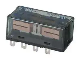


SP2-DC12V
Power Relay, DPDT, 12 VDC, 15 A, SP Series, Socket, Non Latching
- Manufacturer: PANASONIC
- Product type: Power Relays
- SVHC: To Be Advised
- Coil Type: Non Latching
- Coil Voltage: 12VDC
- Product Range: SP Series
- Relay Mounting: Socket
- Coil Resistance: 480ohm
- Contact Current: 15A
- Relay Terminals: Quick Connect
- Contact Material: Silver Tin Oxide
- Contact Voltage VAC: 250V
- Contact Voltage VDC: 30V
- Contact Configuration: DPDT
| Delivery and price | |
|---|---|
| Units per pack | 20 |
| Price | 27.46 € |
| Current stock | 10+ |
| Lead time | 30 days |
## Power Relays ( Over 2 A ) SP RELAYS

## Product Catalog

**==> picture [503 x 408] intentionally omitted <==**

2023.4

## **Power Relays (Over 2 A)**

**SP[RELAYS]**

## **2 Form C 15 A, 4 Form C 10 A, Polarized power relays**

**==> picture [475 x 195] intentionally omitted <==**

**----- Start of picture text -----**<br>
Protective construction:Dust cover type [ FEATURES<br>| High sensitivity: Rated operating power 300 mW<br>Plug-in terminal/PC board terminal<br>25.6 Latching types also available<br>50 Mounts directly on chassis and the mounting board<br>20.5 is also available to enable DIN rail installation<br>3 Terminal sockets are available<br>50 36.8<br>| 20.5<br>(eee? ~<br>4<br>(Unit:mm)<br>**----- End of picture text -----**<br>


~~a~~ **ORDERING INFORMATION (PART NO. : Ordering part number for Japanese market) AR 1** Terminal shape・Operating function Contact arrangement Rated coil voltage(DC) 0:Plug-in type, Single side stable 2 : 2 Form C Part No. 0 1 2 3 8 9 1:Plug-in type, 1 coil latching* 4 : 4 Form C ~~oo~~ Rated coil voltage(V) 6 12 24 48 3 5 2:Plug-in type, 1 coil latching 3:PC board type, Single side stable* 4:PC board type, 1 coil latching* 5:PC board type, 2 coil latching*

*PC board type and 1 coil latching type are manufactured by lot upon receipt of order.

## ~~[~~ **ORDERING INFORMATION (TYPE NO. : Ordering part number for non Japanese market)** ~~I~~

**==> picture [314 x 79] intentionally omitted <==**

**----- Start of picture text -----**<br>
SP<br>Contact arrangement Terminal shape Operating function Rated coil voltage(DC)<br>2:2 Form C Nil:Plug-in type Nil:Single side stable 3, 5, 6, 12, 24, 48V<br>4:4 Form C P :PC board type L :1 coil latching<br>L2:2 coil latching<br>**----- End of picture text -----**<br>


Notes:PC board type and 1 coil latching type are manufactured by lot upon receipt of order.

Panasonic Industry Co., Ltd. Electromechanical Control Business Division industrial.panasonic.com/ac/e/

ASCTB208E   202304

ー 1 ー

Panasonic Industry Co., Ltd. 2023

~~eec~~ Power Relays (Over 2 A ~~reer~~ rere ) reer SP RELAYS c **e** ce

## sy **TYPES**

- "Type No. "is ordering part number for non Japanese market. " Part No. "is ordering part number for Japanese market.

|Contact|Rated coil<br>voltage<br>~~|~~<br>~~a~~|~~|~~<br>~~Singlesitestable~~|~~|~~<br>~~Singlesitestable~~|2coil latching<br>~~|~~|2coil latching<br>~~|~~|Standard packing|Standard packing|
|---|---|---|---|---|---|---|---|
|||~~|~~<br>~~Singlesitestable~~<br>a|~~Singlesitestable ~~<br>es|~~|~~|~~|~~|Inner carton|Outer carton|
|2|3V DC<br>~~a~~|SP2-DC3V<br>a|1028<br>es|SP2-L2-DC3V|1228|20|200|
||V DC<br>~~a ~~|SP2-DC V<br> a|1029<br>es|SP2-L2-DC V|1229|||
||6V DC|SP2-DC6V|1020|SP2-L2-DC6V|1220|||
||12V DC<br>~~RR~~|SP2-DC12V<br>~~RR~~|1021<br>~~RR~~|SP2-L2-DC12V<br>~~RR~~|1221<br>~~RR~~|||
||24V DC<br>~~RR~~<br>~~RR~~|SP2-DC24V<br>~~RR~~<br>~~RR~~|1022<br>~~RR~~<br>~~RR~~|SP2-L2-DC24V<br>~~RR~~<br>~~RR~~|1222<br>~~RR~~<br>~~RR~~|||
||48V DC<br>~~RR~~<br>~~RR~~|SP2-DC48V<br>~~RR~~<br>~~RR~~|1023<br>~~RR~~<br>~~RR~~|SP2-L2-DC48V<br>~~RR~~<br>~~RR~~|1223<br>~~RR~~<br>~~RR~~|||
|4|3V DC<br>~~RR~~<br>~~RR~~|SP4-DC3V<br>~~RR~~<br>~~RR~~|1048<br>~~RR~~<br>~~RR~~|SP4-L2-DC3V<br>~~RR~~<br>~~RR~~|1248<br>~~RR~~<br>~~RR~~|10|100|
||V DC<br>~~RR~~|SP4-DC V<br>~~RR~~|1049<br>~~RR~~|SP4-L2-DC V<br>~~RR~~|1249<br>~~RR~~|||
||6V DC|SP4-DC6V|1040|SP4-L2-DC6V|1240|||
||12V DC<br>~~RR~~|SP4-DC12V<br>~~RR~~|1041<br>~~RR~~|SP4-L2-DC12V<br>~~RR~~|1241<br>~~RR~~|||
||24V DC<br>~~RR~~<br>~~RR~~|SP4-DC24V<br>~~RR~~<br>~~RR~~|1042<br>~~RR~~<br>~~RR~~|SP4-L2-DC24V<br>~~RR~~<br>~~RR~~|1242<br>~~RR~~<br>~~RR~~|||
||48V DC<br>~~RR~~<br>~~RR~~|SP4-DC48V<br>~~RR~~<br>~~RR~~|1043<br>~~RR~~<br>~~RR~~|SP4-L2-DC48V<br>~~RR~~<br>~~RR~~|1243<br>~~RR~~<br>~~RR~~|||


## Ld **RATING**

## **Coil data**

|Rated coil<br>voltage|Operate voltage*<br>(at20°C)|Release voltage*<br>(at20°C)|Rated operating<br>current<br>10<br>20°C)<br>ee ei|Coil resistance<br>10<br>20°C)<br>(t %,at|Ratedoperating power|voltage<br>(at20°C)<br>Max. allowable|
|---|---|---|---|---|---|---|
|3V DC|70<br>rated coil voltage<br>(Initial)|10<br>rated coil voltage<br>(Initial)|100|30|300|coil voltage|
|V DC<br>5|||60 2|83|||
|6V DC||||120|||
|12V DC||||480|||
|24V DC|||12|1 920|||
|48V DC|||6 2|7 700|||


## 2 coil latching

|Rated coil<br>voltage|Set voltage*<br>(at20°C)|Reset voltage*<br>(at20°C)<br>~~p—_}|~~|Rated operating<br>current<br>10<br>20°C)<br>~~p—_}|ff~~|Rated operating<br>current<br>10<br>20°C)<br>~~p—_}|ff~~|Coil resistance<br>10<br>20°C)<br>~~fff~~|Coil resistance<br>10<br>20°C)<br>~~fff~~|~~fT~~|~~fT~~|voltage<br>(at20°C)|
|---|---|---|---|---|---|---|---|---|---|
||||Set coil<br>~~p—_}|~~|Reset coil<br>~~p—_}|ff~~|Set coil<br>~~ff~~|Reset coil<br>~~fff~~|Set coil<br>~~fT~~|Reset coil<br>~~T~~||
|3V DC|70<br>rated coil voltage<br>(Initial)<br>Max.<br>%V<br>of|70<br>rated coil voltage<br>(Initial)<br>~~p—_}|~~<br>Max.<br>%V of|100<br>~~p—_}|~~|100<br>~~p—_}| ff~~|30<br>~~ff~~|30<br>~~ff f~~|300<br>~~fT~~<br>myo|300<br>~~T~~<br>myo|coil voltage<br>450%Vofrated|
|V DC<br>:|||60 2|60 2|83|83||||
|6V DC|||||120|120||||
|12V DC|||||480|480||||
|24V DC|||12|12|1 920|1 920||||
|48V DC|||6 2|6 2|7 680|7 680||||


Panasonic Industry Co., Ltd. Electromechanical Control Business Division industrial.panasonic.com/ac/e/

ASCTB208E   202304

ー 2 ー

Panasonic Industry Co., Ltd. 2023

~~eec~~ Power Relays (Over 2 A ~~reer~~ rere ) reer SP RELAYS c **e** ce

|Item|Item|Specifications|Specifications|
|---|---|---|---|
|Contact data<br>~~P~~|~~P~~|2<br>Max.<br>mQ(by voltagedrop<br>A)|4|
||Contact resistance<br>(initial)<br>~~P~~|30<br>6V DC1<br>Max.<br>mQ(by voltagedrop<br>A)||
||~~P~~<br>Contact material|2<br>2<br>Max.<br>mQ(by voltagedrop<br>A)<br>Stationary contact: Au flashedAgSnO type, Movable contact: AgSnO type||
||Contact rating<br>(resistive)|10<br>30V DC|10<br>10<br>30V DC|
||(resistive)<br>Max. switching power|3<br>300<br>750VA,<br>Ww|2<br>300<br>,500VA,<br>WwW|
||Max. switching voltage ||30V DC (48<br>2<br>|250VAC,<br>V DC: Max.<br>A)||
||Max. switching current ||10<br>|15A(AC),<br>A(DC)|10<br>10<br>A(AC),<br>A(DC)|
||(reference value)*1<br>Min. switching load|100<br>V DC<br>mA5||
|Insulation resistance (initial)||1 000<br>Min.<br>,<br>|MQ (at 500V DC, Measured portion is the same as the case of dielectric strength.)||
|Dielectric<br>strength (initial)|Between open contacts}|1<br>1<br>10<br>,500 Vrms for<br>min (detection current:<br>mA)||
||Between contact sets|3 000<br>1<br>10<br>,<br>Vrms for<br>min (detection current:<br>mA)||
||coil<br>SKF Cela21s]|3 000<br>1<br>10<br>,<br>Vrmsfor<br>min (detection current:<br>mA)||
|characteristics<br>(initial)<br>Time<br>~~PY~~|Operate (Set) time|20<br>Max. 50 ms (Max. 50 ms) at rated coil voltage (at<br>°C, without bounce)||
||Release (Reset) time |<br>~~PY~~|20<br>20<br>|Max.<br>ms (Max. 50 ms) at rated coil voltage (at<br>°C, without bounce, without diode)<br>m/s(half-sineshockpulse:<br>ms,detectiontime:<br>Us)||
|Shock<br>resistance<br>~~PY~~<br>~~Po~~<br>Vibration<br>~~Ps~~|Functional<br>~~PY~~<br>~~Po~~|392<br>2<br>11<br>10<br>m/s(half-sineshockpulse:<br>ms,detectiontime:<br>Us)<br>m/s(half-sineshockpulse:<br>ms)||
||Destructive<br>~~PY~~<br>~~Po~~<br>~~Ps~~|980<br>2<br>6<br>m/s (half-sine shock pulse:<br>ms, detection time:<br>Us)<br>m/s(half-sineshockpulse:<br>ms)<br>55Hz(atdoubleamplitudeofmm,detectiontime:<br>us)||
|resistance<br>~~Po~~<br>Vibration<br>~~Ps~~<br>~~Ps~~<br>Expectedlife~~Ps~~|Functional<br>~~Po~~<br>~~Ps~~<br>~~Ps~~|10to<br>3<br>10<br>m/s (half-sine shock pulse:<br>ms)<br>55Hz(atdoubleamplitudeofmm,detectiontime:<br>us)<br>55Hz(atdoubleamplitudeofmm)||
||Destructive<br>~~Ps~~<br>~~Ps~~<br>~~Ps~~|10to<br>3<br>55Hz (atdouble amplitude of mm, detection time:<br>us)<br>55Hz(atdoubleamplitudeofmm)<br>Min.50<br>ope.(switchingfrequency:at<br>times/min)||
|~~Ps~~<br>Expectedlife~~Ps~~|Mechanical life<br>~~Ps~~<br>~~Ps~~|×106<br>180<br>55Hz (atdouble amplitude of mm)<br>Min.50<br>ope.(switchingfrequency:at<br>times/min)||
|Conditions<br>Expected life ~~Ps~~|transport and storage*2<br>~~Ps~~ <br>(CtrTe iste NIMES(2)|to +60<br>to<br> Min. 50<br>ope. (switching frequency: at<br>times/min)<br>Ambienttemperature: -50<br>°C, Humidity:<br>5<br>85%RH (Avoid icingand condensation)||
|Unit weight||g<br>Approx. 50|g<br>Approx. 65|


## **Expected electrical life**

|2<br>Form C|~~15A250~~|~~15A250 ~~|~~VAC~~|~~Min.~~|100×103|
|---|---|---|---|---|---|
||10|30V DC|V DC|-|100×103|
|4<br>Form C|10|~~A250 ~~|~~V AC~~|~~Min.~~|100×103|
||10|30V DC|V DC|-|100×103|


Panasonic Industry Co., Ltd. Electromechanical Control Business Division industrial.panasonic.com/ac/e/

ASCTB208E   202304

ー 3 ー © Panasonic Industry Co., Ltd. 2023

Power Relays (Over 2 A) SP RELAYS

## [od **REFERENCE DATA**

**==> picture [328 x 521] intentionally omitted <==**

**----- Start of picture text -----**<br>
Tested sample:SP2-24V DC Tested sample:SP4-24V DC<br>Ambient temperature:27 to 29℃<br>50 50<br>40 15A 40<br>10A<br>30 oo 10A 30 iacaaaee<br>Cee CL<br>5A 5A<br>20 tp 20 eT 0A<br>0A<br>See] | }ee<br>10 10<br>0 0<br>19.2 21.6 24.0 26.4 28.8 31.2 33.6 36.0 19.2 21.6 24.0 26.4 28.8 31.2 33.6 36.0<br>Coil applied voltage(%V) Coil applied voltage(%V)<br>2-1.Electrical life test (2 Form C, 15 A 250 V AC Resistive load)<br>Change of operate and release voltage Change of contact resistance<br>N.C.<br>N.O.<br>15 Operate voltage Max. 15<br>Ave. Max.<br>Min.<br>10 Pree) 10 LL al<br>Ave.<br>Max.<br>Ave.<br>5 ines Release voltage Max. 5 See eS Min.Min.<br>Ave.<br>Min.<br>p 0 re | 0 TTL<br>1 2 3 4 5 6 7 8 9 10 1 2 3 4 5 6 7 8 9 10<br>No. of operations(×10 [4] ) No. of operations(×10 [4] )<br>2-2.Electrical life test (4 Form C, 10 A 250 V AC Resistive load)<br>Change of operate and release voltage Change of contact resistance<br>N.C.<br>N.O.<br>50<br>15 Operate voltage Max.<br>Ave.<br>Min. 40<br>10 TOT 30 certetal Max.<br>20<br>5 TLE). Release voltage Poe|<br>Max.Ave. 10 Ave.<br>Min.<br>Min.<br>| 0 [seen | 0 oa e e e<br>1 2 3 4 5 6 7 8 9 10 1 2 3 4 5 6 7 8 9 10<br>No. of operations(×10 [4] ) No. of operations(×10 [4] )<br>(℃) (℃)<br>Temperature rise  Temperature rise<br>)<br>V<br>( Ω)<br>m<br>(Contact resistance<br>Operate and release voltage<br>)<br>V<br>( Ω)<br>m<br>(Contact resistance<br>Operate and release voltage<br>**----- End of picture text -----**<br>


Panasonic Industry Co., Ltd. Electromechanical Control Business Division industrial.panasonic.com/ac/e/

ASCTB208E   202304

ー 4 ー

Panasonic Industry Co., Ltd. 2023

~~eec~~ Power Relays (Over 2 A ~~reer~~ rere ) reer SP RELAYS c **e** ce

## **DIMENSIONS CAD** Po GD The CAD data of the products with a “CAD” mark can be downloaded from our Website.

**==> picture [40 x 8] intentionally omitted <==**

**----- Start of picture text -----**<br>
2 Form C<br>**----- End of picture text -----**<br>


**==> picture [509 x 681] intentionally omitted <==**

**----- Start of picture text -----**<br>
rT] CAD rl CAD PC board pattern<br>External dimensions External dimensions (BOTTOM VIEW)<br>1 50 1 50 10ーφ2.5<br>| : DN | I i" Fe €—_©—_®—_® L<br>fT | Rgi | up| u seSry 10.16 es! 10.16 10.16 10.16<br>Tolerance ±0.1<br>Schematic<br>(BOTTOM VIEW)<br>Single side stable<br>(De-energize)<br>1 5 6 7<br>7eeUg 10.16 10.16 10.16 10.16 FASTON #187 Tr 10.16 10.16 10.16 10.16 +<br>4.75<br>General tolerance ±0.3 2 General tolerance ±0.3<br>Note:Diagram shows the  ! “reset” position when terminals 3 and 4 are energized. Ban8 — - $ 2%<br>Energize terminals 1 and 2 to transfer contacts. 2 8 9 10<br>2 coil latching<br>(Reset)<br>1 5 6 7 3<br>+ +<br>- $ of -<br>2 8 9 10 4<br>| 4 Form C<br>@  Plug-in terminal @ PC board terminal Recommended<br>rl] CAD rl CAD PC board pattern<br>External dimensions External dimensions (BOTTOM VIEW)<br>1 50 1 50 16ーφ2.5<br>10.16 10.16 10.16 10.16<br>| i | i nan<br>Tolerance ±0.1<br>Schematic<br>(BOTTOM VIEW)<br>Single side stable<br>a SS (De-energize)<br>11 12 13<br>TINNY. 10.16 10.16 10.16 10.16 FASTON #187 ry 10.16 10.16 ey 10.16 10.16<br>l! 4.75 | 2 General tolerance ±0.3 1 22 5 6 3 7<br>Note:Diagram shows the “reset” position when terminals 3 and 4 are energized.General tolerance ±0.3 + +7 ¢<br>Energize terminals 1 and 2 to transfer contacts.<br>- $ tt<br>2 8 9 10<br>$ ft<br>14 15 16<br>2 coil latching<br>(Reset)<br>11 12 13<br>+f ¢<br>1 5 6 7 3<br>+ : +<br>- $ 2 % -<br>2 8 9 10 4<br>$ ot<br>14 15 16<br>0.5 0.5<br>10 25.6 15.24 10 25.6 15.24 15.24<br>20.5<br>20.5<br>1.5<br>1.5<br>7.15<br>.5<br>5<br>0.5 0.5<br>7.62<br>7.62 .627 15.24<br>10 36.8 15.24 10 36.8 15.24<br>7.62<br>7.62 .627<br>20.5 20.5<br>1.5 1.5<br>7.15<br>5.5<br>**----- End of picture text -----**<br>


Panasonic Industry Co., Ltd. Electromechanical Control Business Division industrial.panasonic.com/ac/e/

ASCTB208E   202304

ー 5 ー © Panasonic Industry Co., Ltd. 2023

Power Relays (Over 2 A) SP RELAYS ~~reer~~ e erence eee **e**

## **SAFETY STANDARDS** ~~Po~~

## ~~||~~ **UL (Approved) CSA (Approved)**

**==> picture [99 x 119] intentionally omitted <==**

**----- Start of picture text -----**<br>
Contact rating<br>15A 250 VAC<br>10 A 30 V DC<br>1 2 /  HP  125, 250 VAC<br>Contact rating<br>10 A250 V AC<br>10 A 30 V DC<br>1 3 /  HP  125, 250 VAC<br>**----- End of picture text -----**<br>


**==> picture [99 x 119] intentionally omitted <==**

**----- Start of picture text -----**<br>
Contact rating<br>15A250 VAC<br>10 A 30 V DC<br>1 2 /  HP  125, 250 VAC<br>Contact rating<br>10 A250V AC<br>10 A 30 V DC<br>1 3 /  HP  125, 250 VAC<br>**----- End of picture text -----**<br>


## **VDE (Approved)**

**==> picture [99 x 95] intentionally omitted <==**

**----- Start of picture text -----**<br>
Contact rating<br>15A 250 VAC (cosp= 1 0 . )<br>10 A 30 V DC<br>Contact rating<br>10 A250 VAC (cosp= 1 0 . )<br>10 A 30 V DC<br>**----- End of picture text -----**<br>


## **GUIDELINES FOR USAGE**

**For cautions for use, please read “GUIDELINES FOR RELAY USAGE”. https://industrial.panasonic.com/ac/e/control/relay/cautions_use/index.jsp**

Panasonic Industry Co., Ltd. Electromechanical Control Business Division industrial.panasonic.com/ac/e/

ASCTB208E   202304

ー 6 ー

Panasonic Industry Co., Ltd. 2023

~~eec~~ Power Relays (Over 2 A ~~reer~~ rere ) reer SP RELAYS c **e** ce

## **SP RELAYS Terminal sockets**

**==> picture [30 x 8] intentionally omitted <==**

**----- Start of picture text -----**<br>
TYPES<br>**----- End of picture text -----**<br>


**==> picture [489 x 165] intentionally omitted <==**

**----- Start of picture text -----**<br>
Standard packing<br>Inner carton Case<br>SP2 SP2-SF 1922 10<br>SP4 SP4-SF 1942<br>RATING<br>Item Specifications<br>Dielectric strength (initial) Each between terminals: 3 000 , | Vrms for 1 min (detection current: 10 mA)<br>Each between terminals: Min. 1 000 , MQ<br>Insulation resistance (initial)<br>(at  500 V DC, Measured portion is the same as the case of dielectric strength.)<br>Maximum carrying current 15A<br>ae Ambient temperature: -50  to +60°C<br>CSTE Se WE OF) Wee tNEF elt eeTMel ESTEeS Humidity: 5  to  85% RH (Avoid icing and condensation)<br>**----- End of picture text -----**<br>


## **DIMENSIONS CAD** Po QD The CAD data of the products with a “CAD” mark can be downloaded from our Website.

## **SP2 Terminal socket (AR1922)**

## **SP4 Terminal socket (AR1942)**

**==> picture [246 x 321] intentionally omitted <==**

**----- Start of picture text -----**<br>
40.64±0.4<br>20.32±0.4 23±1 20.3±0.6 Mounting pitch<br>Fal-s|-—|-=|-= T 7 o Y<br>|  Ji co )  | __ 304.5±±0.60.4<br>KOOt | } EEO<br>eee —<br>SP relay<br>Screw:M3.5<br>Note:Terminal number marking is on the socket body.<br>Please refer together with the SP relay schematic.<br>52±1 General tolerance ±0.5<br>Mounting hole pattern<br>30±0.2 2ーφ4.5±0.1<br>Notes:<br>1.Mounting screws and the fastening<br>bracket are included in the package.<br>2.Mount the relay with the proper mounting<br>direction  ̶ i.e. with the direction of<br>the    mark on top of the relay case<br>matching the direction of the      mark on the terminal block. ” (The    direction  cf 3)<br>of the terminal block is the upward<br>direction of the relay.)<br>0.4<br>± 0.4<br>±<br>15.24<br>1 6.5<br>±<br>67<br>**----- End of picture text -----**<br>


**==> picture [254 x 207] intentionally omitted <==**

**----- Start of picture text -----**<br>
40.64±0.4<br>20.32±0.4 23±1 Mounting pitch<br>S=/S=|S=lS=1S= D — <<br>| | | a<br>30±0.6<br>4.5±0.3<br>eee ‘ c a ——<br>AOY-_L AY. fry)| _(@)-<br>[e le] 4 :<br>SP relay<br>20.3±0.6<br>11±0.4  Pt 21±0.4 32.8±0.6<br>| r T Screw:M3.5<br>a | 4<br>Note:Terminal number marking is on the socket body.<br>Please refer together with the SP relay schematic.<br>52±1 General tolerance ±0.5<br>0.4<br>0.4 ±<br>± 0.3<br>30.48 ±<br>±1 15.24 ±1 0.6± 6.5<br>97 70.5 40.5<br>**----- End of picture text -----**<br>


Panasonic Industry Co., Ltd. Electromechanical Control Business Division industrial.panasonic.com/ac/e/

ASCTB208E   202304

Panasonic Industry Co., Ltd. 2023

ー 7 ー

~~eec~~ Power Relays (Over 2 A ~~reer~~ rere ) reer SP RELAYS c **e** ce

## Ld **HANDLING**

## **Mounting method of relay**

## **Removing method of relay**

**==> picture [510 x 307] intentionally omitted <==**

**----- Start of picture text -----**<br>
te) eda Sl ra ol aa Brand character 2) Exercise care when removing relays. If greater than necessary<br>ell ep (ell | | } force is applied at the socket hooks, deformation may alter the<br>ett Ga eT ga ed dimensions so that the hook will no longer catch, and other<br>note)Top of the relay case<br>To mount the relay to<br>nell a [a ~ the proper mounting  damage may also occur.<br>ele 1of mie} direction, match the  @  Removing method of fastening bracket<br>direction of the brand  Fastening<br>je] Terminal block ts— el SP relay character string marked on the top of the relay  1) Slidegroove thein Bthe partterminal from the bracket C I)<br>with the arrow direction  socket, while pressing YP minus<br>on the terminal socket. screwdriver<br>SP relay<br>with the tip of a minus a af<br>2) Both ends of the relay are to be 2) Whilescrewdriv th e r.bracket is || qQ)<br>SP relay<br>Terminal block B<br>secured firmly. pressing the C part of  in this position, keep PN)<br>Terminal block<br>on theside bracketwith your to the relayfinger,<br>3) Use the included fastening bracket to firmly secure the relay. and lift up and remove<br>@ Mounting method of fastening bracket from the groove.<br>Fastening<br>1) Insert the A part into the bracket '<br>mounting groove of the<br>terminal socket. yy<br>minus<br>2)  Fit the B part into  screwdriver<br>groove, A SP relay<br>with [the] while pressing [tip] [of] [a] [minus] |inZz [a] NZ<br>Terminal block B<br>screwdriver. S N )<br>**----- End of picture text -----**<br>


Panasonic Industry Co., Ltd. Electromechanical Control Business Division industrial.panasonic.com/ac/e/

ー 8 ー

ASCTB208E   202304

Panasonic Industry Co., Ltd. 2023

~~eec~~ Power Relays (Over 2 A ~~reer~~ rere ) reer SP RELAYS c **e** ce

## **SP RELAYS Mounting board**

Direct chassis mounting possible, and applicable to DIN rail.

## **TYPES**

||Standard packing|Standard packing|
|---|---|---|
||Inner carton|Outer carton|
|1800|10|100|


## **RATING**

|ae<br>Conditions forusage, transportand storage|to +60°C<br>to<br>Ambient temperature: -50<br>Humidity:<br>5<br>85%RH (Avoid icing|and||
|---|---|---|---|
|Shock resistance*|980<br>2<br>m/s|||
|Vibration resistance|10to<br>55 Hz (at double amplitude of|3<br>mm)|mm)|
|*“WhendoingaDINrailinstallation,refertothemounting|mountingmethod3)below:onlydirectionAis588|588m/s|2|


**==> picture [377 x 230] intentionally omitted <==**

**----- Start of picture text -----**<br>
DIMENSIONS CAD<br>Po GD The CAD data of the products with a “CAD” mark can be downloaded from our Website.<br>CAD<br>External dimensions<br>(TY Po 18.4±0.1<br>$F 56.2 i—__§<br>eI n<br>General tolerance ±0.5<br>18.4 25<br>23.2<br>**----- End of picture text -----**<br>


Mounting hole pattern

18.4±0.1 2ーφ3.2

Panasonic Industry Co., Ltd. Electromechanical Control Business Division industrial.panasonic.com/ac/e/

ー 9 ー © Panasonic Industry Co., Ltd. 2023

ASCTB208E   202304

~~eec~~ Power Relays (Over 2 A ~~reer~~ rere ) reer SP RELAYS c **e** ce Ld **HANDLING**

## ~~||~~ **Mounting Method for mounting on DIN rail**

**==> picture [175 x 179] intentionally omitted <==**

**----- Start of picture text -----**<br>
Fit in Mounting<br>board Y slat<br>Press »<br>DIN rail<br>as shown fo l_f o l_f o lfo l _fo} ,<br>ae<br>— |<br>a pe<br>on the opposite side.<br>Fit into mounting grooves.<br>tf To remove therelay, press down<br>A direction E F Co = the mounting slats<br>ey so the claws move<br>to the outside.<br>**----- End of picture text -----**<br>


## —_k—eEeeEEEE **GUIDELINES FOR USAGE**

Panasonic Industry Co., Ltd. Electromechanical Control Business Division industrial.panasonic.com/ac/e/

ー 10 ー © Panasonic Industry Co., Ltd. 2023

ASCTB208E   202304

GUIDELINES FOR POWER, HIGH-CAPACITY DC CUT OFF AND SAFETY RELAYS USAGE

## ■For cautions for use, please read " GUIDELINES FOR RELAY USAGE ". https://industrial.panasonic.com/ac/e/control/relay/cautions_use/index.jsp

## Precautions for Coil Input

## ■Long term current carrying

A circuit that will be carrying a current continuously for long periods without relay switching operation. ( circuits for emergency lamps, alarm devices and error inspection that, for example, revert only during malfunction and output warnings with form B contacts ) Continuous, longterm current to the coil will facilitate deterioration of coil insulation and characteristics due to heating of the coil itself. For circuits such as these, please use a magnetic-hold type latching relay. If you need to use a single stable relay, use a sealed type relay that is not easily affected by ambient conditions and make a failsafe circuit design that considers the possibility of contact failure or disconnection.

## ■DC Coil operating power

Steady state DC current should be applied to the coil. The wave form should be rectangular. If it includes ripple, the ripple factor should be less than 5 %.

However, please check with the actual circuit since the electrical characteristics may vary. The rated coil voltage should be applied to the coil and the set/reset pulse time of latching type relay differs for each relays, please refer to the relay's individual specifications.

## ■Coil connection

When connecting coils of polarized relays, please check coil polarity ( +, - ) at the internal connection diagram ( Schematic ). If any wrong connection is made, it may cause  unexpected malfunction, like abnormal heat, fire and so on, and circuit do not work. Avoid impressing voltages to the set coil and reset coil at the same time.

## ■Maximum allowable voltage and temperature rise

Proper usage requires that the rated coil voltage be impressed on the coil. Note, however, that if a voltage greater than or equal to the maximum continuous voltage is impressed on the coil, the coil may burn or its layers short due to the temperature rise. Furthermore, do not exceed the usable ambient temperature range listed in the catalog.

- ●Operate voltage change due to coil temperature rise In DC relays, after continuous passage of current in the coil, if the current is turned OFF, then immediately turned ON again, due to the temperature rise in the coil, the operate voltage will become somewhat higher. Also, it will be the same as using it in a higher temperature atmosphere. The resistance/temperature relationship for copper wire is about 0.4 % for 1 ℃, and with this ratio the coil resistance increases. That is, in order to operate of the relay, it is necessary that the voltage be higher than the operate voltage and the operate voltage rises in accordance with the increase in the resistance value. However, for some polarized relays, this rate of change is considerably smaller.

Panasonic Industry Co., Ltd. Electromechanical Control Business Division industrial.panasonic.com/ac/e/

> Panasonic Industry Co., Ltd. 2023 ASCTB412E   202301

ー 11 ー

GUIDELINES FOR POWER, HIGH-CAPACITY DC CUT OFF AND SAFETY RELAYS USAGE

## Ambient Environment

■Usage, Transport, and Storage Conditions During usage, storage, or transportation, avoid locations subjected to direct sunlight and maintain normal temperature, humidity and pressure conditions.

- ●Temperature/Humidity/Pressure

- When transporting or storing relays while they are tube packaged, there are cases the temperature may differ from the allowable range. In this case be sure to check the individual specifications.

Also allowable humidity level is influenced by temperature, please check charts shown below and use relays within mentioned conditions. ( Allowable temperature values differ for each relays, please refer to the relay's individual specifications. )

- 1)  Temperature:

   - The tolerance temperature range differs for each relays, please refer to the relay's individual specifications

- 2)  Humidity: 5 to 85 % RH

**==> picture [166 x 142] intentionally omitted <==**

**----- Start of picture text -----**<br>
Humidity (% RH)<br>85<br>Allowa b le range<br>Avoid icing Avoid con-<br>when used at densation when<br>temperatures used at tem-<br>lower than 0°C peratures higher<br>than 0°C<br>5<br>-40 0 85<br>Ambient temperature (℃)<br>**----- End of picture text -----**<br>


- 3)  Pressure: 86 to 106 kPa

- ●Dew condensation

Condensation occurs when the ambient temperature drops suddenly from a high temperature and humidity, or the relay is suddenly transferred from a low ambient temperature to a high temperature and humidity. Condensation causes the failures like insulation deterioration, wire disconnection and rust etc. Panasonic Industry Co., Ltd. does not guarantee the failures caused by condensation.

The heat conduction by the equipment may accelerate the cooling of device itself, and the condensation may occur.

Please conduct product evaluations in the worst condition of the actual usage. ( Special attention should be paid when high temperature heating parts are close to the device. Also please consider the condensation may occur inside of the device. )

## ●Icing

Condensation or other moisture may freeze on relays when the temperature become lower than 0 ℃.This icing causes the sticking of movable portion, the operation delay and the contact conduction failure etc. Panasonic Industry Co., Ltd. does not guarantee the failures caused by the icing.

The heat conduction by the equipment may accelerate the cooling of relay itself and the icing may occur. Please conduct product evaluations in the worst condition of the actual usage.

- ●Low temperature and low humidity

- The plastic becomes brittle if the relay is exposed to a low temperature, low humidity environment for long periods of time.

- ●High temperature and high humidity

Storage for extended periods of time ( including transportation periods ) at high temperature or high humidity levels or in atmospheres with organic gases or sulfide gases may cause a sulfide film or oxide film to form on the surfaces of the contacts and/or it may interfere with the functions. Check out the atmosphere in which the units are to be stored and transported.

## ●Package

In terms of the packing format used, make every effort to keep the effects of moisture, organic gases and sulfide gases to the absolute minimum.

## ●Silicon

When a source of silicone substances ( silicone rubber, silicone oil, silicone coating materials and silicone filling materials etc. ) is used around the relay, the silicone gas ( low molecular siloxane etc. ) may be produced. This silicone gas may penetrate into the inside of the relay. When the relay is kept and used in this condition, silicone compound may adhere to the relay contacts which may cause the contact failure. Do not use any sources of silicone gas around the relay ( Including plastic sealed types ).

- ●NOx Generation

When relay is used in an atmosphere high in humidity to switch a load which easily produces an arc, the NOx created by the arc and the water absorbed from outside the relay combine to produce nitric acid.

This corrodes the internal metal parts and adversely affects operation.

Avoid use at an ambient humidity of 85 % RH or higher ( at 20 ℃ ). If use at high humidity is unavoidable, please contact our sales representative.

Panasonic Industry Co., Ltd. Electromechanical Control Business Division industrial.panasonic.com/ac/e/

ASCTB412E   202301

ー 12 ー

Panasonic Industry Co., Ltd. 2023

GUIDELINES FOR POWER, HIGH-CAPACITY DC CUT OFF AND SAFETY RELAYS USAGE

## Others

## ■Cleaning

- Although the environmentally sealed type relay ( plastic sealed type, etc. ) can be cleaned, avoid immersing the relay into cold liquid ( such as cleaning solvent ) immediately after soldering. Doing so may deteriorate the sealing performance.

- Cleaning with the boiling method is recommended ( The temperature of cleaning liquid should be 40 ℃ or lower ). Avoid ultrasonic cleaning on relays. Use of ultrasonic cleaning may cause breaks in the coil or slight sticking of the contacts due to ultrasonic energy.

Please refer to "the latest product specifications" when designing your product.

- •Requests to customers: https://industrial.panasonic.com/ac/e/salespolicies/

Panasonic Industry Co., Ltd. Electromechanical Control Business Division industrial.panasonic.com/ac/e/

ASCTB412E   202301

ー 13 ー

Panasonic Industry Co., Ltd. 2023

■ Global Sales Network Information: industrial.panasonic.com/ac/e/salesnetwork

Electromechanical Control Business Division 1006, Oaza Kadoma, Kadoma-shi, Osaka 571-8506, Japan industrial.panasonic.com/ac/e/

Specifications are subject to change without notice.

©Panasonic Industry Co., Ltd. 2023

2023.4

������������������
Updated at June 10, 2026
Panasonic Industry is a global leader in the design and manufacture of high-quality electronic components. Renowned for a commitment to continuous innovation, the company provides the essential building blocks that empower modern engineering. From industrial automation to consumer electronics, Panasonic's components are trusted worldwide for their outstanding reliability, efficiency, and long-term performance. The extensive portfolio is anchored by a massive selection of passive components, featuring an industry-leading range of aluminium electrolytic, film, and polymer capacitors. Alongside these advanced capacitance solutions, engineers rely on Panasonic's robust power inductors and a highly versatile array of electromechanical devices, including solid-state, power, and signal relays engineered to excel in demanding environments. Beyond core passives and switching solutions, the offering encompasses critical circuit protection devices such as TVS varistors and NTC thermistors, as well as sophisticated thermal management materials. Panasonic also delivers precision light and motion sensors, highly reliable batteries, and advanced Bluetooth and WLAN connectivity modules, providing a comprehensive ecosystem of components to support next-generation technological design.
About Novapart
Novapart is a B2B electronic component broker specialising in stock shortages and cost reduction. We source hard-to-find parts and identify compliant alternatives across a catalogue of 540,000+ components from 500+ manufacturers.
Learn more →Stock Shortage Specialist
When a component is unavailable, discontinued or has an unacceptable lead time, we tap into our network of vetted European and Asian distributors to source what you need — without compromising on quality or traceability.
Request a quote →Compliant Alternatives
We identify pin-to-pin, electrically equivalent substitutes that meet the same certifications (RoHS, AEC-Q100, REACH) as your original specification — validated against datasheets, not just part numbers. Often at a lower cost.
BOM Analysis service →