
Image not available
Illustrative purposes only

SP 8-100
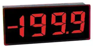
Digital Panel Meter, DC Millivolts, 3-1/2Digits, 0-200mV, 14.2mm Digit Height, 5.25V
⚠️ Reference pricing provided. In case of supply shortages, we will connect you with our trusted procurement partners to ensure your project's continuity.
- Manufacturer: LASCAR
- Product type: Digital Panel Meters
- No. of Digits / Alpha:3-1/2; Meter Function:DC Voltage; Meter Range:0mV to 200mV; Digit Height:14.2mm; Panel Cutout Height:23.6mm; Panel Cutout Width:55.2mm; Supply Voltage Min:4.
- SVHC: No SVHC (07-Nov-2024)
- Meter Range: 0mV to 200mV
- Digit Height: 14.2mm
- Product Range: -
- Meter Function: DC Millivolts
- Panel Cutout Width: 55.2mm
- Supply Voltage Max: 5.25V
- Supply Voltage Min: 4.75V
- Panel Cutout Height: 23.6mm
- No. of Digits / Alpha: 3-1/2
- Operating Temperature Max: 50°C
- Operating Temperature Min: 0°C
| Delivery and price | |
|---|---|
| Units per pack | 10 |
| Price | 59.44 € |
| Current stock | 10+ |
| Lead time | 30 days |
Datasheet

SP 8-100

3½ Digit LED Voltmeter Module

The SP 8-100 features a 200mV d.c. measurement range with auto-zero and auto-polarity. Decimal points are user selectable. The SP 8-100 features a negative rail generator which enables the meter to measure a signal referenced to its own power supply 0V. The bright red LED display ensures excellent readability under low light conditions. The module is easily fitted into the panel, using the fixing clip provided. The module's low cost means it will suit high and low volume applications. The design of the panel meter's housing and seal ensures splash proofing in many applications.

## **FEATURES**

- 14.2mm (0.56") Digit Height

- 200mV d.c. Full Scale Reading

- 50mA @ +5V d.c. Power Supply

- Auto-zero and Auto-polarity

- • Programmable Decimal Points • Bright Red LED Display

- Splash Proof

## **TYPICAL APPLICATIONS**

- Precision Instrumentation Systems

- Power Supply Monitoring

- Test Boxes

**ORDERING INFORMATION** Stock Number Standard Meter **SP 8-100** Po

- Panel-Mount Indication

## **ELECTRICAL SPECIFICATIONS**

|**Specification**|**Min.**|**Typ.**|**Max.**|**Unit**|
|---|---|---|---|---|
|Accuracy (overall error) *||0.1||%(±1 count)|
|Linearity|||±1|count|
|Sample rate||2.5||samples/sec|
|Operatingtemperature range|0||50|°C|
|Warm-uptime||10||minute|
|Temperature stability||150||ppm/°C|
|Supplyvoltage|4.75|5|5.25|V|
|Supplycurrent||50|90|mA|
|Input leakage current (Vin = 0V)||1|10|pA|


* To ensure maximum accuracy, re-calibrate periodically.

## **SAFETY**

To comply with the Low Voltage Directive (LVD 93/68/EEC), input voltages to the module’s pins must not exceed 60Vdc. The user must ensure that the incorporation of the panel meter into the user’s equipment conforms to the relevant sections of BS EN 61010 (Safety Requirements for Electrical Equipment for Measuring, Control and Laboratory Use).

LASCAR ELECTRONICS LTD. LASCAR ELECTRONICS INC. LASCAR ELECTRONICS (HK) LTD. MODULE HOUSE, 4258 WEST 12th STREET, 8th FLOOR, CHINA AEROSPACE CENTRE, WHITEPARISH, ERIE, 143 HOI BUN ROAD, WILTSHIRE SP5 2SJ, PA 16505, KWUN TONG, KOWLOON, UK USA HONG KONG TEL: +44 (1794) 884567 TEL: +1 (814) 835 0621 TEL: +852 2389 6502 FAX: +44 (1794) 884616 FAX: +1 (814) 838 8141 FAX: +852 2389 6535 E-mail: sales@lascar.co.uk E-mail: us-sales@lascarelectronics.com E- mail: saleshk@lascar.com.hk _**Specifications liable to change without prior warning**_ **SP 8-100 Issue 7 06/2010 S.L. Applies to SP 8-100/1** Page 2 of 4 www.lascarelectronics.com No: 756 - Page 1 of 4 Cusck

SP 8-100

3½ Digit LED Voltmeter Module

## **DIMENSIONS**

All dimensions in mm (inches)

**==> picture [391 x 117] intentionally omitted <==**

**----- Start of picture text -----**<br>
6.4 a b c<br>(0.25)<br>PIN 1<br>6.6 a. 1.0 (0.04)<br>(0.26) b. 14.2 (0.56)<br>CAL<br>c. 6.0 (0.24)<br>d d. 2.54 (0.10)<br>45.7 (1.80)<br>53.2 (2.09)<br>55.2 (2.17)<br>(0.93) (0.85)<br>23.6 21.6<br>**----- End of picture text -----**<br>


## **PANEL FITTING**

**==> picture [483 x 461] intentionally omitted <==**

**----- Start of picture text -----**<br>
Panel<br>Module Seal Fixing Clip<br>1 2 3 4<br>FUNCTIONAL BLOCK DIAGRAM PIN CONFIGURATION (rear view)<br>V+<br>REF BG/ it<br>HOLD<br>12 1 2 3 4 5 1<br>COM INL V+<br>INH T/DE<br>CAL COM Rb Ra 0V<br>RO o t he ° == CAL Z= oo m °<br>REF BG/HOLD La DP3<br>RI T/DE RO DP2<br>RI DP1<br>INH 7 6<br>A/D<br>+_ _ 1 8 ° °<br>INL<br>0V DP1 2 3<br>Specifications liable to change without prior warning SP 8-100 Issue 7 06/2010 S.L. Applies to SP 8-100/1<br>Page 2 of 4<br>www.lascarelectronics.com No: 756 - Page 2 of 4<br>@uscaRes |)<br>**----- End of picture text -----**<br>


SP 8-100

3½ Digit LED Voltmeter Module

## **CIRCUIT DIAGRAM**

**==> picture [401 x 267] intentionally omitted <==**

**----- Start of picture text -----**<br>
L5 L4<br>1<br>La<br>11 L__}RA {__}Re Wineot RIa 180K 29g INT veon powpeap ig]a8he} POL COMMONANODE<br>RB ce ee24 ke4/2 cd| a<br>zene 33] INHI Diet Ie|OL<br>12 , waxina Et [EEF<br>10 PO34 comINLO i:2| 1k5<br>co Sc REF+ 5abe ops 6<br>J [|<br>7 wTeet 35Scae Re 462bee k2_——lea|—«*E (1-999) i 1k5<br>4 REF LO 82AS ps SSS—~ AZ2 DP2 {_t 5<br>3 ©ms tus 35)49 NDCAPS“AP aBFeh |dB ort — 1k5 4<br>AL AL<br>2k oe cc 6 3 (199-39<br>R V- _OGND7<br>8k2 8069 + L3 2<br>8 | ¥ 1.5uF T | <q {|<br>BAV70 560R<br>10k<br>100k<br>L1<br>L2<br>9<br>**----- End of picture text -----**<br>


## **PIN FUNCTIONS**

1. V+ Positive power supply to the meter. 2. T Display Test. Connect to V+ to display all LED segments, except for decimal points. Do not connect T to V+ for more than 10 seconds.

DE When solder links L3 and L5 are cut and solder link L4 is closed, the LED display is blanked. Connect DE to V+ to activate the LED display. This feature is useful for low power applications. The Display Test function is then no longer available.

3. 0V 0V power supply connection to the meter. 4. DP3 Connect to 0V to display DP3 (199.9). 5. DP2 Connect to 0V to display DP2 (19.99). 6. DP1 Connect to 0V to display DP1 (1.999). 7. R I Reference voltage input for the meter's A/D converter. 8. RO Precision reference voltage output. Connect to RI for normal operation. 9. REF BG Output voltage from bandgap reference, +1.23V with respect to COM, must not be allowed to supply more than 15 A to external loads.

HOLD When solder link L1 is cut and solder link L2 is closed, then connecting HOLD to V+ will freeze the current reading on the display. After disconnecting HOLD from V+, and allowing time for the reading to stabilise, the display will show the currently measured value.

10. COM Ground for analogue section of A/D converter. It is actively held at 3.05V (nom) below V+ and must not be allowed to sink excessive current (>100 A) by, for instance, connecting to a higher voltage.

11. INH Positive measuring input. 12. INL Negative measuring input.

## Note:

A negative supply is generated internally and mirrors the positive supply. For example: if V+ is +5V, then the internally generated V- is -5V. When measuring with the input referenced to the same supply rail as that of the panel meter, then the limitations on the input range are (V- + 1.5V) to (V+ - 1.5V).

_**Specifications liable to change without prior warning**_ **SP 8-100 Issue 7 06/2010 S.L. Applies to SP 8-100/1**

SP 8-100

3½ Digit LED Voltmeter Module

## **SCALING**

Two resistors Ra and Rb may be added to the SP 8-100

|**SCALING**<br>Two resistors Ra and Rb may||||||||||||||||||||||
|---|---|---|---|---|---|---|---|---|---|---|---|---|---|---|---|---|---|---|---|---|---|
|Two resistors Ra and Rb may|||||**FSR**||**Ra**||**Rb**|||||La||||||||
|be added to the SP 8-100|||||2V||910k**||100k|||||||||||||
|to alter the full scale reading|||Voltage||20V||1M**||10k|+||||||||||11|INH|
|(FSR) of the meter - see|||Vin||200V||1M**||1k||||Ra|||||||||
|table. The meter will have|||||2000V*||1M**||100R|Vin or|I|in||||Rb|||||SP 8-100|
|to be re-calibrated by<br>adjusting the calibration|||in<br>I<br>Current||200 A<br>2mA<br>20mA||0R<br>0R<br>0R||1k<br>100R<br>10R|-||||||||||12|INL|
|potentiometer (CAL) on|||||200mA||0R||1R|||||||||||||
|The module.|*||Ensure that Ra is rated for high voltage use.|Ensure that Ra is rated for high voltage use.||||||||||||||||||
||** Ensure solder link La is cut.|||||||||||||||||||||


## **APPLICATIONS**

Do not connect more than one meter to the same power supply if the meters cannot use the same signal ground.Takinganyinputbeyondthepowersupplyrailswilldamagethemeter.

**==> picture [461 x 397] intentionally omitted <==**

**----- Start of picture text -----**<br>
V+ V+ V+<br>1 1 Set Zero 1<br>V+ V+ 220k V+<br>11 11<br>±200mV+- 12 INHINL RORI 87 ±200mV+- 12 INHINL RORI 87 4-20mA I+ 5k 1012 INLCOM RORI 87<br>current loop R<br>10 COM I- 11 INH<br>0V 0V 0V<br>3 3 3<br>oo 0V 0V 5 0V<br>Measuring an input voltage referenced Measuring a single ended input Measuring a 4-20mA loop current.<br>to a floating supply, i.e. the input voltage referenced to supply, i.e. the R= Reading at 20mA<br>voltage and the meter's power supply input voltage and the meter's power 160<br>are isolated from each other. supply share the same 0V rail.<br>The meter's power supply must be<br>isolated from the 4-20mA current<br>loop.<br>I<br>+5V<br>7805 1 Ra=1M 1 V+<br>V+ V+<br>V 220nF 10uF470nF 1087 COMRORI INH 11S1 VA Load RL R 1211 INHINL RORI 87<br>INL 12 Rb=1k 10 COM<br>R = 0.2<br>0V 0V<br>iol 3 Rs = IFSR ) 3 0V<br>Shunt<br>Measuring supply voltage and current to a load. Measuring current.<br>The meter's supply is isolated<br>S selects between voltage and current measurement. from the current being measured.<br>Ra and Rb shown scaled for 200V Rs = 200mV (e.g. 0.1 / 400mW for 2A full scale)<br>I<br>Display DP1, DP2 or DP3, by connecting to 0V, as required.<br>**----- End of picture text -----**<br>


_**Specifications liable to change without prior warning**_ **SP 8-100 Issue 7 06/2010**

**S.L. Applies to SP 8-100/1**
Updated at June 9, 2026
About Novapart
Novapart is a B2B electronic component broker specialising in stock shortages and cost reduction. We source hard-to-find parts and identify compliant alternatives across a catalogue of 410,000+ components from 500+ manufacturers.
Learn more →Stock Shortage Specialist
When a component is unavailable, discontinued or has an unacceptable lead time, we tap into our network of vetted European and Asian distributors to source what you need — without compromising on quality or traceability.
Request a quote →Compliant Alternatives
We identify pin-to-pin, electrically equivalent substitutes that meet the same certifications (RoHS, AEC-Q100, REACH) as your original specification — validated against datasheets, not just part numbers. Often at a lower cost.
BOM Analysis service →