
Image not available
Illustrative purposes only

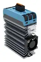
SMQR9623410-WFF05
Solid State Relay, 4 Leg, IP20, 18 A, 600 VAC, DIN Rail, Screw, Zero Crossing
⚠️ Reference pricing provided. In case of supply shortages, we will connect you with our trusted procurement partners to ensure your project's continuity.
- Manufacturer: CELDUC
- Product type:
- SVHC: No SVHC (27-Jun-2024)
- Load Current: 18A
- Product Range: SMQR Series
- Relay Mounting: DIN Rail
- Switching Mode: Zero Crossing
- Relay Terminals: Screw
- Control Voltage Max: 30VDC
- Control Voltage Min: 10VDC
- Contact Configuration: -
- Operating Voltage Max: 600VAC
- Operating Voltage Min: 24VAC
| Delivery and price | |
|---|---|
| Units per pack | 1 |
| Price | 341.11 € |
| Current stock | 10+ |
| Lead time | 30 days |
Datasheet

~~S/SMQR9623410-WFF05/A/14/12/2023~~

page 1 / 6F/GB

## ~~**sightpac**~~ **[®]**

## **Relais statique quad de puissance raccordement "push-in" Four-legs Power Solid State Relay with "push-in" terminals**

- →  Relais statique Quad synchrone spécialement adapté aux charges résistives. Four-legs Zero Cross Solid State Relay especially designed for AC-1 resistive loads.

- →  Sortie 24 à 600VAC 4x25A. 4x18A @40°C suivant courbe page 3. Output : 24 to 600VAC 4x25A. 4x18A @40°C in air calm according thermal curve page 3.

## **SMQR9623410 -WFF05 Output : 24-600VAC 4x18A Input : 10-30VDC**

- →  Protection en tension sur la sortie (transil). Over-Voltage protection on output (transil).

- →  Entrée quadruple avec LED de visualisation de couleur verte sur chaque entrée. 4 inputs with green LED visualization for each input.

- **→** Connecteurs de puissance ressort type "push-in" doublés (6mm² max). Double "push-in" spring power terminals (max. 6mm²).

- →  Connecteur de commande ressort débrochable type "push-in" 5 pôles (2,5mm² max). 5 poles "push-in" pluggable spring control terminal (max. 2.5mm²).

→ Construit en conformité aux normes IEC/EN60947-4-3 ; IEC 60335-1/ VDE0700-1 ; IEC 62314. Designed in conformity with IEC/ EN60947-4-3 ; IEC 60335-1/ VDE0700-1 ; IEC 62314.

## Dimensions (mm)

**==> picture [364 x 215] intentionally omitted <==**

**----- Start of picture text -----**<br>
1<br>: ,<br>a2-<br>.an 5 " = osfs a<br>=| p—— ——| 2 o— b1+ yA<br>a Ie “<br>C2 A2<br>- Sn) =<br>C1/ A1/<br>i D1 | Pett B1 4<br>IF c<br>—— 2<br>= D2 @ B2 *<br>INPUT<br>5<br>| 25,4 | com L nee<br>3 -<br>d1+ c1+ com - b1 + a1 +<br>**----- End of picture text -----**<br>


## _**Proud to serve you**_

**==> picture [237 x 75] intentionally omitted <==**

**----- Start of picture text -----**<br>
celduc [®]<br>r     e     l     a     i     s<br>**----- End of picture text -----**<br>


All technical caracteristics are subject to change without previous notice. Caractéristiques sujettes à modifications sans préavis.

~~S/SMQR9623410-WFF05/A/14/12/2023~~

## ~~**sightpac**~~ **[®]**

## **Caractéristiques d'entrée / Control characteristics (at 25°C)**

page 2 / 6F/GB

|Par voie /for each input<br>DC<br>Fig.1 : Input Ic = f( Uc)|Par voie /for each input<br>DC<br>Fig.1 : Input Ic = f( Uc)|||||
|---|---|---|---|---|---|
|Paramètre /Parameter<br>Symbol<br>Min<br>Typ<br>Max<br>Unit<br>Tension de commande /Control voltage<br>Courant de commande /Control current(@Uc)<br>Tension de non fonctionnement /Release voltage<br>LED d'entrée / Input LED<br>Uc<br>Ic<br>10<br>6<br>Uc off<br>2<br>12<br>8<br>30<br>24<br>verte /green<br>V<br>mA<br>V<br>Tension inverse /Reverse voltage<br>Urv<br>no<br>0<br>2<br>4<br>6<br>8<br>10<br>12<br>14<br>16<br>18<br>20<br>22<br>24<br>~~TT TT tt tt tt ttt te~~<br>~~TTT TT tt tt tt~~<br>~~ey |~~<br>~~EEREEEEEE EEE~~<br>z<br>~~ft tt~~<br>| ~~tt tT~~<br>| ~~meme~~<br>E<br>~~a~~<br>~~Ane~~<br>8<br>~~ERE EEEEE~~<br>~~anne~~<br>~~Cee EE EEEEEE~~<br>~~Panne~~||||||
|Immunité /Input immunity: EN61000-4-4<br>Immunité /Input immunity: EN61000-4-5<br>2kV (criteria B)<br>2KV (cirteria B)<br>0<br>2<br>4<br>6<br>8 10 12 14 16 18 20 22 24 26 28 30<br>Uc (V)||||||
|**Caractéristiques de sortie/ Output characteristics(at 25°C)**<br>par voie/for each output||||||
|Paramètre /Parameter<br>Conditions<br>Symbol<br>Min<br>Typ.<br>Max<br>Unit<br>~~GO~~||||||
|Plage de tension utilisation /Operatingvoltage range<br>Ue<br>24<br>400<br>600<br>V rms<br>Tension de crête (autoamorçage) /<br>Peak voltage(self turn ON)<br>Up<br>1200 (1046)<br>V<br>~~GG~~<br>~~QO~~||||||
|Niveau de synchronisme /Zero cross level<br>Tension minimum amorçage/ Latchingvoltage<br>Ie typ<br>Usync<br>Ua<br>35<br>10<br>V<br>V<br>Courant nominal /nominal current (AC-1) @40°C<br>Courant surcharge/ Non repetitive overload current<br>Chute directe à l'étatpassant /On state voltage drop<br>Tension seuil à l'étatpassant /On state Threshold voltage<br>Voir/SeeFig. 2<br>tp=20ms<br>Ie AC-1<br>Itsm<br>(Ie = nominal current)<br>@25°C<br>V<br>Vto<br>Résistance dynamique /On  state dynamic resistance<br>Puissance dissipée (max) par phase /<br>Outputpower dissipation(max value) per leg<br>rt<br>Pd<br>240<br>18<br>0,85+0,020xIe<br>A rms<br>A<br>0,85<br>V<br>V<br>0,765xIe + 0,020xIe²<br>20<br>mΩ<br>W<br>~~GG~~<br>~~QO~~<br>~~GG~~<br>~~QO~~<br>~~GG~~<br>~~QO~~<br>~~GO~~<br>~~QO~~<br>~~QO~~<br>~~GG~~<br>~~QO~~<br>~~QC~~<br>~~QO~~||||||
|Résistance thermique jonction/semelle<br>Thermal resistance betweenjunction to case<br>Rthj/c<br>1.7<br>K/W||||||
|Courant de fuite à l'état bloqué/ Off state leakage current<br>@Ue typ, 50Hz<br>Ilk<br>1<br>mA<br>Courant minimum de charge/ Minimum load current<br>Temps de fermeture/ Turn on time<br>Temps d'ouverture /Turn off time<br>Fréquence utilisation/ Operatingfrequencyrange<br>@Ue typ, 50Hz<br>Iemin<br>ton max<br>@Ue typ, 50Hz<br>F mains<br>toff max<br>f<br>dv/dt à l'état bloqué /Off state dv/dt<br>di/dt max /Maximum di/dt non repetitive<br>I²t(<10ms)<br>Immunité /Conducted immunitylevel<br>dv/dt<br>di/dt<br>IEC/EN61000-4-4(bursts)<br>I²t<br>5<br>0,1<br>50-60<br>10<br>mA<br>ms<br>10<br>200<br>ms<br>Hz<br>500<br>380<br>2kV criterion B<br>50<br>V/µs<br>A/µs<br>A²s<br>Immunité /Conducted immunitylevel<br>Protection court-circuit /Short circuitprotection<br>IEC/EN61000-4-5(surge)<br>Iq=100kA(voir/see page 6)<br>Type 2<br>2kV criterion B<br>IEC Fuse MERSENgRC 25A 14x51<br>~~GG~~<br>~~QO~~<br>~~GG~~<br>~~QO~~<br>~~GG~~<br>~~QO~~<br>~~GO~~<br>~~QO~~<br>~~QO~~<br>~~GG~~<br>~~QO~~<br>~~GG~~<br>~~QO~~<br>~~QC~~<br>~~QO~~<br>~~a~~<br>~~G~~<br>~~QO~~<br>~~QO~~<br>~~QD~~||||||
|**Caractéristiquesgénérales /General characteristics(at 25°C)**||||||
|Isolement entrée/sortie -Input to output insulation<br>Ui<br>4000<br>VRMS<br>~~a~~||||||
|Isolation sortie/ semelle -Output to case insulation<br>Ui<br>2500<br>VRMS<br>~~a~~||||||
|Résistance Isolement /Insulation resistance<br>Ri<br>1000(@500VDC)<br>MΩ<br>~~GG~~||||||
|Tenue aux tensions de chocs /Rated impulse voltage<br>Degré deprotection /Protection level/  CEI529<br>Degré depollution /Pollution degree<br>Uimp<br>-<br>4000<br>IP20<br>3<br>V<br>Vibrations /<br>Vibration withstand10-150HzaccordingtoIEC60068-2-6<br>double<br>amplitude<br>1,5<br>mm<br>~~a (~~<br>~~**(**~~<br>~~a (~~<br>~~OO~~<br>~~QO~~||||||
|Tenue aux chocs /Shocks withstand accordingtoIEC60068-2-6<br>Tenue chocs et vibrations/Vibration and schocks accordingEN61373<br>Température de fonctionnement /Ambient temperature(no icing, no codensation)<br>11ms<br>-<br>Température de stockage /Storage temperature(no icing,no condensation)<br>Humidité relative /Ambient humidity<br>Poids /Weight<br>Conformité CE /CE conformity<br>HR<br>> 30 .... 50<br>-40 /+100<br>g<br>°C<br>-40/+125<br>40 to 85<br>130<br>EN60947-4-3(IEC947-4-3)<br>°C<br>%<br>g<br>~~GG~~<br>~~CO~~<br>~~GO~~<br>~~GO~~<br>~~QO~~<br>~~a (~~<br>~~(~~<br>~~a (~~<br>~~(~~<br>~~**a**~~<br>~~(~~||||||
|Plastique du boitier /HousingMaterial<br>Semelle /Baseplate<br>PA 6 UL94VO<br>Aluminium<br>~~a~~<br>~~QO~~<br>~~GO~~||||||
||**r     e     l     a     i     s**<br>~~**www.celduc.com**~~<br>**celduc**<br>**®**<br>ofo0~~C~~|||||
||**5, Rue Ampère BP30004     42290 SORBIERS - FRANCE**<br>**Fax +33 (0) 4 77 53 85 51            Service Commercial France Tél. : +33 (0) 4 77 53 90 20**<br>Qualité|||||
||**Sales Dept.For Europe Tel. : +33 (0) 4 77 53 90 21    Sales Dept. Asia : Tél. +33 (0) 4 77 53 90 19**|||||


~~**sightpac**~~ **[®]**

~~S/SMQR9623410-WFF05/A/14/12/2023~~

page 3 / 6F/GB

**Fig. 2 Thermal curves and heatsink choice / Courbes thermiques & Choix dissipateur thermique** :

WFF051210 = 0,5K/W en montage vertical en air calme / 0.5K/W in vertical mounting in air calm. Vérifier que la température du dissipateur n'excède pas 90/100°C. Check if the heatsink temperature does not exceed 90/100°C.

Nouvelle gamme de dissipateurs **celduc** / New range of **celduc** heatsinks : nous contacter / consult us

**Fig.3 : Courants de surcharges / Overload currents**

1 - No repetitive Itsm (1) is given without voltage reapplied . This curve is used to define the protection (fuses).

1 - Itsm non répétitif (1) sans tension réappliquée est donné pour la détermination des protections 1 (fusibles). 2 - Repetitive Itsm (2)  is given for inrush current with initial Tj = 70°C. In normal operation, this curve E 10 es 2 musn't be exceeded. = Repetitive Caution, frequent over load currents will decrease 50 the life expectancy of the SSR.

- 2 -Itsm répétitif (2) est donné pour des surcharges de courant (Tj initiale=70°C). Attention : la répétition, en usage normal, de ces surcharges de courant diminue la durée de vie du relais.

→ Attention ! les relais à semi-conducteurs ne procurent pas d'isolation galvanique entre le réseau et la charge. Ils doivent être utilisés associés à un disjoncteur avec propriété de sectionnement ou similaire, afin d'assurer un sectionnement fiable en amont de la ligne dans l'hypothèse d'une défaillance et pour tous les cas où le relais doit être isolé du réseau (maintenance; non utilisation sur une longue durée...).

Sous réserve d'installation, d'entretien et d'utilisation conformes à sa destination, à la réglementation, aux normes en vigueur, aux instructions du constructeur et aux règles de l'art.

→ Warning !  semiconductor relays don't provide any galvanic insulation between the load and the mains. Always use in conjunction with an adapted circuit breaker with insulation feature  or a similar device in order to  ensure a reliable insulation in the event of wrong function and when the relay must be insulated from the mains (maintenance ; if not used for a long duration ...).

It is important that the solid state relay is subject to correct installation, maintenance and use conforming to its intended regulations and standards, to the supplier's instructions and to accepted rules of art.

**® celduc**

~~**www.celduc.com**~~

**r     e     l     a     i     s**

**5, Rue Ampère BP30004     42290 SORBIERS - FRANCE Fax +33 (0) 4 77 53 85 51            Service Commercial France Tél. : +33 (0) 4 77 53 90 20 Sales Dept.For Europe Tel. : +33 (0) 4 77 53 90 21    Sales Dept. Asia : Tél. +33 (0) 4 77 53 90 19**

~~**sightpac**~~ **[®]**

~~S/SMQR9623410-WFF05/A/14/12/2023~~

page 4 / 6F/GB

## **Raccordement / Connections**

## **sightpac[®]**

## **Raccordement de puissance /  Power wiring**

## **Raccordement "Push-In"**

Raccordement simple, sans contrainte physique et sans outil Câblage rapide et sans effort, même dans les espaces exigus Entrée de fil spacieuse et conique pour faciliter l‘introduction des conducteurs Câblage 100% sécurisé, 70% plus rapide ==> Gain de temps Conducteurs rigides ou souples avec embout ==> Push-In Conducteurs souples :   1- Ouvrir avec un simple tournevis

3- Enlever le tournevis

## **"Push-In" Connection**

Simple connection without physical constraint and without tools Fast and effortless wiring, even in tight spaces Spacious and conical wire entry ==> Easy the introduction of conductors Wiring 100% secure, 70% faster ==> Time saving Rigid or flexible conductors with ferrules ==> Just Push-In Flexible conductors :     1- Open with a screwdriver

3- Remove the screwdriver

|**Caractéristiques de raccordement/ Connection specifications**|||
|---|---|---|
|Section de conducteur rigide/ Solid Wire dimension|min. 0,2 mm²|max. 6 mm²|
|Section de conducteur souple /Fine Stranded dimension|min. 0,2 mm²|max. 4 mm²|
|Section de conducteur souple avec embout sans cône d'entrée isolant/ With standard ferrule|min. 0,25 mm²|max. 2,5 mm²|
|Section de conducteur souple avec embout et cône d'entrée isolant/ With reinforced insulation ferrule|min. 0,25 mm²|max. 2,5 mm²|
|Section du conducteur AWG/ AWG wiring|min. 24|max. 10|
|Longueur à dénuder /Stripping length|8 mm||
|Courant de charge maximal par point /Maximum current per point|41 A||
|Nombre de pôles par connecteur/ Number of points per connector|2||


® **celduc** ~~**www.celduc.com**~~ **r     e     l     a     i     s 5, Rue Ampère BP30004     42290 SORBIERS - FRANCE** ~~a~~ **Fax +33 (0) 4 77 53 85 51            Service Commercial France Tél. : +33 (0) 4 77 53 90 20 Sales Dept.For Europe Tel. : +33 (0) 4 77 53 90 21    Sales Dept. Asia : Tél. +33 (0) 4 77 53 90 19**

~~**sightpac**~~ **[®]**

~~S/SMQR9623410-WFF05/A/14/12/2023~~

page 5 / 6F/GB

## **Raccordement de commande par connecteurs débrochables / Control connections by pluggable connector**

## **sightpac[®]**

## **Raccordement de commande /  Control wiring**

## **Raccordement "Push-In"**

Raccordement simple, sans contrainte physique et sans outil Câblage rapide et sans effort, même dans les espaces exigus Entrée de fil spacieuse et conique pour faciliter l‘introduction des conducteurs Câblage 100% sécurisé, 70% plus rapide ==> Gain de temps Conducteurs rigides ou souples avec embout ==> Push-In Conducteurs souples :      1- Ouvrir avec un simple tournevis

2- Insérer le conducteur

3- Enlever le tournevis

## **"Push-In" Connection**

Simple connection without physical constraint and without tools Fast and effortless wiring, even in tight spaces Spacious and conical wire entry ==> Easy the introduction of conductors Wiring 100% secure, 70% faster ==> Time saving Rigid or flexible conductors with ferrules ==> Just Push-In Flexible conductors :       1- Open with a screwdriver

2- Insert the conductor 3 - Remove the screwdriver :aaa‘ ~~1~~ **Caractéristiques de raccordement** S ~~ection de conducteur rigide / Solid Wire dimension~~ **/ Connection specifications** :1 min. 0,2 mm² a :1 max. 2,5 mm² :' Section de conducteur souple / Fine Stranded dimension min. 0,2 mm² max. 2,5 mm² ~~a~~ ‘ ~~1~~ Section de conducteur souple avec embout sans cône d'entrée isolant / With standard ferrule 1 min. 0,25 mm² a 1 max. 2,5 mm² ' 4‘ Section de conducteur souple avec embout et cône d'entrée isolant / With reinforced insulation ferrule **\** min. 0,25 mm² 1 max. 2,5 mm² . a‘1 Section du conducteur AWG ee / AWG wiring ee ee 1 ee min. 24 1 max. 14 ' \a Longueur à dénuder / Stripping length 10 mm **‘** Courant de charge maximal par point / Maximum current per point \ 24 A 1 . a Nombre de pôles par connecteur / Number of points per connector 5

® **celduc** ~~**www.celduc.com**~~ **r     e     l     a     i     s** ~~™~~

**5, Rue Ampère BP30004     42290 SORBIERS - FRANCE Fax +33 (0) 4 77 53 85 51            Service Commercial France Tél. : +33 (0) 4 77 53 90 20 Sales Dept.For Europe Tel. : +33 (0) 4 77 53 90 21    Sales Dept. Asia : Tél. +33 (0) 4 77 53 90 19**

~~S/SMQR9623410-WFF05/A/14/12/2023~~

## ~~**sightpac**~~ **[®]**

page 6 / 6F/GB

## **Montage / Mounting :**

- −> Les relais statiques de la gamme sightpac[®] doivent être montés sur dissipateur thermique. Une gamme étendue de dissipateurs est disponible. Voir exemples ci dessous et  la gamme "WF" sur www.celduc.com. sightpac[®] SSRs must be mounted on heatsinks.  A large range of heatsinks is available. See below some examples and "WF" range on www.celduc.com.

- −> Pour le montage du relais sur dissipateur utiliser de la graisse thermique ou un "thermal pad" haute performance spécifié par **celduc[®] .** Une version autocollante précollée sur le relais (5TH23000) est aussi disponible: nous consulter For heatsink mounting, it is necessary to use thermal grease or thermal pad with high conductibility specified by **celduc[®] .** An adhesive model (5TH23000) mounted by **celduc[®]** on the SSR is also available: please contact us.

**==> picture [130 x 121] intentionally omitted <==**

**----- Start of picture text -----**<br>
M4x12mm<br>1,2N.m mini<br>Thermal grease or pad<br>**----- End of picture text -----**<br>


**==> picture [482 x 143] intentionally omitted <==**

**----- Start of picture text -----**<br>
Exemple de dissipateur<br>Heatsink example<br>|<br>o a 3 ER.<br>ee x<br>nd,<br>> fa) Thermal pad : 5TH21000<br>1LD12020<br>WF114200<br>Adaptateur DIN<br>(1,75 K/W)<br>DIN rail adaptator<br>Protection / Protection :<br>**----- End of picture text -----**<br>


- −> La protection d'un relais statique contre les court-circuits de la charge peut être faite par fusibles rapides décrits page 2. Il est possible d'utiliser également des fusibles avec des I²t = 1/2 I²t du  relais .

   - Un test en laboratoire a été effectué sur les fusibles de marque MERSEN.

   - Une protection par MCB ( disjoncteurs modulaires miniatures) est aussi parfois possible : nous consulter

- −> To protect the  SSR against a short-circuit of the load,value specified page 2.

   - It is also possible to use a fuse with a I²t value = 1/2 I²t of SSR.

   - A test has been made with MERSEN fuses .

   - It is sometimes possible to protect SSR by MCB ( miniature circuit breaker) : please consult us

## **CEM / EMC :**

- −> Immunité : Nous spécifions dans nos notices le niveau d'immunité de nos produits selon les normes essentielles pour ce type de produit, c'est à dire IEC/ EN61000-4-4 & IEC/ EN61000-4-5.  Mais nous respectons aussi les autres normes CEM IEC/ EN61000-4-2 ; IEC/ EN61000-4-6; .... en conformité avec la norme IEC60947-4-3

- −> Immunity : We give in our data-sheets immunity level according to the main standards for these products: IEC/EN61000-4-4 & IEC/EN61000-4-5. But we are also in conformity with other standards IEC/EN61000-4-2, IEC/EN61000-4-6, .... in compliance with IEC/EN60947-4-3.

- −> Emission: Nos relais statiques sont principalement conçus et conformes pour la classe d'appareils A (Industrie). L'utilisation du produit dans des environnements domestiques peut amener l'utilisateur à employer des moyens d'atténuation supplémentaires. En effet, les relais statiques sont des dispositifs complexes qui doivent être interconnectés avec d'autres materiels (charges, cables, etc) pour former un système.

Etant donné que les autres materiels ou interconnexions ne sont pas de la responsabilité de celduc®, il est de la responsabilité du réalisateur du système de s'assurer que les systèmes contenant des relais statiques satisfont aux prescriptions de toutes les règles et règlements applicables au niveau des systèmes.

Consulter celduc® qui peut vous conseiller ou réaliser des essais dans son laboratoire sur votre application.

- −> Emission: celduc® SSRs are mainly designed  in compliance with standards for class A equipment (Industry). Use of this product in domestic environments may cause radio interference.  In this case the user may be required to employ additionnal devices to reduce noise. SSRs are complex devices that must be interconnected with other equipment (loads, cables, etc.) to form a system. Because the other equipment or the interconnections may not be under the control of celduc®, it shall be the responsability of the system integrator to ensure that systems containing SSRs comply with the requirement of any rules and regulations applicable at the system level. Consult celduc® for advices. Tests can be performed in our laboratory.

® **celduc r     e     l     a     i     s**

~~**www.celduc.com**~~

**5, Rue Ampère BP30004     42290 SORBIERS - FRANCE Fax +33 (0) 4 77 53 85 51            Service Commercial France Tél. : +33 (0) 4 77 53 90 20 Sales Dept.For Europe Tel. : +33 (0) 4 77 53 90 21    Sales Dept. Asia : Tél. +33 (0) 4 77 53 90 19**
Updated at June 10, 2026
About Novapart
Novapart is a B2B electronic component broker specialising in stock shortages and cost reduction. We source hard-to-find parts and identify compliant alternatives across a catalogue of 410,000+ components from 500+ manufacturers.
Learn more →Stock Shortage Specialist
When a component is unavailable, discontinued or has an unacceptable lead time, we tap into our network of vetted European and Asian distributors to source what you need — without compromising on quality or traceability.
Request a quote →Compliant Alternatives
We identify pin-to-pin, electrically equivalent substitutes that meet the same certifications (RoHS, AEC-Q100, REACH) as your original specification — validated against datasheets, not just part numbers. Often at a lower cost.
BOM Analysis service →