


SMH600PS12-EF
AC/DC Enclosed Power Supply (PSU), ITE, 1 Outputs, 600 W, 12 VDC, 50 A
- Manufacturer: XP POWER
- Product type: AC / DC Enclosed Power Supplies
- Product Range: SMH600 Series
- No. of Outputs: 1Outputs
- Output Power Max: 600W
- Input Voltage VAC: 90V AC to 264V AC
- Input Voltage AC Max: 264V
- Input Voltage AC Min: 90V
- Power Supply Approvals: ITE
- Power Supply Output Type: Adjustable, Fixed
- Output Current - Output 1: 50A
- Output Voltage - Output 1: 12VDC
| Delivery and price | |
|---|---|
| Units per pack | 1 |
| Price | 504.16 € |
| Current stock | 10+ |
| Lead time | 30 days |
XP Power
## 600 Watts
- Single and Dual Outputs
- Up to 900 W Peak Power on Single Output Versions
- Power Good, Remote On/Off and Remote Sense
- Connector Options
- Forced-cooled
- U-Channel & End-Fan Versions Fit 1U Applications
- 3 Year Warranty
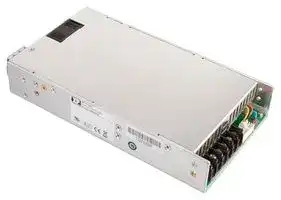
The SMH600 series provide up to 600 W in a low profile (1.6”) chassis mount format. Single outputs are available from 3.3 – 60 VDC and there are three dual output models offering combinations from 5V to 24 VDC. The full power rating is available from 90 – 264 VAC input in ambient temperatures up to 50 °C providing power solutions for global use without the need for de-rating. All models comply with level B for both conducted and radiated emissions.
Dimensions:
SMH:
8.00 x 5.00 x 1.60” (203.0 x 127.0 x 40.64 mm) SMH-EF: 9.10 x 5.00 x 1.60” (231.1 x 127.0 x 40.64 mm) SMH-TF: 8.00 x 5.00 x 2.20” (203.0 x 127.0 x 55.8 mm)
**==> picture [77 x 12] intentionally omitted <==**
**----- Start of picture text -----**<br>
Models & Ratings<br>**----- End of picture text -----**<br>
|Output<br>~~re~~|Output 1(3)<br>~~repeers eee~~|Output 1(3)<br>~~repeers eee~~|Output 2<br>~~eeeee~~|Output 2<br>~~eeeee~~|Model Number(2)<br>~~ee~~|
|---|---|---|---|---|---|
||Voltage<br>~~re~~|Current<br>~~peers eee~~|Voltage<br>~~eee~~|Current<br>~~ee~~||
|330 W<br>~~re~~<br>~~pf~~|3.3 VDC<br>~~re ~~<br>~~pf~~|100.00 A<br> ~~peers eee~~<br>~~pf~~|~~eee ~~<br>~~pf~~|~~ee~~<br>~~pf~~|SMH600PS03<br>~~ee~~<br>~~pf~~|
|500 W<br>~~pT~~|5.0 VDC<br>~~pT~~|100.00 A<br>~~pT~~|~~pT~~|~~pT~~|SMH600PS05<br>~~pT~~|
|600 W<br>~~a~~|12.0 VDC<br>~~OG~~|50.00 A<br>~~OG~~|~~SC~~|~~SC~~|SMH600PS12|
|600 W<br>~~pT~~|15.0 VDC<br>~~pT~~|40.00 A<br>~~pT~~|~~pT~~|~~pT~~|SMH600PS15<br>~~pT~~|
|600 W<br>~~pT~~|18.0 VDC<br>~~pT~~|33.33 A<br>~~pT~~|~~pT~~|~~pT~~|SMH600PS18<br>~~pT~~|
|600 W<br>~~pT~~|24.0 VDC<br>~~pT~~|25.00 A<br>~~pT~~|~~pT~~|~~pT~~|SMH600PS24<br>~~pT~~|
|600 W<br>~~a~~|36.0 VDC<br>~~GG~~|16.60 A<br>~~GG~~|~~GC~~|~~GC~~|SMH600PS36|
|600 W<br>~~pf~~|48.0 VDC<br>~~pf~~|12.50 A<br>~~pf~~|~~pf~~|~~pf~~|SMH600PS48<br>~~pf~~|
|600 W<br>~~pT~~|54.0 VDC<br>~~pT~~|11.10 A<br>~~pT~~|~~pT~~|~~pT~~|SMH600PS54<br>~~pT~~|
|600 W<br>~~pT~~|60.0 VDC<br>~~pT~~|10.00 A<br>~~pT~~|~~pT~~|~~pT~~|SMH600PS60<br>~~pT~~|
|500 W<br>~~a ~~|+5.0 VDC<br> ~~GG~~|50.00 A<br>~~GG~~|+12.0 V<br>~~GG~~|33.33 A<br>~~GG~~|SMH600PD0512<br>~~GG~~|
|500 W<br>~~a~~|+5.0 VDC<br>~~GG~~|50.00 A<br>~~GG~~|+24.0 V<br>~~GG~~|16.67 A<br>~~GG~~|SMH600PD0524|
|600 W<br>~~a~~|+12.0 VDC|33.33 A|+24.0 V|16.67 A|SMH600PD1224|
## ~~**Notes**~~
_1. Add suffix ‘-EF’ to model number for end fan type, ‘-TF’ for top fan type._
## _2. Standard models have screw terminals._
- _For optional Molex input connector add suffix '-F-, for optional Molex output connector add suffix '-G' and for optional Molex input and output connectors add suffix '-FG'. Molex output terminals are not available on 3V3 and 5V single output versions or 0512 and 0524 dual output versions. For optional IEC320-C14 inlet on end fan types add suffix ‘-K’_
_3. Output peak power of 900 W for 500 μ s is available on single output models._
|Characteristic|Minimum|Typical|Maximum|Units|Notes & Conditions|
|---|---|---|---|---|---|
|Input Range|90||264|VAC||
|Signals|||||Power Good|
|Efficiency||90 / 89||%|Single output / Dual output at 230 V and full load|
|Operating Temperature|0||+70|°C|Derate at 2.5%/°C from +50 °C to +70 °C|
|Weight||3.53 (1.6)||lb (kg)|End fan ‘-EF’ version|
|EMC|EN55032 Level B Conducted & Radiated, EN61000-4, EN61000-3|||||
|Safety Approvals|EN62368-1, UL62368-1, CSA62368-1 via cUL|||||
**www.xppower.com**
1
XP Power
Input
**==> picture [431 x 83] intentionally omitted <==**
**----- Start of picture text -----**<br>
|||||||
|---|---|---|---|---|---|
|Characteristic|Minimum|Typical|Maximum|Units|Notes & Conditions|
|Input Voltage|90|264|VAC|
|Input Frequency|47|63|Hz|
|Input Current|6|A|115 VAC (3.0 A at 230 VAC)|
|Inrush Current|70|A|230 VAC (35 A at 115 VAC)|
|Power Factor|>0.9|EN61000-3-2 class A|
|Earth Leakage Current|<1.0|mA|264 VAC|
|Input Protection|T10.0 A/250 V fuse|
**----- End of picture text -----**<br>
Output
**==> picture [538 x 247] intentionally omitted <==**
**----- Start of picture text -----**<br>
||||||||||
|---|---|---|---|---|---|---|---|---|
|pp|Characteristic|Minimum|Typical|Maximum|Units|Notes & Conditions|
|pf|Output Voltage|3.3|60|VDC|See Models and Ratings table|
|Output Voltage Trim|±5|%|V1 (V2 of dual output models will track by same % of|
|adjustment)|
|a|
|pf|Initial Set Accuracy|±1|%|
|pf|Minimum Load|1 / 10|%|Single / Dual (for regulation)|
|p|Start Up DelayStart Up Rise Time|O|40|2.0|f|mss|115 VACPD1224 model typically 50 ms|
|pf|Hold Up Time|10|13|ms|115 VAC|
|pf|Drift|±0.5|%|After 20 min warm up|
|Line Regulation|±0.5|%|
|p|Load Regulation|O|±1 / ±3 / ±5|T|%|Single / Dual V1 / Dual V2 outputs|
|pf|Over/Undershoot|1.5|5|%|
|Transient Response|±5|%|Deviation, recovery to within 1% in 500|μ|s for a 50%|
|load change|
|a|
|a|Ripple & Noise|1|% pk-pk|Measured at 20 MHz BW and 10 and 0.1|μ|F ceramic at terminals|μ|F electrolytic|
|p|Overvoltage Protection|O|130|%|V1 recycle AC input to reset|
|Overload Protection|110|140|f|%|
|pf|Short Circuit Protection - V1|Trip and restart, auto recovery|
|pT|Remote On/Off|Applying short circuit between Remote On/Off pin and signal return turns output off.|
|a|Remote Sense|Compensates for 0.5 V max. voltage drop on single output models only.|
**----- End of picture text -----**<br>
General
**==> picture [537 x 112] intentionally omitted <==**
**----- Start of picture text -----**<br>
||||||||
|---|---|---|---|---|---|---|
|Characteristic|Minimum|Typical|Maximum|Units|Notes & Conditions|
|CC|GCC|
|pf|Efficiency|90 / 89|%|Single output / Dual output at 230 V and full load|
|Isolation: Input to Output|a|3000|VAC|
|Input to Ground|a|1500|VAC|
|pT|Switching FrequencyOutput to Ground|ee|60 / 28|250|VDCkHz|PFC / PWM|
|pf|Power Density|9.37|W/in|[3]|For U Channel Versions|
|pf|Signals|Power Good|
|pf|Mean Time Between Failure|115|kHrs|MIL-HDBK-217F at 25 °C GB|
|CG|Weight|3.53 (1.6)|lb (kg)|End fan ‘-EF’ version|
**----- End of picture text -----**<br>
**www.xppower.com**
2
XP Power
## Environmental
|Characteristic|Minimum|Typical|Maximum|Units|Notes & Conditions|
|---|---|---|---|---|---|
|Operating Temperature|0||+70|°C|Derate at 2.5%/°C from +50 °C to +70 °C|
|Storage Temperature|-20||+85|°C||
|Cooling|||||Forced-cooled. -EF and -EF versions have inbuilt<br>one fan. Speed increases when output exceeds 2 A<br>approx|
|Operating Altitude|||3000|m||
|Vibration|5||50|Hz|Acceleration 7.35 ms2on 3 axes|
EMC: Emissions Phenomenon Standard Test Level Notes & Conditions Conducted EN55032 Level B Radiated EN55032 Level B Harmonic Current EN61000-3-2 Class A Class C for loads ≥ 70% Voltage Flicker EN61000-3-3 ~~————_—__—_—~~ EMC: Immunity Phenomenon Standard Test Level Criteria Notes & Conditions ESD EN61000-4-2 Level 3 A Radiated EN61000-4-3 Level 2 A EFT EN61000-4-4 Level 2 A Surges EN61000-4-5 Installation class 3 A Conducted EN61000-4-6 Level 2 A DIP: 30% 10 ms A Dips and Interruptions EN61000-4-11 DIP: 60% 100 ms A/B Highline (<420 W) / Lowline INT: 100% 5000 ms B ~~—————~~ Safety Approvals Safety Agency Safety Standard Notes & Conditions UL UL62368-1 CSA CSA62368-1 via cUL TUV EN62368-1 CE Meets all applicable directives UKCA Meets all applicable legislation ~~oo~~
**www.xppower.com**
3
## XP Power
**==> picture [535 x 556] intentionally omitted <==**
**----- Start of picture text -----**<br>
Single Model 0.10 (2.50) 9.00 (228.60)<br>C C Pin Description<br>B B RS-RS+ RS- Negative remote sense<br>RSW<br>| —— 7.00 (177.80) Tol 0.50 (12.70) ! : RTNPG \ RS+ Positive remote sense<br>| © s,0 mG) -—-Q_. f s i ‘\<br>RSW Remote On/Off<br>RTN Signal Return<br>PG Power Good<br>B B<br>C C<br>CN3 B: MOUNTING HOLE 8 PLACE<br>6-32 UNC(ZN-PLATED)<br>CN1 CN2<br>P e PSBe i eb ED | pee |<br>C C<br>aeIg o a8 To l oe | B B (Cnic S ian a | S> Ø5.60<br>1.60 (40.64) 1.60 (40.64) OPTIONAL CONNECTOR 6.40<br>| | ral — C lon<br>MOLEX PART NO.09-50-3141 (14 PINS)<br>TERMINAL BLOCKM3 SCREWS3 PINS 8.25 MM CENTER Optional IEC320-C14 Inlet _ _! | || TERMINAL BLOCK6 PINS 9.5 MM CENTER |<br>B B<br>C C<br>| J?ee ls | | C: MOUNTING HOLE 8 PLACE<br>1.50 (38.10) 7.00 (177.80) M4X0.7 (BRASS)<br>Dual Model a<br>0.10 (2.50) 9.00 (228.60)<br>Ø5.90<br>| Ss<br>Qa C —-—& C Te 6.40<br>B B<br>MI| — ©) SO RTE ==== _e8S aels | a RSW<br>7.00 (177.80) 0.50 (12.70) RTNPG<br>B B<br>C C<br>CN3 Pin Description<br>(a) | 7 RSW Remote On/Off<br>Wey) Wa) | Al<br>CN1 CN2 RTN Signal Return<br>LE a SSB (I | ae 7 = PG Power Good<br>ell e 4 | Kel ||| Sy |<br>C C<br>B B<br>Bc ) l leal |e ) 4 -——- a k h Sal<br>| Te t ee EPI . |S<br>1.60 (40.64) 1.60 (40.64) | OPTIONAL CONNECTOR =<br>TERMINAL BLOCK a a Optional IEC320-C14 Inlet re| [al][|] TERMINAL BLOCKMOLEX PART NO.09-50-3141 (14 PINS)<br>M3 SCREWS3 PINS 8.25 MM CENTER | | 6 PINS 9.5 MM CENTER<br>B B<br>C C<br>| 4? eee le )<br>1.50 (38.10) 7.00 (177.80)<br>a 7<br>UNC #6-32<br>M4*0.7P<br>0.80 (20.32)<br>1.25 (31.75)<br>)(127.05.00 VO- VO-<br>VO+ VO+<br>2.70 0.60<br>1.60 (40.64)<br>1.25 (31.75)<br>0.80 (20.32)<br>0.80 (20.32) 2.70 0.60<br>1.25 (31.75)<br>5.00 (127.0) V2RTN V2RTN<br>V1 V1<br>)(31.75<br>1.60 (40.64)<br>1.25<br>)(20.320.80<br>**----- End of picture text -----**<br>
## ~~**Notes**~~
1. All dimensions in inches (mm).
2. Tolerance .xx = ±0.02 (0.50); .xxx = ±0.01 (0.25)
4. Weight: 3.53 lbs (1.6 kg)
5. Fan output not available
3. Maximum mounting screws penetration : 0.15 (3.81) on bottom side and
- 0.25 (6.35) on both sides.
**www.xppower.com**
**SMH600 AC-DC Power Supplies** = ~~<~~
XP Power
**==> picture [535 x 562] intentionally omitted <==**
**----- Start of picture text -----**<br>
Single Model<br>C C<br>B B RS-<br>RS+<br>RSWRTN Pin Description<br>0.50 (12.70) | 7.00 (177.80) 0.50 (12.70) PG 1.60 (40.64) RS- Negative remote sense<br>| ee!_ / | RS+RSW Positive remote senseRemote On/Off<br>e BC ee CB RTN Signal Return<br>MOLEX PART NO.09-50-3071 a 5 CN3 PG Power Good<br>(7 PINS, 5 USED)<br>PIN NO.3,6 NC<br>CN2<br>CN1<br>| | ey) re (i).<br>C C<br>B B B: MOUNTING HOLE 8 PLACE6-32 UNC(ZN-PLATED)<br>OPTIONAL CONNECTOR<br>TERMINAL BLOCK MOLEX PART NO.09-50-3141 (14 PINS)<br>3 PINS 8.25 MM CENTER TERMINAL BLOCK<br>6 PINS 9.5 MM CENTER<br>Ø5.60<br>B B<br>g——_ 1 _, ( COT,<br>C C 6.40<br>>Hi A | | Se<br>CoHA 8.00 (203.20) HI<br>Dual Model C: MOUNTING HOLE 8 PLACE<br>M4X0.7 (BRASS)<br>C C<br>B soa _ 7 B | | _<br>RSW<br>RTNPG Ø5.90<br>0.50 (12.70) 7.00 (177.80) 0.50 (12.70)<br>| 6.40<br>B B<br>[ ganna C rr C 8 Ty]<br>MOLEX PART NO.<br>09-50-3071 , , © ) CN3<br>(7 PINS, 5 USED)<br>PIN NO.3,6 NC<br>CN2 Pin Description<br>CN1 RSW Remote On/Off<br>C C RTN Signal Return<br>B B PG Power Good<br>OPTIONAL CONNECTOR<br>TERMINAL BLOCK MOLEX PART NO.09-50-3141 (14 PINS)<br>3 PINS 8.25 MM CENTER ————— TERMINAL BLOCK<br>— | 6 PINS 9.5 MM CENTER<br>8.00 (203.20)<br>B B<br>C C<br>NNN MN<br>8.00 (203.20)<br>re |<br>UNC #6-32<br>M4*0.7P<br>0.80 (20.32)<br>)(31.751.25<br>3.25 (82.55) 4.00 (101.60) VO- VO- )(127.05.00<br>VO+ VO+<br>)(22.230.88 0.50 (12.70)<br>) 2.70 0.60<br>(55.802.20<br>1.25 (31.75)<br>)(20.320.80<br>0.80 (20.32)<br>1.25 (31.75)<br>2.70 0.60<br>V2 V2 )(127.0<br>3.25 (82.55) 4.00 (101.60) 5.00<br>RTN RTN<br>V1 V1<br>)(22.230.88 0.50 (12.70)<br>2.20 (55.80)<br>1.25 (31.75)<br>)(20.320.80<br>**----- End of picture text -----**<br>
## ~~**Notes**~~
1. All dimensions in inches (mm).
2. Tolerance .xx = ±0.02 (0.50); .xxx = ±0.01 (0.25)
4. Weight: 2.87 lbs (1.3 kg)
5. Fan output not available
3. Maximum mounting screws penetration : 0.15 (3.81) on bottom side and
- 0.25 (6.35) on both sides.
**www.xppower.com**
XP Power
**==> picture [540 x 565] intentionally omitted <==**
**----- Start of picture text -----**<br>
Single Model<br>7 coa E 4 [i 20 FAN<br>C C CN3<br>| B eK] ae B | ( RS-RS+ *<br>RSW<br>RTN<br>PG<br>| S h o7<br>0.50 (12.70) 7.00 (177.80) 0.50 (12.70) hapeaied 1.60 (40.64)<br>B: MOUNTING HOLE 8 PLACE<br>ee | 6-32 UNC(ZN-PLATED)<br>Qo B B Pin Description<br>C C<br>MOLEX PART NO. PT | FAN | RS- Negative remote sense<br>09-50-3071 CN3 RS+ Positive remote sense<br>(7 PINS, 5 USED)<br>PIN NO.3,6 NC : : 4 71 ° Ø5.60 RSW Remote On/Off<br>CN1 CN2 RTN Signal Return<br>Tel ee 5 a 6.40 PG Power Good<br>C C<br>| | B B cay | rio<br>OPTIONAL CONNECTOR<br>TERMINAL BLOCK een MOLEX PART NO.09-50-3141 (14 PINS) {eT<br>3 PINS 8.25 MM CENTER TERMINAL BLOCK C: MOUNTING HOLE 8 PLACE<br>6 PINS 9.5 MM CENTER M4X0.7 (BRASS)<br>| |<br>B B<br>C C<br>SHIAN MN | |<br>Ø5.90<br>8.00 (203.20)<br>6.40<br>Dual Model<br>int Con g oy 7S<br>C C FAN<br>B B CN3<br>ooo —-—-°3-6-9 o m RSWRTN |<br>PG<br>0.50 (12.70) i | 7.00 (177.80) LO 0.50 (12.70) N E U 1.60 (40.64)<br>Qo B B<br>C C<br>MOLEX PART NO. || FAN<br>09-50-3071 CN3 Pin Description<br>(7 PINS, 5 USED)PIN NO.3,6 NC I RSW Remote On/Off<br>| | CN1 CN2 Teeie } 1 RTN Signal Return<br>PG Power Good<br>Y| # Il C C lelely ||| —=<br>ar B B<br>OPTIONAL CONNECTOR<br>TERMINAL BLOCK | P|| MOLEX PART NO.09-50-3141 (14 PINS)<br>3 PINS 8.25 MM CENTER TERMINAL BLOCK<br>6 PINS 9.5 MM CENTER<br>|<br>O g B ——8g 9 B ®<br>C C<br>ttt<br>8.00 (203.20)<br>Le t™—“CO IrSYS |<br>UNC #6-32<br>M4*0.7P<br>0.80 (20.32)<br>)(31.751.25<br>2.70 0.60<br>3.25 (82.55) 4.00 (101.60) VO- VO- 5.00 (127.0)<br>VO+ VO+<br>)(22.230.88 0.50 (12.70)<br>1.25 (31.75)<br>2.70 0.60<br>0.80 (20.32)<br>0.80 (20.32)<br>1.25 (31.75)<br>V2 V2<br>3.25 (82.55) 4.00 (101.60) 5.00 (127.0)<br>RTN RTN<br>V1 V1<br>0.88 (22.23) )(12.700.50<br>1.25 (31.75)<br>0.80 (20.32)<br>**----- End of picture text -----**<br>
## ~~**Notes**~~
1. All dimensions in inches (mm).
2. Tolerance .xx = ±0.02 (0.50); .xxx = ±0.01 (0.25)
3. Maximum mounting screws penetration : 0.15 (3.81) on bottom side and 0.25 (6.35) on both sides.
4. Weight: 2.65 lbs (1.2 kg)
**www.xppower.com**
14 Oct 2021
Updated at February 9, 2023
XP Power is a globally recognized leader in the design and manufacture of critical power solutions for the electronics industry. With a steadfast commitment to total quality and in-house engineering expertise, the company delivers highly reliable components that support complex applications across the industrial, healthcare, and technology sectors. Their extensive manufacturing capabilities provide engineers with a broad and dependable source for innovative power products. Our extensive portfolio of XP Power components is heavily focused on robust power and line protection. The core of this offering features a vast selection of high-performance AC/DC converters, designed to meet the rigorous efficiency and footprint demands of modern electronic systems. Complementing these are numerous reliable DC/DC converters, providing versatile options for precise voltage regulation and seamless system integration. Beyond their primary power conversion ranges, XP Power manufactures specialized components to address specific design challenges. Our selection includes essential passive components, such as power line filters for effective EMC and RFI suppression, ensuring signal integrity and strict regulatory compliance. Additionally, we provide dedicated AC/DC LED power supplies tailored for reliable, long-lasting performance in advanced commercial and industrial lighting applications.
About Novapart
Novapart is a B2B electronic component broker specialising in stock shortages and cost reduction. We source hard-to-find parts and identify compliant alternatives across a catalogue of 410,000+ components from 500+ manufacturers.
Learn more →Stock Shortage Specialist
When a component is unavailable, discontinued or has an unacceptable lead time, we tap into our network of vetted European and Asian distributors to source what you need — without compromising on quality or traceability.
Request a quote →Compliant Alternatives
We identify pin-to-pin, electrically equivalent substitutes that meet the same certifications (RoHS, AEC-Q100, REACH) as your original specification — validated against datasheets, not just part numbers. Often at a lower cost.
BOM Analysis service →