
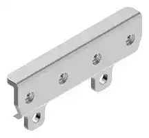


SMBR90S
Mounting Bracket, DXMR90 Series Controllers, Stainless Steel
- Manufacturer: BANNER ENGINEERING
- Product type:
- SVHC: No SVHC (15-Jan-2018)
- For Use With: Banner Engineering DXMR90 Series Controllers
| Delivery and price | |
|---|---|
| Units per pack | 1 |
| Price | 22.39 € |
| Current stock | 10+ |
| Lead time | 30 days |
## DXMR90 Series Controller

## Datasheet

The DXMR90 Series Controller is an industrial controller within the Banner DXM family of controllers that consolidates, processes, and distributes data using industrial or web services protocols.

   - Configurable controller works with a wide range of Modbus devices; quickly deploy Modbus slave device data to EtherNet/IP[™] , Modbus[®] TCP, or PROFINET[®] Networks 1

      - Four independent Modbus master ports per converter increase simplicity and decrease deployment time for co-located assets

      - Connect up to four Modbus slave devices without manually assigning a slave address to connected devices

   - Local control or connectivity with:

      - Automation protocols including EtherNet/IP, PROFINET, Modbus/ TCP, and Modbus RTU

      - Internet protocols including RESTful API and MQTT with web services from AWS

- Logic processing and problem solving capable of deploying solutions to process and control data from multiple devices

- Compact housing saves space and weight compared to traditional "block" style form factors

- IP67 housing simplifies installation in any location by eliminating the need for a control cabinet

- Consolidate cable runs to minimize cabling and associated weight, especially in weight critical applications such as robotics

- Flexible and Customizable—Expanded internal logic controller with action rules, MicroPython, and ScriptBasic programming

## Models

|**Model**|**Ethernet Connection**|**Modbus Master Connections**|**Other Connections**|
|---|---|---|---|
|**DXMR90-X1**|One female M12 D-Code Ethernet<br>Connector|Four female M12 connections for<br>Modbus master connections|One male M12 (Port 0) for incoming power and<br>Modbus RS-485, one female M12 for daisy chaining<br>Port 0 signals.|


## Overview

Banner's DXMR90 Series Controller consolidates data from multiple sources to provide local data processing as well as accessibility for host systems as a platform for the Industrial Internet of Things (IIoT).

The DXMR90 contains four individual Modbus masters allowing for concurrent communication to up to four independent networks. Data is collected into the internal logic controller to facilitate edge processing, protocol conversion to Industrial Ethernet, and pushing information to web servers.

**==> picture [371 x 147] intentionally omitted <==**

**----- Start of picture text -----**<br>
Figure 1. Overview of the DXMR90 Series Controller<br>Configurable<br>Modbus<br>Port 0<br>(female)<br>Configurable<br>Modbus Port 0<br>and Power (male)<br>Modbus Master D-coded Ethernet<br>Ports 1-4 6 (female)<br>(female)<br>**----- End of picture text -----**<br>


One male M12 connection provides common power and ground to all M12 Modbus ports. The two port 0 Modbus connections can be configured as pass-through wiring to connect to a Modbus trunk. One 100 Mbps Ethernet port (female) using an M12 D-coded Ethernet connection.

- Modbus TCP

- EtherNet /IP

> 1 EtherNet/IP[™] is a trademark of ODVA, Inc. Modbus[®] is a registered trademark of Schneider Electric USA, Inc. PROFINET[®] is a registered trademark of PROFIBUS Nutzerorganisation e.V.

Original Document 223673 Rev. A

9 November 2021

223673

DXMR90 Series Controller

- Profinet

- Configuration/discovery port

Four Modbus master connections using female M12 connectors.

- 2-wire RS-485 physical transceiver with power/ground at each connector

- Separate Modbus master control and programmability for each connection point

- Independent and selectable baud rate and parity settings

- Individual timing and packet timing for each Modbus connection

## Installation Instructions

## Mechanical Installation

Install the DXMR90 to allow access for functional checks, maintenance, and service or replacement.

All mounting hardware is supplied by the user. Fasteners must be of sufficient strength to guard against breakage. Use of permanent fasteners or locking hardware is recommended to prevent the loosening or displacement of the device. The mounting hole (4.5 mm) in the DXMR90 accepts M4 (#8) hardware. See the figure below to help in determining the minimum screw length.

**==> picture [244 x 120] intentionally omitted <==**

**----- Start of picture text -----**<br>
16.0 mm<br>X<br>3 mm *<br>NUT<br> * for minimum<br>Screw Length = 16.0 mm + “X” mm + 3 mm engagement of<br>three threads<br>**----- End of picture text -----**<br>


**CAUTION:** Do not overtighten the DXMR90's mounting screw during installation. Overtightening can affect the performance of the DXMR90.

## Wiring

_Table 1: Ports 0-4 female connector_

|**Port 0–4 5-pin M12 Connector (female)**|**Pin**|**Wire Color**|**Description**|
|---|---|---|---|
|**2**<br>**3**<br>**4**<br>**1**<br>**5**|1|Brown (bn)|12 V DC to 30 V DC|
||2|White (wh)|RS485 / D1 / B / +|
||3|Blue (bu)|DC common (GND)|
||4|Black (bk)|RS485 / D0 / A / -|
||5|Gray (gy)|Not used/reserved|


_Table 2: Port 0 male connector_

|**Port 0 4-pin M12 Connector (male)**|**Pin**|**Wire Color**|**Description**|
|---|---|---|---|
|**1**<br>**4**<br>**3**<br>**2**|1|Brown (bn)|12 V DC to 30 V DC|
||2|White (wh)|RS485 / D1 / B / +|
||3|Blue (bu)|DC common (GND)|
||4|Black (bk)|RS485 / D0 / A / -|


P/N 223673 Rev. A

2

www.bannerengineering.com - Tel: + 1 888 373 6767

DXMR90 Series Controller

_Table 3: D-coded industrial Ethernet connector_

|**4-pin Industrial Ethernet Connector (female)**|**Pin**|**Wire Color**|**Description**|
|---|---|---|---|
|1<br>4<br>3<br>2|1|Black (bk)|+Tx|
||2|Red (rd)|+Rx|
||3|Green (gn)|–Tx|
||4|White (wh)|–Rx|


## Specifications

**Supply Voltage** 12 V DC to 30 V DC

**Supply Protection Circuitry** Protected against reverse polarity and transient voltages

## **Power Consumption**

120 mA maximum at 12 V DC

## **Construction**

Connector Body: PVC translucent black

## **Indicators**

Amber: Power port 0 Amber: Modbus communications port 0-4 Green/amber: Ethernet communications Red/amber/green: User configurable LEDs

## **Connections**

Five integral 5-pin M12 female quick disconnect One integral 4-pin M12 male quick disconnect One integral 5-pin M12 female D-Code quick disconnect

## **Application Note**

When connecting external devices through the DXMR90, it is important not to exceed maximum current limitations of 3.5 Amps

## **Communication Protocols**

Modbus[®] RTU, Modbus/TCP, EtherNet/IP[™] , and PROFINET[®] 2

## **Security Protocols**

TLS, SSL, HTTPS

## **Environmental Ratings**

For Indoor Use Only IP65, IP67, NEMA 1, UL Type 1

## **Operating Conditions**

–40 °C to +70 °C (–40 °F to +158 °F)

90% at +70 °C maximum relative humidity (non-condensing)

## **Storage Temperature**

–40 °C to +80 °C (–40 °F to +176 °F)

## **Vibration and Mechanical Shock**

Meets IEC 60068-2-6 requirements (Vibration: 10 Hz to 55 Hz, 1.0 mm amplitude, 5 minutes sweep, 30 minutes dwell)

Meets IEC 60068-2-27 requirements (Shock: 30G 11 ms duration, half sine wave)

## **Communication Hardware (RS-485)**

Interface: 2-wire half-duplex RS-485 Baud rates: 1.2K, 2.4K, 9.6k, 19.2k (default), 38.4k, 57.6K, or 115.2K Data format: 8 data bits, no parity, 1 stop bit

## **Required Overcurrent Protection**

**WARNING:** Electrical connections must be made by qualified personnel in accordance with local and national electrical codes and regulations.

Overcurrent protection is required to be provided by end product application per the supplied table.

Overcurrent protection may be provided with external fusing or via Current Limiting, Class 2 Power Supply.

Supply wiring leads < 24 AWG shall not be spliced.

For additional product support, go to www.bannerengineering.com.

|**Supply Wiring (AWG)**|**Required Overcurrent Protection (Amps)**|
|---|---|
|20|5.0|
|22|3.0|
|24|2.0|
|26|1.0|
|28|0.8|
|30|0.5|


EtherNet/IP[™] is a trademark of ODVA, Inc. Modbus[®] is a registered trademark of Schneider Electric USA, Inc. PROFINET[®] is a registered trademark of PROFIBUS Nutzerorganisation e.V.

2

P/N 223673 Rev. A

www.bannerengineering.com - Tel: + 1 888 373 6767

3

DXMR90 Series Controller

## Dimensions

All measurements are listed in millimeters, unless noted otherwise.

_Figure 2. R90x1 dimensions_

**==> picture [344 x 215] intentionally omitted <==**

**----- Start of picture text -----**<br>
16 mm<br>[0.63”]<br>16.3 mm<br>[0.64”]<br>20 mm 20 mm 20 mm<br>[0.79”] [0.79”] [0.79”]<br>121.7 mm<br>[4.79”]<br>12.3 mm<br>[0.48”]<br>63.5 mm<br>32.3 mm [2.5”] 32.3 mm<br>[1.27”] 50.5 mm [1.27”]<br>[1.99”]<br>8 mm<br>[0.32”] M12 x 1 40 mm[1.57”] 4.5 mm dia[0.18”] 6x M12 x 1 (Female)<br>(Male)<br>**----- End of picture text -----**<br>


## Accessories

|**4-Pin Threaded M12 Cordsets—Double Ended**|**4-Pin Threaded M12 Cordsets—Double Ended**|**4-Pin Threaded M12 Cordsets—Double Ended**|**4-Pin Threaded M12 Cordsets—Double Ended**|||
|---|---|---|---|---|---|
|**Model**|**Length**|**Style**|**Dimension**|**s**|**Pinout**|
|**MQDEC-401SS**|0.31 m (1 ft)|Male Straight/<br>Female Straight|40 Typ.<br>[1.58"]<br>ø 14.5 [0.57"]<br>M12 x 1<br>44 Typ.<br>[1.73"]<br>ø 14.5 [0.57"]<br>M12 x 1||Female<br>**2**<br>**3**<br>**4**<br>**1**<br>Male<br>**1**<br>**4**<br>**3**<br>**2**<br>1 = Brown<br>2 = White<br>3 = Blue<br>4 = Black|
|**MQDEC-403SS**|0.91 m (2.99 ft)|||||
|**MQDEC-406SS**|1.83 m (6 ft)|||||
|**MQDEC-412SS**|3.66 m (12 ft)|||||
|**MQDEC-420SS**|6.10 m (20 ft)|||||
|**MQDEC-430SS**|9.14 m (30.2 ft)|||||
|**MQDEC-450SS**|15.2 m (49.9 ft)|||||
|**MQDEC-403RS**|0.91 m (2.99 ft)|Male Right-Angle/<br>Female Straight|44 Typ.<br>[1.73"]<br>ø 14.5 [0.57"]<br>M12 x 1<br>32 Typ.<br>[1.26"]<br>30 Typ.<br>[1.18"]<br>ø 14.5 [0.57"]<br>M12 x 1|||
|**MQDEC-406RS**|1.83 m (6 ft)|||||
|**MQDEC-412RS**|3.66 m (12 ft)|||||
|**MQDEC-420RS**|6.10 m (20 ft)|||||
|**MQDEC-430RS**|9.14 m (30.2 ft)|||||
|**MQDEC-450RS**|15.2 m (49.9 ft)|||||


P/N 223673 Rev. A

www.bannerengineering.com - Tel: + 1 888 373 6767

4

DXMR90 Series Controller

|**5-Pin Threaded M12 Cordsets—Single Ended**<br>~~Dd~~<br>~~a~~|**5-Pin Threaded M12 Cordsets—Single Ended**<br>~~Dd~~<br>~~a~~|**5-Pin Threaded M12 Cordsets—Single Ended**<br>~~Dd~~<br>~~a~~|**5-Pin Threaded M12 Cordsets—Single Ended**<br>~~Dd~~<br>~~a~~|**5-Pin Threaded M12 Cordsets—Single Ended**<br>~~Dd~~<br>~~a~~|
|---|---|---|---|---|
|**Model**<br>~~a~~|**Length**|**Style**|**Dimensions**|**Pinout (Female)**|
|**MQDC1-501.5**<br>~~a~~|0.5 m (1.5 ft)|Straight|**44 Typ.**<br>**ø 14.5**<br>**M12 x 1**<br>=~~a~~|**2**<br>**3**<br>**4**<br>**1**<br>**5**<br>1 = Brown<br>2 = White<br>3 = Blue<br>4 = Black<br>5 = Gray|
|**MQDC1-506**|2 m (6.5 ft)||||
|**MQDC1-515**|2 m (6.5 ft)<br>5 m (16.4 ft)||||
|**MQDC1-530**|5 m (16.4 ft)<br>9 m (29.5 ft)||||
|**MQDC1-506RA**|2 m (6.5 ft)|Right-Angle|**32 Typ.**<br>**[1.26"]**<br>**30 Typ.**<br>**[1.18"]**<br>**ø 14.5 [0.57"]**<br>**M12 x 1**<br>~~it~~<br>ca~~l~~||
|**MQDC1-515RA**|5 m (16.4 ft)||||
|**MQDC1-530RA**|9 m (29.5 ft)||||


**==> picture [499 x 390] intentionally omitted <==**

**----- Start of picture text -----**<br>
4-Pin Threaded M12 RS-485 to USB Adapter Cordset, with Wall Plug<br>a<br>Model Length Style Dimensions Pinout (Female)<br>a a<br>2 4<br>1 3<br>BWA-UCT-900 1 m (3.28 ft) Straight<br>1 = Brown<br>2 = White<br>3 = Blue<br>4 = Black<br>4-pin M12 D-code to RJ45 Shielded Ethernet<br>Dd<br>Model Length Style Dimensions Pinout (Male)<br>SC<br>STP-M12D-406 1.83 m (6 ft)<br>STP-M12D-415 4.57 m (15 ft) 2 1<br>RJ45<br>STP-M12D-430 9.14 m (30 ft) Straight 7 47.4 Typ. 1 = White/ : 3 © 1 = White/ 4<br>Orange Orange<br>2 = Orange 2 = White/Blue<br>3 = White/Blue 3 = Orange<br>M12 x 1.0 - 6g 6 = Blue 4 = Blue<br>ø 14.5<br>SMBR90S 8.6 B<br>• Stainless steel bracket<br>• 4x M4-07 pemnuts (B)<br>• Includes 2x M4 stainless<br>steel hex head screws and 74<br>flat washers A<br>Hole center spacing:  A = 40, B = 20<br>Hole size:  A = ø 5 ©a<br>24<br>10.1 a<br>**----- End of picture text -----**<br>


## **Power Supplies**

PSD-24-4—DC Power Supply, Desktop style, 3.9 A, 24 V DC, Class 2, 4-pin M12/Euro-style quick disconnect (QD)

P/N 223673 Rev. A

www.bannerengineering.com - Tel: + 1 888 373 6767

5

DXMR90 Series Controller

PSDINP-24-06—DC power supply, 0.63 Amps, 24 V DC, with DIN Rail Mount, Class I Division 2 (Groups A, B, C, D) Rated PSDINP-24-13 —DC power supply, 1.3 Amps, 24 V DC, with DIN Rail Mount, Class I Division 2 (Groups A, B, C, D) Rated PSDINP-24-25 — DC power supply, 2.5 Amps, 24 V DC, with DIN Rail Mount, Class I Division 2 (Groups A, B, C, D) Rated PSW-24-1—DC power supply with multi-blade wall plug, 100–240 V AC 50/60 Hz input, 24 V DC 1 A output, UL Listed Class 2, 4-pin female M12 connector

PSWB-24-1—DC power supply with multi-blade wall plug,100–240 V AC 50/60 Hz input, 24 V DC 1 A output, UL Listed Class 2, barrel jack connector

## Banner Engineering Corp. Limited Warranty

Banner Engineering Corp. warrants its products to be free from defects in material and workmanship for one year following the date of shipment. Banner Engineering Corp. will repair or replace, free of charge, any product of its manufacture which, at the time it is returned to the factory, is found to have been defective during the warranty period. This warranty does not cover damage or liability for misuse, abuse, or the improper application or installation of the Banner product.

**THIS LIMITED WARRANTY IS EXCLUSIVE AND IN LIEU OF ALL OTHER WARRANTIES WHETHER EXPRESS OR IMPLIED (INCLUDING, WITHOUT LIMITATION, ANY WARRANTY OF MERCHANTABILITY OR FITNESS FOR A PARTICULAR PURPOSE), AND WHETHER ARISING UNDER COURSE OF PERFORMANCE, COURSE OF DEALING OR TRADE USAGE.**

This Warranty is exclusive and limited to repair or, at the discretion of Banner Engineering Corp., replacement. **IN NO EVENT SHALL BANNER ENGINEERING CORP. BE LIABLE TO BUYER OR ANY OTHER PERSON OR ENTITY FOR ANY EXTRA COSTS, EXPENSES, LOSSES, LOSS OF PROFITS, OR ANY INCIDENTAL, CONSEQUENTIAL OR SPECIAL DAMAGES RESULTING FROM ANY PRODUCT DEFECT OR FROM THE USE OR INABILITY TO USE THE PRODUCT, WHETHER ARISING IN CONTRACT OR WARRANTY, STATUTE, TORT, STRICT LIABILITY, NEGLIGENCE, OR OTHERWISE.**

Banner Engineering Corp. reserves the right to change, modify or improve the design of the product without assuming any obligations or liabilities relating to any product previously manufactured by Banner Engineering Corp. Any misuse, abuse, or improper application or installation of this product or use of the product for personal protection applications when the product is identified as not intended for such purposes will void the product warranty. Any modifications to this product without prior express approval by Banner Engineering Corp will void the product warranties. All specifications published in this document are subject to change; Banner reserves the right to modify product specifications or update documentation at any time. Specifications and product information in English supersede that which is provided in any other language. For the most recent version of any documentation, refer to: www.bannerengineering.com.

For patent information, see www.bannerengineering.com/patents.

© Banner Engineering Corp. All rights reserved
Updated at June 9, 2026
Founded in 1966, Banner Engineering is a globally recognized leader in the design and manufacture of industrial automation products. The company is renowned for developing innovative, high-quality solutions that improve operational efficiency, safeguard personnel, and optimize manufacturing processes across a diverse range of industries. Our extensive selection of Banner Engineering components prominently features their industry-leading sensing technologies. We offer a comprehensive array of precision light sensors engineered for accurate detection and measurement in demanding environments. Complementing this core sensing portfolio is a robust offering of automation signaling devices, including visual signal indicator units and essential accessories, which provide clear and immediate communication of machine status. Beyond primary sensing and indication solutions, our range encompasses critical components for broader process control and machine safety. This includes advanced process controllers, reliable pressure sensors and transducers, and dependable safety relays. Supported by a variety of purpose-built sensor accessories and fiber optic lead assemblies, Banner Engineering delivers the durable, high-performance technologies required to build and maintain sophisticated automated systems.
About Novapart
Novapart is a B2B electronic component broker specialising in stock shortages and cost reduction. We source hard-to-find parts and identify compliant alternatives across a catalogue of 410,000+ components from 500+ manufacturers.
Learn more →Stock Shortage Specialist
When a component is unavailable, discontinued or has an unacceptable lead time, we tap into our network of vetted European and Asian distributors to source what you need — without compromising on quality or traceability.
Request a quote →Compliant Alternatives
We identify pin-to-pin, electrically equivalent substitutes that meet the same certifications (RoHS, AEC-Q100, REACH) as your original specification — validated against datasheets, not just part numbers. Often at a lower cost.
BOM Analysis service →