
Image not available
Illustrative purposes only

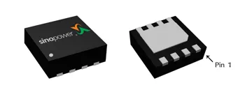
SM9990DSQG
SM9990DSQG, Dual MOSFET, N Channel, 20V, DFN2x2A-8_EP
⚠️ Reference pricing provided. In case of supply shortages, we will connect you with our trusted procurement partners to ensure your project's continuity.
- Manufacturer: Sinopower
- Product type: Dual MOSFETs
- Cfg.: Dual N
- BV(V): 20
- 4V max.: 31
- Package: DFN2x2A-8_EP
- 2.5V max.: 42
- 3.1V max.: 36
- VGS (±V): 12
- VTH(V) typ.: 0.7
- ID (A) TC=25: 6.2
- Rg (Ω) typ.: 5
- Ciss (pF) typ.: 460
- Coss (pF) typ.: 115
- Crss (pF) typ.: 105
| Delivery and price | |
|---|---|
| Units per pack | 1 |
| Price | Ask for quotation |
| Current stock | 10+ |
| Lead time | 30 days |
Datasheet

**®** sinopower N ## **SM999 0DSQG** Dual N-Channel Enhancement Mode MOSFET ## **Features** ## **Pin Description** - 20V/6.2A, - RDS(ON)= 31m Ω (Max.) @ VGS=4V RDS(ON)= 36m Ω (Max.) @ VGS=3.1V RDS(ON)= 42m Ω (Max.) @ VGS=2.5V - Reliable and Rugged - Lead Free and Green Devices Available (RoHS Compliant) DFN2x2-8 (top/bottom) - ESD Protection ## **Applications** - Power Management in Notebook Computer, Portable Equipment and Battery Powered Systems. **==> picture [135 x 126] intentionally omitted <==** **----- Start of picture text -----**<br> D(5) D(6) D(7) D(8)<br>(2) (4)<br>G1 G2<br>S1(1) S2(3)<br>**----- End of picture text -----**<br> N-Channel MOSFET ## **Ordering and Marking I nform ation** **==> picture [390 x 112] intentionally omitted <==** **----- Start of picture text -----**<br> SM9990DS OOO -O O0O Package Code<br> QG : DFN2x2-8<br>Assembly Material<br>Operating Junction Temperature Range<br>Handling Code C : -55 to 150 [o] C<br>Handling Code<br>Temperature Range TR : Tape & Reel (3000ea/reel)<br>= Assembly Material<br>Package Code<br> G : Halogen and Lead Free Device<br>SM9990DS QG : 9990I XXXX - Lot Code<br>XXXX<br>**----- End of picture text -----**<br> Note: SINOPOWER lead-free products contain molding compounds/die attach materials and 100% matte tin plate termination finish; which are fully compliant with RoHS. SINOPOWER lead-free products meet or exceed the lead-free **-** requirements of IPC/JEDEC J STD-020D for MSL classification at lead-free peak reflow temperature. SINOPOWER defines “Green” to mean lead-free (RoHS compliant) and halogen free (Br or Cl does not exceed 900ppm by weight in homogeneous material and total of Br and Cl does not exceed 1500ppm by weight). SINOPOWER reserves the right to m ake changes to im prove reliability or m anufacturability without notice, and advise custom ers to obtain the latest version of relevant inform ation to verify before placing orders. _ww w.sinopowersem i.com_ 1 Copyright Sinopower Sem iconductor, Inc. Rev. A.5 - Decem ber, 2014 **®** sinopower MA ## **SM999 0DSQG** ## **Absolute Maxim um Ratings** (TA = 25 ° C Unless Otherwise Noted) |**Symbol**|**Parameter**|**Parameter**|**Rating**|**Unit**| |---|---|---|---|---| |VDSS|Drain-Source Voltage||20|V| |VGSS|Gate-Source Voltage||±12|| |ID*|Continue Drain Current|TC=25°C|6.2**|A| |||TC=70°C|5|| |IDM*|Pulsed Drain Current|TC=25°C|24|| |IS*|Diode continuous forward current||1.5|A| |TJ|Maximum Junction Temperature||150|°C| |TSTG|Storage Temperature Range||-55 to 150|| |PD|Maximum Power Dissipation|TA=25°C|1.8|W| |||TA=70°C|1.1|| Note *:Surface Mounted on 1in[2 ] pad area, t ≤ 10sec. Note **:Current limited by bond wire. ## **Electrical Characteristics** (TA = 25 ° C Unless Otherwise Noted) |||~~es~~|~~es~~||||| |---|---|---|---|---|---|---|---| |**Symbol**<br>~~a~~|**Parameter**<br>~~es~~|**Test Conditions**<br>~~es~~<br>~~es~~||**Min.**<br>~~es~~|**Typ.**<br>~~es~~|**Max.**<br>~~es~~|**Unit**<br>~~es~~| |**Static Characteristics**<br>~~es~~<br>~~Cn~~|||||||| |BVDSS<br>~~a~~|Drain-Source Breakdown Voltage<br>~~a~~|VGS=0V, IDS=250µA<br>~~a~~<br>~~**e**e~~||20<br>~~a~~<br>|-<br>~~a~~<br>~~oe~~|-<br>~~a~~<br>~~oe~~|V<br>~~a~~<br>~~oe~~| |IDSS<br>~~a~~|Zero Gate Voltage Drain Current<br>~~a~~|VDS=16V, VGS=0V<br>TJ=85°C<br>~~a~~<br>~~**e**e~~<br>~~|~~||-<br>~~a~~<br><br>~~|~~|-<br>~~a~~<br>~~oe~~<br>~~||~~|1<br>~~a~~<br>~~oe~~<br>~~|~~|µA<br>~~a~~<br>~~oe~~| ||||TJ=85°C<br>~~a~~<br>~~e~~<br>~~|~~|-<br>~~a~~<br><br>~~|~~<br>~~|~~|-<br>~~a~~<br>~~oe~~<br>~~|~~<br>~~||~~|30<br>~~a~~<br>~~oe~~<br>~~|~~<br>~~|~~|| |VGS(th)<br>~~G~~|Gate Threshold Voltage<br>~~G~~|VDS=VGS, IDS=250µA<br>~~**e**e~~<br>~~G~~||0.5<br><br>~~|~~|0.7<br>~~oe~~<br>~~| |~~|1<br>~~oe~~<br>~~|~~|V<br>~~oe~~| |IGSS<br>~~a~~|Gate Leakage Current|VGS=±10V, VDS=0V<br>~~**e**e ~~||-<br> <br>~~ee~~|-<br> ~~oe~~|±10<br>~~oe~~|µA<br>~~oe~~| |RDS(ON)<br>a<br>~~Ce~~|Drain-Source On-state Resistance<br>|VGS=4V, IDS=2A<br>~~ee~~||-<br>~~ee~~<br>~~ee~~<br>~~ee~~|23.5<br>~~ee~~<br>~~ee~~|31<br>~~ee~~<br>~~ee~~|mΩ| |||VGS=3.1V, IDS=1.6A<br>~~ee~~||-<br>~~ee~~<br>~~ee~~<br>~~ee~~<br>~~ee~~|27<br>~~ee~~<br>~~ee~~|36<br>~~ee~~<br>~~ee~~|| |||VGS=2.5V, IDS=1A<br>~~ee~~||-<br>~~ee ~~<br>~~ee~~<br>~~ee~~|30<br> ~~ee~~<br>~~ee~~|42<br>~~ee~~<br>~~ee~~|| |**Diode Characteristics**<br>~~ee~~<br>~~Ce~~|||||||| |VSD<br>a<br>~~CeaSn~~|Diode Forward Voltage<br>~~Sn~~|ISD=3A, VGS=0V<br>~~ee~~||-<br>~~ee~~|0.8|1.3|V| |trr<br>~~Sn~~<br>~~a~~|Reverse Recovery Time<br>~~Sn~~|ISD=6A, dISD/dt=100µs<br>~~ee~~<br>~~—~~||-<br>~~—tf~~|10.6<br>~~tf~~<br>~~|~~|-<br>~~|~~|nS<br>~~|~~| |Qrr<br>~~Sn~~<br>~~a~~|Reverse Recovery Charge<br>~~Sn~~|||-<br>~~—tf~~|3.2<br>~~tf~~<br>~~|~~|-<br>~~|~~|nC<br>~~|~~| _ww w.sinopowersem i.com_ 2 Copyright Sinopower Sem iconductor, Inc. Rev. A.5 - Decem ber, 2014 **®** sinopower MA ## **SM999 0DSQG** **Electrical Characteristics ( Cont.)** (TA = 25 ° C Unless Otherwise Noted) |**Symbol**<br>~~a~~|**Parameter**<br>~~ss~~|**Test Conditions**<br>~~ss~~|**Min.**<br>~~ss~~|**Typ.**<br>~~ss~~|**Max.**<br>~~ss~~|**Unit**<br>~~ss~~| |---|---|---|---|---|---|---| |**Dynamic Characteristics**<br>b||||||| |RG<br>~~a~~<br>~~rs~~|Gate Resistance|VGS=0V,VDS=0V,F=1MHz<br>~~**|**~~|-<br>~~**|**~~|5|-|Ω| |Ciss<br>~~rs~~<br>~~a~~|Input Capacitance<br>~~ee~~|VGS=0V,<br>VDS=10V,<br>Frequency=1.0MHz<br>~~**|**~~<br>~~ee~~<br>~~|~~|-<br>~~**|**~~<br>~~|~~<br>~~**|**~~|460|-|pF| |Coss<br>~~rs~~<br>~~a~~<br>~~ee~~|Output Capacitance<br>~~ee~~||-<br>~~**|**~~<br>~~|~~<br>~~**|**~~<br>~~|~~|115<br>~~|~~|-<br>~~|~~|| |Crss<br>~~a~~<br>~~ee~~<br>~~ee~~|Reverse Transfer Capacitance<br>~~ee~~||-<br>~~|~~<br>~~**|**~~<br>~~|~~<br>~~|~~|105<br>~~|~~<br>~~|~~|-<br>~~|~~<br>~~|~~|| |td(ON)<br>~~ee~~<br>~~ee~~<br>~~ee~~|Turn-on DelayTime|VDD=10V, RL=10Ω,<br>IDS=1A, VGEN=4.5V,<br>RG=6Ω<br>~~ee~~<br>~~**|**~~|-<br>~~| ~~<br>~~|~~<br>~~pt~~|4.5<br> ~~|~~<br>~~|~~<br>~~pt|~~|-<br>~~|~~<br>~~|~~<br>~~|~~|ns| |tr<br>~~ee~~<br>~~ee~~<br>~~a~~|Turn-on Rise Time<br>~~ee~~||-<br>~~| ~~<br>~~pt~~<br>~~pf~~|14<br> ~~|~~<br>~~pt|~~<br>~~pf~~|-<br>~~|~~<br>~~|~~<br>~~pf~~|| |td(OFF)<br>~~ee~~<br>~~a~~<br>~~a~~|Turn-off DelayTime<br>~~ee~~||-<br>~~pt~~<br>~~pf~~<br>~~**|**~~|26<br>~~pt |~~<br>~~pf~~|-<br>~~|~~<br>~~pf~~|| |tf<br>~~a~~<br>~~a~~|Turn-off Fall Time<br>~~ee~~||-<br>~~pf~~<br>~~**|**~~|6<br>~~pf~~|-<br>~~pf~~|| |**Gate Charge Characteristics**<br>b<br>~~a~~<br>~~**|**~~<br>~~a~~<br>~~|~~||||||| |Qg<br>~~a~~|Total Gate Charge|VDS=10V, VGS=4.5V,<br>IDS=6A<br>~~|~~<br>~~ee~~<br>~~|~~<br>~~ee~~<br>~~|~~|-<br>~~|||~~|7.5<br>~~||~~|-<br>~~||~~|nC| |Qgs<br>~~a~~<br>~~rs~~<br>~~a~~|Gate-Source Charge<br>~~ee~~<br>~~ee~~||-<br>~~|~~<br>~~|ft~~<br>~~|~~<br>~~ft~~|0.3<br><br>~~ft|~~<br>~~ft~~|-<br><br>~~|~~<br>|| |Qgd<br>~~rs~~<br>~~a~~|Gate-Drain Charge<br>~~ee~~<br>~~ee~~||-<br>~~| ft~~<br>~~|~~<br>~~ft~~|3.6<br>~~ft~~<br>~~ft|~~|-<br><br>~~|~~|| _ww w.sinopowersem i.com_ 3 Copyright Sinopower Sem iconductor, Inc. Rev. A.5 - Decem ber, 2014 ## **SM999 0DSQG** **==> picture [4 x 4] intentionally omitted <==** **----- Start of picture text -----**<br> ®<br>**----- End of picture text -----**<br> ## **Typical Operating Characteristics** **==> picture [434 x 528] intentionally omitted <==** **----- Start of picture text -----**<br> Power Dissipation Drain Current<br>2.0 5<br>1.6 4<br>1.2 3<br>0.8 2<br>0.4 1<br>TA=25oC TA=25oC,VG=4V<br>0.0 0<br>0 20 40 60 80 100 120 140 160 0 20 40 60 80 100 120 140 160<br>Tj - Junction Temperature (°C) Tj - Junction Temperature<br>Safe Operation Area Thermal Transient Impedance<br>100 2<br>1 Duty = 0.5<br>0.2<br>10 300 µ s<br>0.1<br>1ms<br>0.05<br>0.1<br>0.02<br>1 10ms<br>0.01<br>100ms 0.01<br>0.1 1s<br>DC<br>Single Pulse<br>o Mounted on 1in 2 pad<br>0.01 TA=25 C 1E-3 R θ JA : 70 oC/W<br>0.01 0.1 1 10 100 1E-4 1E-3 0.01 0.1 1 10 30<br>VDS - Drain - Source Voltage (V) Square Wave Pulse Duration (sec)<br>Rds(on) Limit<br>- Power (W)<br>tot<br>P - Drain Current (A)<br>ID<br>- Drain Current (A)<br>ID<br>Normalized Transient Thermal Resistance<br>**----- End of picture text -----**<br> Copyright Sinopower Sem iconductor, Inc. Rev. A.5 - Decem ber, 2014 _ww w.sinopowersem i.com_ 4 ## **SM999 0DSQG** **==> picture [4 x 4] intentionally omitted <==** **----- Start of picture text -----**<br> ®<br>**----- End of picture text -----**<br> ## **Typical Operating Characteristics ( Cont.)** **==> picture [196 x 528] intentionally omitted <==** **----- Start of picture text -----**<br> Output Characteristics<br>20<br>VGS=5,6,7,8,9,10V<br>16<br>4V<br>12<br>3.5V<br>8<br>4<br>3V<br>2.5V<br>0<br>0.0 0.5 1.0 1.5 2.0 2.5 3.0<br>VDS - Drain - Source Voltage (V)<br>Gate-Source On Resistance<br>60<br>I =2A<br>DS<br>50<br>40<br>30<br>20<br>10<br>1 2 3 4 5 6 7 8 9 10<br>VGS - Gate - Source Voltage (V)<br> - Drain Current (A)<br>ID<br>)<br>Ω<br>- On - Resistance (m<br>DS(ON)<br>R<br>**----- End of picture text -----**<br> **==> picture [134 x 9] intentionally omitted <==** **----- Start of picture text -----**<br> Drain-Source On Resistance<br>**----- End of picture text -----**<br> **==> picture [194 x 514] intentionally omitted <==** **----- Start of picture text -----**<br> 60<br>V =2.5V<br>50 GS<br>40<br>V =3.1V<br>GS<br>V =4V<br>GS<br>30<br>20<br>10<br>0 4 8 12 16 20<br>ID - Drain Current (A)<br>Gate Threshold Voltage<br>[ce]<br>1.6<br>I DS =250 µ A<br>1.4<br>1.2<br>1.0<br>0.8<br>0.6<br>0.4<br>0.2<br>0.0<br>-50 -25 0 25 50 75 100 125 150<br>Tj - Junction Temperature (°C)<br>)<br>Ω<br>- On - Resistance (m<br>DS(ON)<br>R<br>Normalized Threshold Voltage<br>**----- End of picture text -----**<br> Copyright Sinopower Sem iconductor, Inc. Rev. A.5 - Decem ber, 2014 _ww w.sinopowersem i.com_ 5 **SM999 0DSQG** **==> picture [4 x 4] intentionally omitted <==** **----- Start of picture text -----**<br> ®<br>**----- End of picture text -----**<br> ## **Typical Operating Characteristics ( Cont.)** **Source-Drain Diode Forward** **==> picture [438 x 536] intentionally omitted <==** **----- Start of picture text -----**<br> Drain-Source On Resistance Source-Drain Diode Forward<br>1.8 20<br>V = 4V<br>GS<br>1.6 I DS = 2A 10<br>1.4 T =150 o C<br>j<br>1.2<br>T =25oC<br>1.0 1 j<br>0.8<br>0.6<br>RON@Tj=25 o C: 23.5m Ω<br>0.4 _ 0.1<br>-50 -25 0 25 50 75 100 125 150 0.0 0.2 0.4 0.6 0.8 1.0 1.2 1.4<br> Tj - Junction Temperature (°C) VSD - Source - Drain Voltage (V)<br>Capacitance Gate Charge<br>100 0 10<br>Frequency=1MHz V DS =10V<br>90 0 9<br> I = 6A<br>DS<br>80 0 8<br>70 0 7<br>60 0 6<br>50 0 5<br>Ciss<br>40 0 4<br>30 0 3<br>20 0 2<br>Crss<br>Coss<br>10 0 1<br>0 0<br>0 4 8 12 16 20 0 3 6 9 12 15<br>VDS - Drain-Source Voltage (V) QG - Gate Charge (nC)<br> - Source Current (A)<br>IS<br>Normalized On Resistance<br>C - Capacitance (pF)<br> - Gate-source Voltage (V)<br>GS<br>V<br>**----- End of picture text -----**<br> Copyright Sinopower Sem iconductor, Inc. Rev. A.5 - Decem ber, 2014 _ww w.sinopowersem i.com_ 6 **®** sinopower WN **SM999 0DSQG** ## **Avalanche Test Circuit and W aveform s** **==> picture [167 x 104] intentionally omitted <==** **----- Start of picture text -----**<br> VDS<br>L<br>DUT<br>RG<br>VDD<br>tp IL<br>0.01 Ω<br>**----- End of picture text -----**<br> **==> picture [159 x 118] intentionally omitted <==** **----- Start of picture text -----**<br> VDSX(SUS)<br>tp<br>VDS<br>IAS<br>at<br>VDD<br>EAS<br>tAV<br>**----- End of picture text -----**<br> ## **Sw it ching Tim e Test Circuit and W aveform s** **==> picture [167 x 95] intentionally omitted <==** **----- Start of picture text -----**<br> VDS<br>RD<br>DUT<br>VGS<br>RG<br>VDD<br>d<br>tp<br>**----- End of picture text -----**<br> **==> picture [147 x 92] intentionally omitted <==** **----- Start of picture text -----**<br> VDS<br>90%<br>10%<br>VGS<br>td(on) tr td(off) tf<br>**----- End of picture text -----**<br> _ww w.sinopowersem i.com_ Copyright Sinopower Sem iconductor, Inc. Rev. A.5 - Decem ber, 2014 7 sinopower **®** YA **SM999 0DSQG** ## **Package I nform at ion** **==> picture [388 x 320] intentionally omitted <==** **----- Start of picture text -----**<br> DFN2x2-8<br>E E1<br>8 1<br>te<br>1 8<br>7 2<br>2 7<br>6 3<br>3 6<br>5 4<br>4 5<br>me: L<br>TOP VIEW BOTTOM VIEW<br>SIDE VIEW<br>Si bsns<br>FRONT VIEW<br>C Co<br>R0.200<br>b<br>D1<br>D e<br>A<br>A1 A3<br>A<br>A1<br>**----- End of picture text -----**<br> |DIM<br>A3<br>A1<br>A||MIN.<br>NOM.<br>**SPECIFATION** (Millimeters)<br>0.000<br>0.203 REF.<br>-<br>0.700<br>0.750|MIN.<br>NOM.<br>**SPECIFATION** (Millimeters)<br>0.000<br>0.203 REF.<br>-<br>0.700<br>0.750|MIN.<br>NOM.<br>**SPECIFATION** (Millimeters)<br>0.000<br>0.203 REF.<br>-<br>0.700<br>0.750|MIN.<br>NOM.<br>**SPECIFATION** (Millimeters)<br>0.000<br>0.203 REF.<br>-<br>0.700<br>0.750|MIN.<br>NOM.<br>**SPECIFATION** (Millimeters)<br>0.000<br>0.203 REF.<br>-<br>0.700<br>0.750|MAX.<br>0.050<br>0.800||RECOMMENDED LAND PATTERN<br>1.75<br>0.5<br>~~iT~~|RECOMMENDED LAND PATTERN<br>1.75<br>0.5<br>~~iT~~|RECOMMENDED LAND PATTERN<br>1.75<br>0.5<br>~~iT~~|RECOMMENDED LAND PATTERN<br>1.75<br>0.5<br>~~iT~~|RECOMMENDED LAND PATTERN<br>1.75<br>0.5<br>~~iT~~|RECOMMENDED LAND PATTERN<br>1.75<br>0.5<br>~~iT~~|RECOMMENDED LAND PATTERN<br>1.75<br>0.5<br>~~iT~~|RECOMMENDED LAND PATTERN<br>1.75<br>0.5<br>~~iT~~|RECOMMENDED LAND PATTERN<br>1.75<br>0.5<br>~~iT~~|RECOMMENDED LAND PATTERN<br>1.75<br>0.5<br>~~iT~~|RECOMMENDED LAND PATTERN<br>1.75<br>0.5<br>~~iT~~|RECOMMENDED LAND PATTERN<br>1.75<br>0.5<br>~~iT~~|RECOMMENDED LAND PATTERN<br>1.75<br>0.5<br>~~iT~~|RECOMMENDED LAND PATTERN<br>1.75<br>0.5<br>~~iT~~|RECOMMENDED LAND PATTERN<br>1.75<br>0.5<br>~~iT~~|RECOMMENDED LAND PATTERN<br>1.75<br>0.5<br>~~iT~~|RECOMMENDED LAND PATTERN<br>1.75<br>0.5<br>~~iT~~|RECOMMENDED LAND PATTERN<br>1.75<br>0.5<br>~~iT~~|RECOMMENDED LAND PATTERN<br>1.75<br>0.5<br>~~iT~~|RECOMMENDED LAND PATTERN<br>1.75<br>0.5<br>~~iT~~|RECOMMENDED LAND PATTERN<br>1.75<br>0.5<br>~~iT~~|RECOMMENDED LAND PATTERN<br>1.75<br>0.5<br>~~iT~~|RECOMMENDED LAND PATTERN<br>1.75<br>0.5<br>~~iT~~|RECOMMENDED LAND PATTERN<br>1.75<br>0.5<br>~~iT~~|RECOMMENDED LAND PATTERN<br>1.75<br>0.5<br>~~iT~~|RECOMMENDED LAND PATTERN<br>1.75<br>0.5<br>~~iT~~|RECOMMENDED LAND PATTERN<br>1.75<br>0.5<br>~~iT~~|RECOMMENDED LAND PATTERN<br>1.75<br>0.5<br>~~iT~~|RECOMMENDED LAND PATTERN<br>1.75<br>0.5<br>~~iT~~|RECOMMENDED LAND PATTERN<br>1.75<br>0.5<br>~~iT~~|RECOMMENDED LAND PATTERN<br>1.75<br>0.5<br>~~iT~~|RECOMMENDED LAND PATTERN<br>1.75<br>0.5<br>~~iT~~| |---|---|---|---|---|---|---|---|---|---|---|---|---|---|---|---|---|---|---|---|---|---|---|---|---|---|---|---|---|---|---|---|---|---|---|---|---|---|---|---|---| |D||1.900||2.000|||2.100||||||||||||||||||||||||||||0.3|||||| |D1||1.550||1.600|||1.650|||||||||||||||||||||||||||||||||| |E||1.900||2.000|||2.100|||1.05||||||||||||||||||||||||||||||| |E1||0.900||0.950|||1.000|||||||||||||||||||||||||||||||||| |b||0.200||0.250|||0.300|||||||||||||||||||||||||||||||||| |e||||0.500 BSC.|||||||||||||||||||||||||||||||0.4|||||| |L||0.350||0.400|||0.450|||||||||||||||||0.25||||||||||||||||| ||||||||||||||||||||||||||||||||||||UNIT:mm|||||| Copyright Sinopower Sem iconductor, Inc. Rev. A.5 - Decem ber, 2014 _ww w.sinopowersem i.com_ 8 **®** sinopower WN ## **SM999 0DSQG** ## **Carrier Tape & Reel Dim ensions** **==> picture [295 x 340] intentionally omitted <==** **----- Start of picture text -----**<br> P2 P0<br>D0<br>T<br>B0<br>A ||<br>B-B K0<br>A-A B-B<br>D1<br>P1<br>Ss<br>A0<br>A-A<br>d<br>IP D ?<br>T1<br>E1<br>F<br>W<br>H A<br>**----- End of picture text -----**<br> |**Application**|**A**|**H**|**T1**<br>**C**|**d**|**D**|**W**|**E1**|**F**| |---|---|---|---|---|---|---|---|---| |**DFN2x2-8**|178.0±2.00|2.00 60.0±0.50|0.50<br>9.0±2.00<br>13.0+0.50<br>-0.20|13.0+0.50<br>-0.20 2.0±0.20|21.0±0.50|0.50<br>8.0+0.30<br>-0.10 1.75|1.75±0.10|0.10<br>3.5±0.05| ||**P0**|**P1**|**P2**<br>**D0**|**D0**<br>**D1**|**T**|**A0**|**B0**|**K0**| ||4.0±0.10|4.0±0.10|2.0±0.05<br>1.5+0.10<br>-0.00|1.5+0.10<br>-0.00<br>1.0 MIN.|0.3±0.05|0.05<br>2.3±0.10|2.3±0.10|0.10<br>1.05±0.10| _ww w.sinopowersem i.com_ 9 Copyright Sinopower Sem iconductor, Inc. Rev. A.5 - Decem ber, 2014 **®** sinopower VAN **SM999 0DSQG** ## **Taping Direction I nform at ion** ## **DFN2x2-8** USER DIRECTION OF FEED ## **Classificat ion Profile** Copyright Sinopower Sem iconductor, Inc. Rev. A.5 - Decem ber, 2014 **==> picture [11 x 7] intentionally omitted <==** **----- Start of picture text -----**<br> 10<br>**----- End of picture text -----**<br> _ww w.sinopowersem i.com_ **®** sinopower MA **SM999 0DSQG** ## **Disclaim er** Sinopower Semiconductor, Inc. (hereinafter “Sinopower”) has been making great efforts to development high quality and better performance products to satisfy all customers’ needs. However, a product may fail to meet customer’s expectation or malfunction for various situations. All information which is shown in the datasheet is based on Sinopower’s research and development result, therefore, Sinopower shall reserve the right to adjust the content and monitor the production. In order to unify the quality and performance, Sinopower has been following JEDEC while defines assembly rule. Notwithstanding all the suppliers basically follow the rule for each product, different processes may cause slightly different results. The technical information specified herein is intended only to show the typical functions of and examples of application circuits for the products. Sinopower does not grant customers explicitly or implicitly, any license to use or exercise intellectual property or other rights held by Sinopower and other parties. Sinopower shall bear no responsible whatsoever for any dispute arising from the use of such technical information. The products are not designed or manufactured to be used with any equipment, device or system which requires an extremely high level of reliability, such as the failure or malfunction of which any may result in a direct threat to human life or a risk of human injury. Sinopower shall bear no responsibility in any way for use of any of the products for the above special purposes. If a product is intended to use for any such special purpose, such as vehicle, military, or medical controller relevant applications, please contact Sinopower sales representative before purchasing. _ww w.sinopowersem i.com_ 11 Copyright Sinopower Sem iconductor, Inc. Rev. A.5 - Decem ber, 2014 **SM999 0DSQG** **®** ## **Classification Reflow Profiles** |**Profile Feature**|**Sn-Pb Eutectic Assembly**|**Pb-Free Assembly**| |---|---|---| |**Preheat & Soak**<br>Temperature min (Tsmin)<br>Temperature max (Tsmax)<br>Time (Tsminto Tsmax) (ts)|100°C<br>150°C<br>60-120 seconds|150°C<br>200°C<br>60-120 seconds| |Average ramp-up rate<br>(Tsmaxto TP)|3°C/second max.|3°C/second max.| |Liquidous temperature (TL)<br>Time at liquidous (tL)|183°C<br>60-150 seconds|217°C<br>60-150 seconds| |Peak package body Temperature<br>(Tp)*|See Classification Temp in table 1|See Classification Temp in table 2| |p<br>Time (tP)** within 5°C of the specified<br>classification temperature (Tc)|20** seconds|30** seconds| |Average ramp-down rate (Tpto Tsmax)|6°C/second max.|6°C/second max.| |Time 25°C to peak temperature|6 minutes max.|8 minutes max.| |* Tolerance for peak profile Temperature (Tp) is defined as a supplier minimum and a user maximum.<br>**Tolerance for time at peak profile temperature (tp) is defined as a supplier minimum and a user maximum.||| Table 1. SnPb Eutectic Process – Classification Temperatures (Tc) **Package Volume mm[3 ] Volume mm[3 ] Thickness <350** ≥ **350** <2.5 mm 235 ° C 220 ° C ≥ 2.5 mm 220 ° C 220 ° C ~~=SS===~~ Table 2. Pb-free Process – Classification Temperatures (Tc) **Package Volume mm[3] Volume mm[3] Volume mm[3] Thickness <350 350-2000 >2000** <1.6 mm 260 ° C 260 ° C 260 ° C 1.6 mm – 2.5 mm 260 ° C 250 ° C 245 ° C ~~——=———~~ ≥ 2.5 mm 250 ° C 245 ° C 245 ° C **Reliabilit y Test Prog ram Test item Method Description** SOLDERABILITY JESD-22, B102 5 Sec, 245 ° C HTRB JESD-22, A108 1000 Hrs, 80% of VDS max @ Tjmax HTGB JESD-22, A108 1000 Hrs, 100% of VGS max @ Tjmax PCT JESD-22, A102 168 Hrs, 100 % RH, 2atm, 121 ° C ~~—————~~ TCT JESD-22, A104 500 Cycles, -65 ° C~150 ° C ## **Custom er Service** ## **Sinopower Semiconductor, Inc.** 5F, No. 6, Dusing 1St Rd., Hsinchu Science Park, Hsinchu, 30078, Taiwan TEL: 886-3-5635818 Fax: 886-3-5642050 _ww w.sinopowersem i.com_ 12 Copyright Sinopower Sem iconductor, Inc. Rev. A.5 - Decem ber, 2014
Updated at February 12, 2024
About Novapart
Novapart is a B2B electronic component broker specialising in stock shortages and cost reduction. We source hard-to-find parts and identify compliant alternatives across a catalogue of 410,000+ components from 500+ manufacturers.
Learn more →Stock Shortage Specialist
When a component is unavailable, discontinued or has an unacceptable lead time, we tap into our network of vetted European and Asian distributors to source what you need — without compromising on quality or traceability.
Request a quote →Compliant Alternatives
We identify pin-to-pin, electrically equivalent substitutes that meet the same certifications (RoHS, AEC-Q100, REACH) as your original specification — validated against datasheets, not just part numbers. Often at a lower cost.
BOM Analysis service →