

SM9233-BCE-S-250-002
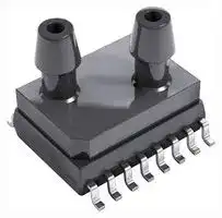
Pressure Sensor, SMI, 250 Pa, I2C Digital, Gauge, 5 V, Dual Axial, 3.3 mA
- Manufacturer: TE CONNECTIVITY
- Product type: Pressure Transducers
- Port Style: Dual Axial
- Product Range: SM9233 Series
- Sensor Output: I2C Digital
- Supply Current: 3.3mA
- Voltage Rating: 5V
- Operating Pressure Max: 250Pa
- Pressure Measurement Type: Gauge
| Delivery and price | |
|---|---|
| Units per pack | 20 |
| Price | 32.49 € |
| Current stock | 200+ |
| Lead time | 7 days |
te.com

## SMI ULTRA-LOW PRESSURE DIGITAL SENSOR

## SM9233/SM9235/SM9236/ SM9333/SM9336 Series

## Gage & Differential Pressure Sensors

The SM9000 series are digital, ultra-low pressure sensors offering state-of-the-art MEMS pressure transducer technology and CMOS mixed signal processing technology to produce a digital, fully conditioned, multi-order pressure and temperature compensated sensor in JEDEC standard SOIC-16 package with a dual vertical porting option (dual horizontal porting available for selected configurations). It is available in a gage and a differential pressure configuration.

The total error band after board mount and system level autozero is less than 1%FS. The warmup behavior and long-term stability further confirms its expected performance over the life of the part.

## Features

- Pressure ranges:

   - 125 and 250 Pa Differential

   - 250 up to 600 Pa Gage

- Total error band after Autozero: < 1%FS

- 16-bit I[2] C Digital interface

- Pressure calibrated and temperature compensated output

Combining the pressure sensor with a signal-conditioning ASIC in a single package simplifies the use of advanced silicon micro-machined pressure sensors.  The pressure sensor can be mounted directly on a standard printed circuit board and a high level, calibrated pressure signal can be acquired from the digital interface.  This eliminates the need for additional circuitry, such as a compensation network or microcontroller containing a custom correction algorithm.

The SM9233/SM9235/SM9236/SM9333/SM9336 are shipped in sticks or tape & reel.

- Compensated temperature range: -20 to 85[o] C

## Applications

- CPAP / Sleep Apnea

- Ventilator

- Gas Flow Instrumentation

- Air Flow Measurement

- HVAC / VAV

- Pressure Transmitter

- Pressure Switches

- Pneumatic Gauges

- Safety Cabinets

Page 1

TE CONNECTIVITY SENSORS /// SM9233/SM9235/SM9236/SM9333/SM9336 SERIES                                      08/2020

ULTRA-LOW PRESSURE DIGITAL SENSOR

SM9233/SM9235/SM9236/SM9333/SM9336 Series

## Performance Specifications

## 1.  Absolute Maximum Ratings

**All parameters are specified at VDD = 3.3 V supply voltage at 25°C, unless otherwise noted.**

|**Characteristic**|**Symbol**|**Min**|**Max**|**Units**|
|---|---|---|---|---|
|Supply Voltage|VDD|3.0|5.5|V|
|Digital IO Voltage|VIO,DIG|-0.3|VDD+0.3|V|
|Max. Digital IO Current (DC)|IIO,DIG|-10|+10|mA|
|Storage Temperature(a,b)|TSTG|-40|+125|°C|
|Proof Pressure(a, c)|PProof|7 (1.0)||kPa (PSI)|
|Burst Pressure(a, d)|PBurst|20 (2.9)||kPa (PSI)|


**Notes** :

- a) Tested on a sample basis.

- b) Clean, dry air compatible with wetted materials. Wetted materials include silicon, glass, RTV (silicone), gold, aluminum, copper, nickel, palladium, epoxy, stainless steel and plastic (mold compound).

- c) Proof pressure is defined as the maximum pressure to which the device can be taken and still perform within specifications after returning to the operating pressure range.

- d) Burst pressure is the pressure at which the device suffers catastrophic failure resulting in pressure loss through the device.

## 2.  ESD

|**Description**|**Symbol**|**Min**|**Max**|**Units**|
|---|---|---|---|---|
|ESD HBM Protection at all Pins|VESD(HBM)|-2|2|kV|


## 3.  External Components

|**Description**|**Symbol**|**Min**|**Typ**|**Max**|**Units**|
|---|---|---|---|---|---|
|Supplybypass capacitor*|CVDD||100||nF|
|I2C Data and clockpull upresistors*|RP||4.7||kOhm|


* Not tested in production

## 4.  Calibrated Pressure Ranges

|**Device Type **|PMIN (Pa)|PMAX (Pa)|
|---|---|---|
|SM9233 – 250 Gage|0|+250|
|SM9235 – 300 Gage|0|+300|
|SM9236 – 600 Gage|0|+600|
|SM9333 – 125 Differential|-125|+125|
|SM9336 – 250 Differential|-250|+250|


TE CONNECTIVITY SENSORS /// SM9233/SM9235/SM9236/SM9333/SM9336 SERIES                                      08/2020

Page 2

## ULTRA-LOW PRESSURE DIGITAL SENSOR

SM9233/SM9235/SM9236/SM9333/SM9336 Series

## 5.  Recommended Operating Conditions

**The recommended operating conditions must not be exceeded in order to provide proper functionality of the device. All parameters specified in the following sections refer to these recommended operating conditions unless stated otherwise.**

|**Description**|**Symbol**|**Min**|**Typ**|**Max**|**Max**|**Units**|
|---|---|---|---|---|---|---|
|Supply Voltage|VVDD|3.0|3.3|5.5|SM9233/SM9235/SM9236|V|
|||||3.6|SM9333/SM9336||
|Low level input voltage at SDA,SCL|VIN,I2C,lo|-0.3||0.9||V|
|High level input voltage at SDA,SCL|VIN,I2C,hi|0.8 * VVDD||VVDD+0.3||V|
|Compensated Temperature(b)|TCOMP|-20||+85||°C|
|OperatingTemperature|TA|-20||85||°C|


## **Notes:**

a) Clean, dry air compatible with wetted materials.

## 6.  Operating Characteristics Table

**All parameters are specified at Vdd = 3.3 V or 5 V DC supply voltage (as per PART NUMBER in table 9 (ORDERING INFORMATION)) at 25 oC, unless otherwise noted.**

|**Characteristic**|**Series**|**Symbol**|**Min**|**Typ**|**Max**|**Units**|
|---|---|---|---|---|---|---|
|Supply Current at 3.3V<br>(e)|SM9233/SM9235/SM9236|IVDD3p3||3.3|4.1|mA|
|Supply Current at 5.0V<br>(e)||IVDD5p0||3.9|5|mA|
|Supply Current at 3.3V<br>(e)|SM9333/SM9336|IVDD3p3||3.3|3.8|mA|
|Supply Current at 5.0V<br>(e)||IVDD5p0||3.9|5|mA|
|Digital Pressure Output<br>@PMIN|All|OUTMIN||-26,215||Counts|
|Digital Pressure Output<br>@PMAX|All|OUTMAX||+26,214||Counts|
|Digital Full Scale Span|All|FS||52,429||Counts|
|Resolution (Digital Output)|All|||16||Bits|
|Update Rate|All|||2000||Hz|
|Digital Output Total Error Band<br>after Autozero(f, g, h)|SM9233|ACCAZ|-1.25|± 0.25|1.25|%FS|
||SM9235||-1|±0.2|1|%FS|
||SM9236||-1|± 0.1|1|%FS|
||SM9333||-1.25|0.2|1.25|%FS|
||SM9336||-1|0.1|1|%FS|
|Digital Output Total Error Band<br>(f)|SM9233|ACC|-2.75|± 0.5|2.75|%FS|
||SM9235||-2.3|±0.4|2.3||
||SM9236||-1.25|± 0.3|1.25|%FS|
||SM9333||-2.75|± 0.5|2.75|%FS|
||SM9336||-1.5|± 0.3|1.5|%FS|
|Bandwidth|All|BW||20||Hz|
|PositionSensitivity|All|SG||0.1||%FS/g|
|Power-up time*|From supply VDD > 3.0 V to output<br>settled to 63% of final value|tUP||18||ms|
|Step response time*|Pressure step response; settled to<br>63% of final value|tRESP||18||ms|
|Step response settling time*|Pressure step response; output<br>settled to full total error band|tSETTLE||45||ms|


* Not tested in production

## **Notes** :

- e) Supply current given for continuous operation.  Device can be set to sleep mode with significantly lower power consumption. Refer to section 11 for details.

- f) The total error band specification applies overall operating conditions in dry clean air. This specification includes the combination of linearity, repeatability, and hysteresis errors over pressure, temperature, and 3.3 V supply voltage.

- g) Based autozero calibration at 25 °C after board mount or solder reflow. Autozero can be performed by the user in user software by storing the offset reading at zero differential (or gage) pressure and subtracting this stored reference offset value from actual readings when in use.on system level autozero at 25 °C after board mount or solder reflow.

- h) Based on sample testing during initial product qualification, not tested in production

TE CONNECTIVITY SENSORS /// SM9233/SM9235/SM9236/SM9333/SM9336 SERIES                                      08/2020

Page 3

## ULTRA-LOW PRESSURE DIGITAL SENSOR

SM9233/SM9235/SM9236/SM9333/SM9336 Series

## 7.  I[2] C Interface

|**Description**|**Condition**|**Symbol**|**Min**|**Typ**|**Max**|**Units**|
|---|---|---|---|---|---|---|
|SDA output low voltage*|ISDA= 3 mA|VSDA,OL|0||0.4|V|
|Low-to-High transition threshold*|pins SA0,SCL|VSDA,LH|0.5|0.6|0.7|VDD|
|High-to-Low transition threshold*|pins SA0,SCL|VSDA,HL|0.3|0.4|0.5|VDD|
|I2C clock frequency*||fSCL|||400|kHz|
|Bus free time between a START and STOP condition*||tBUSF|1300|||ns<br>||
|Clock low time*||tLO|1300|||ns|
|Clock high time*||tHI|600|||ns|
|START condition hold time*||tSH|100|||ns|
|Data setuptime*||tSU|100|||ns|
|Data hold time*|||tH<br>|<br>~~ee~~|0<br>~~ee~~|~~ee~~||ns<br>~~|~~|
|Setuptime for repeated START condition*|||tRSH<br>|<br>~~ee~~|600<br>~~ee~~|~~ee~~||ns<br>~~|~~|
|Setuptime for STOP condition*|||tPSU<br>|<br>~~ee~~|600<br>~~ee ~~|~~ee~~||ns<br>~~|~~|
|Rise time of SDA and SCL signals*||tR|||300|ns|
|Fall time of SDA and SCL signals*<br>~~PT~~|~~PT~~<br>~~|~~|tF<br>~~|~~<br>~~es~~|~~es~~|~~es~~|300<br>~~es~~|ns<br>~~es~~|


* Not tested in production

## 8.  Package Reference

**SOIC-16 (C) Vertical Package Dimensions**

**Lot number identification on top side**

TE CONNECTIVITY SENSORS /// SM9233/SM9235/SM9236/SM9333/SM9336 SERIES                                      08/2020

Page 4

ULTRA-LOW PRESSURE DIGITAL SENSOR

SM9233/SM9235/SM9236/SM9333/SM9336 Series

## **SOIC-16 (C) Vertical Package Dimensions**

**Lot number identification on top side**

## **Notes** :

- All dimensions in units of [mm]

- Moisture Sensitivity Level (MSL): Level 3

- Clean, dry air compatible with wetted materials. Wetted materials include : Wetted materials include silicon, glass, RTV (silicone), gold, aluminum, copper, epoxy and mold compound.

- Tolerance on all dimensions ±0.13 mm unless otherwise specified.

- [B] is tube connected to bottom side of sensor die.

- [T] is tube connected to top side of sensor die. Topside pressure is positive pressure. An increase in topside pressure will result in an  increase in sensor output

- Bottom plate is stainless steel

- Electrically isolate the bottom metal cover, do not connect to the cover and keep the board underneath free from electrical circuits.

- Robust JEDEC SOIC-16 package for automated assembly

- Manufactured according to ISO9001 , ISO14001 and ISO/TS 16949 standards

TE CONNECTIVITY SENSORS /// SM9233/SM9235/SM9236/SM9333/SM9336 SERIES                                      08/2020

Page 5

ULTRA-LOW PRESSURE DIGITAL SENSOR SM9233/SM9235/SM9236/SM9333/SM9336 Series

**Applications Circuit SM9233/SM9235/SM9236/SM9333/SM9336**

## **Package Labeling**

|**Pin No**|**Pin Function**|
|---|---|
|1|NC (No Connect)|
|2|NC|
|3|NC|
|4|NC|
|5|VSS|
|6|VDD|
|7|NC|
|8|NC|
|9|NC|
|10|SDA|
|11|SCL|
|12|NC|
|13|GND(ASICTestPin)|
|14|NC|
|15|NC|
|16|NC|


## **Notes** :

- Do not connect to NC pins

TE CONNECTIVITY SENSORS /// SM9233/SM9235/SM9236/SM9333/SM9336 SERIES                                      08/2020

Page 6

ULTRA-LOW PRESSURE DIGITAL SENSOR

SM9233/SM9235/SM9236/SM9333/SM9336 Series

## 9.  Ordering Information (Standard Configurations)

|**Part Number**|**Pressure Range**|**Voltage**|**Shipping(a)**|**Package**<br>**Configuration**|**Comment**|
|---|---|---|---|---|---|
|SM9233-BCE-S-250-000|0 to +250 Pa|3.3 V|Sticks (45<br>parts/stick)|SOIC-16 Dual<br>Vertical|Bandwidth<br>20Hz(b)|
|SM9235-BCE-S-300-000|0 to +300 Pa|||||
|SM9235-BBE-S-300-000|0 to +300 Pa|||SOIC-16 Dual<br>Horizontal||
|SM9236-BCE-S-600-000|0 to +600 Pa|||SOIC-16 Dual<br>Vertical||
|SM9233-BCE-S-250-002|0 to +250 Pa|5.0 V||||
|SM9235-BCE-S-300-002|0 to +300 Pa|||||
|SM9236-BCE-S-600-002|0 to +600 Pa|||||
|SM9333-BCE-S-125-000|-125 Pa to +125 Pa|3.3 V||||
|SM9336-BCE-S-250-000|-250 Pa to +250 Pa|||||
|SM9333-BBE-S-125-000|-125 Pa to +125 Pa|||SOIC-16 Dual<br>Horizontal||
|SM9333-BBE-S-250-000|-250 Pa to +250 Pa|||||


**Notes** :

- a) All parts also available in shipping configuration Tape & Reel (SOIC-16 Dual Horizontal 500 parts/reel; SOIC-16 Dual Vertical 350 parts/reel), see section 10. Part Numbering Key for ordering information

- b) Contact us for bandwidths other than 20 Hz

TE CONNECTIVITY SENSORS /// SM9233/SM9235/SM9236/SM9333/SM9336 SERIES                                      08/2020

Page 7

ULTRA-LOW PRESSURE DIGITAL SENSOR

SM9233/SM9235/SM9236/SM9333/SM9336 Series

## 10.  Part numbering key

**==> picture [493 x 339] intentionally omitted <==**

**----- Start of picture text -----**<br>
Part Number<br>SM – XXXX XXX X XXX 0 0 0<br>Max Pressure Range<br>9  +125 to +600 Pa<br>Counter<br>Pressure Range<br>Pressure Type<br>2  Gage<br>Shipping Format<br>3  Differential<br>S  Stick<br>T  Tape & Reel<br>Output Type<br>3  16-bit I [2] C<br>Compensated Temperature Range<br>Total Error Band<br>E  -20 to +85 °C<br>3  3% FS (before Autozero)<br>5  2.5% FS (before Autozero)<br>6  1.5% FS (before Autozero)  Package Type and Porting<br>BC  SOIC-16 w/ dual vertical porting<br>BB  SOIC-16 w/ dual horizontal porting<br>**----- End of picture text -----**<br>


TE CONNECTIVITY SENSORS /// SM9233/SM9235/SM9236/SM9333/SM9336 SERIES                                      08/2020

Page 8

ULTRA-LOW PRESSURE DIGITAL SENSOR

SM9233/SM9235/SM9236/SM9333/SM9336 Series

## 11.  Typical Characteristics (SM9233/SM9235/SM9236)

**==> picture [262 x 424] intentionally omitted <==**

**----- Start of picture text -----**<br>
400<br>350<br>& 300 g§<br>3250 3<br>é 200 &<br>150<br>100<br>50<br>0<br>ona NmMtTH OR AAA ANaMTt<br>oo o0o00000 0 aA aA nA a et<br>Absolute Total Error Band (%FS)<br>SM923x Absolute Accuracy after<br>Boardmount and Autozero - Histogram<br>25<br>—<br>n<br>20 RSuw<br>€<br>5 45 5<br>ia<br>S §<br>2 10 x<br>a 2<br>fir]<br>5 B<br>e<br>0)<br>SCH NM tT HOR AAAANM Tt<br>oo oo9ocvmUcmUmpUmUmUcUUCOOUULUCO aA a aA aA a<br>Absolute Accuracy (%FS)<br>SM923x Zero Pressure Accuracy’ at 30 °C vs. Hours<br>at 105 °C and 5.5V, 3 lots, 105 parts<br>1.00<br>0.80<br>0.60 | sse<br>— ——— 35<br>—as<br>ma —avgeas a<br>**----- End of picture text -----**<br>


TE CONNECTIVITY SENSORS /// SM9233/SM9235/SM9236/SM9333/SM9336 SERIES                                      08/2020

Page 9

ULTRA-LOW PRESSURE DIGITAL SENSOR SM9233/SM9235/SM9236/SM9333/SM9336 Series

## 11.  Typical Characteristics (SM9333/SM9336)

**==> picture [14 x 99] intentionally omitted <==**

**----- Start of picture text -----**<br>
1.00<br>0.80<br>0.60<br>0.40<br> -0,20<br>5.60<br>**----- End of picture text -----**<br>


- Zero pressure total error band tested at 30 oC and 3.3V. Measured after HTOL (at 105 oC and 5.5V) at 168, 500 and 1000 hrs. Not tested in production

TE CONNECTIVITY SENSORS /// SM9233/SM9235/SM9236/SM9333/SM9336 SERIES                                      08/2020

Page 10

ULTRA-LOW PRESSURE DIGITAL SENSOR

SM9233/SM9235/SM9236/SM9333/SM9336 Series

## 12.  Functional Description

## 12.1  Overview

The SM9000 series is a high precision, factory calibrated pressure sensor for ultra-low pressure measurements. It combines a low pressure MEMS die with a 16 bit ASIC, utilizing DSP for multi dimensional polynomial error correction. The calibrated pressure output data is available 2 via digital data interface (I C).  Status information on the sensor integrity and unique serial number are accessible via this digital interface.

## 12.2  Global Sensor Parameters

## 12.2.1  Digital Pressure Transfer Function

In general digital output data is available with a word length of 16 bit. The numeric representation is always as 2's complement, which results in a range of:

0 ... +32767 counts (positive range, or 0000h ... 7FFFh)

-32768 ... -1 counts (negative range, or 8000h ... FFFFh)

The pressure sensor device is calibrated in the end-of-line production test over the specified Pmin to Pmax pressure range (see Section 4). The output code at Pmin is  nominally -26,215 and at  Pmax it is nominally 26,214. This allows the sensor to still operate monotically outside its nominal range till the maximum (or minimum) counts are reached.

**An example for a 250 Gauge SM9233-BCE-S-250-000 is given in the graph below**

**An example for a 250 differential SM9336-BCE-S-250-000 is given in the graph below**

TE CONNECTIVITY SENSORS /// SM9233/SM9235/SM9236/SM9333/SM9336 SERIES                                      08/2020

Page 11

ULTRA-LOW PRESSURE DIGITAL SENSOR

SM9233/SM9235/SM9236/SM9333/SM9336 Series

**An example for a 250 differential SM9336-BCE-S-250-000 is given in the graph below**

**Green:** Total error band per specification

**Red** and **Blue** :  Outside specification, but expect monotonic behavior till maximum (or minimum) code is reached

## 12.2.2  Conversion from counts to pressure

The digital output count gives a signed 16 bit value for pressure and to convert the count reading OUTread to actual calibrated pressure units pp-unit  the following equation can be used

+

with pmin, pmax, OUTmin and OUTmax as specified in sections 4 and 6.

## 12.2.4  Digital Temperature Transfer Function

An internal temperature sensor measures the chip temperature. The temperature characteristic is linear and is described by the following equation:

DT = b1 * TA + b0

**The temperature transfer function parameters are as follows:**

|**Temperature**|**Temperature**|**Digital Output**|**Digital Output**|**Sensitivity / Offset**|**Sensitivity / Offset**|**Sensitivity / Offset**|
|---|---|---|---|---|---|---|
|**Symbol**|**Temperature[°C]**|**Symbol**|**Value[counts]**|**Symbol**|**Value**|**Unit**|
|TA,1|-40|DT,OUT,1|-32768|b1|397.2|counts/°C|
|TA,2|125|DT,OUT,2|32767|b0|-16881|counts|


The typical temperature accuracy at 30 °C is within  ± 2 °C.

## 12.3  Voltage Supply

The device is supplied from pin VDD, typically 3.3 V, but it can operate as high as 5 V. From this supply input several internal voltage regulators are generating stabilized voltage levels for analog and digital circuit sections. The different internal voltages are monitored by power-OK diagnostic circuitry. Also a stabilized voltage for the resistive MEMS pressure sensor is derived from VDD.

The digital data interface allows to set it into Sleep Mode using a specific command (Enter Sleep Mode), which confirms very low consumption (IVDD,SM) of typically less than 10 µA. Of course, in Sleep Mode no pressure data is acquired.

TE CONNECTIVITY SENSORS /// SM9233/SM9235/SM9236/SM9333/SM9336 SERIES                                      08/2020

Page 12

ULTRA-LOW PRESSURE DIGITAL SENSOR

SM9233/SM9235/SM9236/SM9333/SM9336 Series

For the I[2] C command to send the sensor into Sleep Mode see 13.6. To wake-up the sensor to normal operation, the clock input SCL shall be toggled (a rising edge at SCL will wake-up the device).

## 12.4  Diagnosis Functions

## 12.4.1  MEMS Sensor Bridge Diagnostics

Internal errors of the MEMS pressure sensor are detected and the STATUS registers can be read via the digital I[2] C interface.

## **Bridge Diagnostics**

An integrated bridge diagnostic circuit supervises the resistive pressure sensor to detect any of the faults as follows:

- Sensor faults:

   - Short of any of the four bridge resistors of the pressure sensor

   - Interruption of any of the four of bridge resistors

- Wiring faults:

   - Open connection of any of the bridge supply or signals

   - Wrong connection of any sensor bridge terminal to either ground or bridge supply

The MEMS sensor bridge diagnostics are active permanently (true background diagnostics) and in case of an error the bridge check fail event is indicated by setting the bit bc_fail in the internal STATUS register.

## **Bridge Supply Diagnostics**

Another diagnostic function checks if the supply to the sensor bridge is in its specified range. Here, in case of a supply error the bit bs_fail in the STATUS register will be set.

## 12.4.2  Configuration Memory Check

The integrity of data stored in the embedded NVM used as the configuration memory (calibration parameters, device configuration, device ID, etc.) is checked at power-up of the component by calculation of a check sum (CRC). If a check sum error is detected no reliable pressure calculation is possible.

Therefore, the sensor remains in idle state, i.e. no pressure data transferred to the output registers DSP_T and DSP_S. In this case the bits STATUS.dsp_s_up and dsp_t_up will never be set.

## 12.5  I[2] C Interface

The SM9xxx features an I[2] C slave interface. This interface provides direct access to registers of the memory of the SM9xxx sensor. An external I[2] C master (e.g. a microcontroller) can read from and write to memory addresses (registers) of the device using the following commands:

- **Random write:** Sets a memory address and writes data to consecutive memory addresses of the device starting at the set memory address.

- **Random read:** Sets a memory address and reads data from consecutive memory addresses of the device starting at the set memory address.

- **Read last:** Reads data from the device starting at the last memory address set by the master. This facilitates repeated reading of the same memory addresses without transmitting a memory address first.

All reads/writes must start at word aligned addresses (i.e. LSB of memory address equals 0) and read/write an even number of bytes.

TE CONNECTIVITY SENSORS /// SM9233/SM9235/SM9236/SM9333/SM9336 SERIES                                      08/2020

Page 13

ULTRA-LOW PRESSURE DIGITAL SENSOR

SM9233/SM9235/SM9236/SM9333/SM9336 Series

I[2] C Interface Timing Diagram:

## 12.5.1  I[2] C Command Format

The SM9x3x-Sensor uses a standard 7-bit I[2] C slave address field. The LSB of the slave address specifies the frame type used to perform read and write operations.

For LSB = 0 the protocol is compatible to standard I[2] C EEPROMs, for LSB = 1 the protocol is extended by a CRC protection. Thus, each device occupies two I[2] C addresses: even addresses are for standard EEPROM compatible protocols and odd addresses are for CRC protected protocols. Unprotected and CRC protected frames can be interleaved.

The two different frame types - standard EEPROM (without CRC) or CRC protected - are shown in the next two figures.

**I[2] C Read / Write Commands - Standard EEPROM compatible protocol**

TE CONNECTIVITY SENSORS /// SM9233/SM9235/SM9236/SM9333/SM9336 SERIES                                      08/2020

Page 14

ULTRA-LOW PRESSURE DIGITAL SENSOR

SM9233/SM9235/SM9236/SM9333/SM9336 Series

**I[2] C Read / Write Commands - CRC protected protocol**

The memory address field sets the byte address of the first memory location to be read from or written to. Only 16-bit-word aligned reads/writes are supported, i.e. the LSB of memory address has to be zero always. The read/write data is transferred MSB first, low byte before high byte.

The length field (bits[7:4]) required for CRC protected frames specifies the number of data bytes to be transferred decremented by one, i.e. a value of 0001b corresponds to two bytes. All frames must transfer an even number of bytes. The maximum length for CRC protected read/write frames is 16/4 bytes. For unprotected frames the length is unlimited.

The CRC4 and CRC8 for redundancy check are computed in the same bit and byte order as the transmission over the bus. The polynomials employed are:

- CRC4: polynomial 0x03; initialization value: 0x0F

- CRC8: polynomial 0xD5; initialization value: 0xFF

If a CRC errors occurs, then the event bit com_crc_error in the STATUS register will be set.

## 12.5.2  I[2] C Command Examples

For all examples below the 7-bit device slave address used is 0x6C for unprotected commands, and 0x6D for CRC protected commands, respectively.

The command sequence following describes an unprotected Read command (without CRC) of 3 subsequent 16-bit words starting at memory address 0x2E to read the corrected IC temperature, corrected pressure signal, and (synchronized) status bits of the sensor.

Random Read:

|**Byte #**|**0**|**1**|**2**|**3**|**4**|**5**|**6**|**7**|**8**|
|---|---|---|---|---|---|---|---|---|---|
|SBM<br>(sent by<br>master)|0xD8|0x2E|0xD9|||||||
|SBM<br>comment|slave<br>address 6C<br>+ LSB = 0<br>for_Write_|memory<br>address|slave<br>address 6C<br>+ LSB = 1<br>for_Read_|||||||
|SBS<br>(sent by<br>sensor)||||0xF2|0x7D|0xEA|0x82|0x1E|0x00|
|SBS<br>comment||||DSP_T<br>(Lo-Byte)<br>ad. 0x2E|DSP_T<br>(Hi-Byte)|DSP_S<br>(Lo-Byte)<br>ad. 0x30|DSP_S<br>(Hi-Byte)|sync‘ed<br>Status<br>(b7 - b0)<br>ad.0x32|sync‘ed<br>Status<br>(b15 - b8)|


TE CONNECTIVITY SENSORS /// SM9233/SM9235/SM9236/SM9333/SM9336 SERIES                                      08/2020

Page 15

ULTRA-LOW PRESSURE DIGITAL SENSOR

SM9233/SM9235/SM9236/SM9333/SM9336 Series

The following sequence writes one 16-bit word to address 0x22. This will copy 0x6C32 into the command register CMD to move the component to Sleep Mode.

## Random Write:

|**Byte #**|**0**|**1**|**2**|**3**|
|---|---|---|---|---|
|SBM<br>(sent bymaster)|0xD8|0x22|0x32|0x6C|
|SBM comment|slave address 6C<br>+ LSB = 0<br>for_Write_|memory address|Lo-Byte written to<br>CMD[7:0]|Hi-Byte written to<br>CMD[15:8]|
|SBS<br>(sent by sensor)|||||
|SBS comment|||||


The next command sequence describes a CRC protected Read command of 3 subsequent 16-bit words starting at memory address 0x2E. Random Read - protected by CRC:

|**Byte #**|**0**|**1**|**2**|**3**|**4**|**5**|**6**|**7**|**8**|**9**|**10**|
|---|---|---|---|---|---|---|---|---|---|---|---|
|SBM<br>(sent by<br>master)|0xDA|0x2E|0x5B|0xDB||||||||
|SBM<br>comment|slave<br>address<br>6D<br>+ LSB = 0<br>for_Write_|memory<br>address|3:<br>length =<br>4Byte<br>B:<br>CRC4|slave<br>address<br>6D<br>+ LSB =<br>1<br>for_Read_||||||||
|SBS<br>(sent by<br>sensor)|||||0xF2|0x7D|0xEA|0x82|0x1E|0x00|0x65|
|SBS<br>comment|||||DSP_T<br>(Lo-<br>Byte)<br>ad.<br>0x2E|DSP_T<br>(Hi-<br>Byte)|DSP_S<br>(Lo-<br>Byte)<br>ad.<br>0x30|<br>DSP_S<br>(Hi-<br>Byte)|sync‘ed<br>Status<br>(b7 - b0)<br>ad. 0x32|sync‘ed<br>Status<br>(b15 -<br>b8)|CRC8<br>(calc'd)|


The next example describes a Write of one 16-bit word (contents 0xCF9E) with CRC protection to address 0x36 to clear events in the STATUS register.

Random Write - protected with CRC:

|**Byte #**|**0**|**1**|**2**|**3**|**4**|**5**|
|---|---|---|---|---|---|---|
|SBM<br>(sent bymaster)|0xDA|0x36|0x16|0x9E|0xCF|0xA1|
|SBM comment|slave address 6D<br>+ LSB = 0<br>for_Write_|memory address|1: length = 2Byte<br>6: CRC4|STATUS<br>(Lo-Byte)<br>ad.0x36|STATUS<br>(Hi-Byte)|CRC8<br>(calculated)|
|SBS<br>(sent by sensor)|||||||
|SBS comment|||||||


TE CONNECTIVITY SENSORS /// SM9233/SM9235/SM9236/SM9333/SM9336 SERIES                                      08/2020

Page 16

ULTRA-LOW PRESSURE DIGITAL SENSOR

SM9233/SM9235/SM9236/SM9333/SM9336 Series

## 12.6  Register Descriptions

Register Read or Write are performed via the digital communication interface. After power-up of the IC all registers except STATUS and CMD are write protected.

## Command register:

|**0x22**|**CMD**||||
|---|---|---|---|---|
|**bits**|**name**|**default**|**rw**|**description**|
|15:0|cmd|0|w|Writing to this register controls the state of the SM9x3x device.|
|||||0x6C32: SLEEP Mode<br>Initiate the power state SLEEP, powering down the ASIC|
|||||0xB169: RESET<br>Performs a reset. After reset the power-up sequence will be executed, i.e. the registers are loaded with<br>data from the configuration memory, also a CRC check is performed.|


Temperature register:

|**0x2E**|**DSP_T**||||
|---|---|---|---|---|
|**bits**|**name**|**default**|**rw**|**description**|
|15:0|dsp_t||r|Corrected temperature measurement value of the sensor.<br>Whenever this register is updated with a new measurement the STATUS.dsp_t_upevent bit is set.|


## Pressure register:

|**0x30**|**DSP_S**||||
|---|---|---|---|---|
|**bits**|**name**|**default**|**rw**|**description**|
|15:0|dsp_s||r|Corrected pressure measurement value of the sensor.<br>Whenever this register is updated with a new measurement the STATUS.dsp_s_upevent bit is set.|


The registers DSP_T and DSP_S contain invalid data after power-up until the first temperature and pressure values have been measured by the device and transferred to these registers. In case a NVM CRC error occurred, the DSP_T and DSP_S registers would never be updated. Thus, after power up it is necessary to wait until the STATUS.dsp_s_up and dsp_t_up bits have been set at least once before using the temperature or pressure data. It is not sufficient to wait just for a fixed time delay _**.**_

Status register - synchronized:

|**0x32**|**STATUS_SYNC**|||||
|---|---|---|---|---|---|
|**bits**|**name**|**default**|**rw**|**type**|**description **|
|0|idle|0|rw|status|STATUS.idle|
|1|- reserved -|0|rw|event|reserved|
|2|- reserved -|0|rw|event|reserved|
|3|dsp_s_up|0|rw|event|when DSP_S is read STATUS.dsp_s_upis copied here|
|4|dsp_t_up|0|rw|event|when DSP_T is read STATUS.dsp_t_upis copied here|
|5|- reserved -|0|rw|status|reserved|
|6|- reserved -|0|rw|status|reserved|
|7|bs_fail|0|rw|event|STATUS.bs_fail|
|8|bc_fail|0|rw|event|STATUS.bc_fail|
|9|- reserved -|0|rw|event|reserved|
|10|dsp_sat|0|rw|status|STATUS.dsp_sat|
|11|com_crc_error|0|rw|event|STATUS.com_crc_error|
|12|- reserved -|0|rw|status|reserved|
|13|- reserved -|0|rw|status|reserved|
|14|dsp_s_missed|0|rw|event|STATUS.dsp_s_missed|
|15|dsp_t_missed|0|rw|event|STATUS.dsp_t_missed|


TE CONNECTIVITY SENSORS /// SM9233/SM9235/SM9236/SM9333/SM9336 SERIES                                      08/2020

Page 17

ULTRA-LOW PRESSURE DIGITAL SENSOR

SM9233/SM9235/SM9236/SM9333/SM9336 Series

The bits STATUS_SYNC[15:5,0] are identical to the bits STATUS[15:5,0].

The bits STATUS_SYNC[4:3] are copied from the STATUS register when the corresponding DSP registers are read. First reading the DSP registers and then STATUS_SYNC confirms that both values are consistent to each other.

The synchronized status STATUS_SYNC register can be used to continuously poll the pressure, temperature and status of the device with a single read command by reading three 16 bit words starting at address 0x2E. By evaluating STATUS_SYNC.dsp_t_up and STATUS_SYNC.dsp_s_up it can be determined if the values in DSP_T and DSP_S acquired during the same read contain recently updated temperature or pressure values.

## Status register:

|**0x36**|**STATUS**|||||
|---|---|---|---|---|---|
|**bits**|**name**|**default**|**rw**|**type1**|**description **|
|0|idle|0|rw|status|0: chip in busy state<br>1:chipin idle state|
|1|- reserved -|0|rw|event|reserved|
|2|- reserved -|0|rw|event|reserved|
|3|dsp_s_up|0|rw|event|1: DSP_S register has been updated.<br>Clearedwhen DSP_Sisread|
|4|dsp_t_up|0|rw|event|1: DSP_T register has been updated.<br>Clearedwhen DSP_T isread.|
|5|- reserved -|0|rw|status|reserved|
|6|- reserved -|0|rw|status|reserved|
|7|bs_fail|0|rw|event|1: bridge supplyfailure occurred|
|8|bc_fail|0|rw|event|1: sensor bridge check failure occurred|
|9|- reserved -|0|rw|event|reserved|
|10|dsp_sat|0|rw|status|1:a DSP computataion leading to current DSP_T or DSP_S values was saturated to<br>prevent overflow|
|11|com_crc_error|0|rw|event|1:communication CRC error|
|12|- reserved -|0|rw|status|reserved|
|13|- reserved -|0|rw|status|reserved|
|14|dsp_s_missed|0|rw|event|1:dsp_s_up was 1 when DSP_S updated|
|15|dsp_t_missed|0|rw|event|1:dsp_t_upwas 1 when DSP_T updated|


- "Event" type flags remain set until cleared by writing '1' to the respective bit position in STATUS register (not STATUS_SYNC). Writing 0xFFFF to the STATUS register will clear all event bits.

- "Status" type flag represents a condition of a hardware module of the IC and persists until the condition has disappeared.

## Serial Number register 0:

|**0x50**|**SER0**||||
|---|---|---|---|---|
|**bits**|**name**|**default**|**rw**|**description**|
|15:0|ser0||r|Serial number of the IC, Lo-Word|


## Serial Number register 1:

|**0x52**|**SER1**||||
|---|---|---|---|---|
|**bits**|**name**|**default**|**rw**|<br>**description**|
|15:0|ser1||r|<br>Serial number of the IC, Hi-Word|


TE CONNECTIVITY SENSORS /// SM9233/SM9235/SM9236/SM9333/SM9336 SERIES                                      08/2020

Page 18

ULTRA-LOW PRESSURE DIGITAL SENSOR SM9233/SM9235/SM9236/SM9333/SM9336 Series

## 13.  Qualification Standards

REACH Compliant RoHS Compliant PFOS/PFOA Compliant For qualification specifications

## **GLOBAL**

Tel +1 408 577 0100 customercare.mlpt@te.com

## **te.com/sensors**

TE Connectivity, TE, TE Connectivity (logo) and Every Connection Counts are trademarks. All other logos, products and/or company names referred to herein might be trademarks of their respective owners

The information given herein, including drawings, illustrations and schematics which are intended for illustration purposes only, is believed to be reliable. However, TE Connectivity makes no warranties as to its accuracy or completeness and disclaims any liability in connection with its use. TE Connectivity‘s obligations shall only be as set forth in TE Connectivity‘s Standard Terms and Conditions of Sale for this product and in no case will TE Connectivity be liable for any incidental, indirect or consequential damages arising out of the sale, resale, use or misuse of the product. Users of TE Connectivity products should make their own evaluation to determine the suitability of each such product for the specific application.

© 2020 TE Connectivity Corporation. All Rights Reserved.

**Version 08/2020**

TE CONNECTIVITY SENSORS /// SM9233/SM9235/SM9236/SM9333/SM9336 SERIES                                      08/2020

Page 19
Updated at February 9, 2023
TE Connectivity is a globally recognized engineering and manufacturing leader, specializing in highly reliable connectivity and sensing solutions. Renowned for innovation and durability, their components are engineered to perform in the most demanding environments, supporting critical advancements in industrial equipment, data communications, and automotive systems. Our extensive selection of TE Connectivity products is anchored by their industry-leading connector portfolio. We carry a comprehensive array of terminal blocks and accessories, including wire-to-board, pluggable, standard, and barrier configurations, alongside robust backplane connectors designed to ensure secure and efficient power and data transmission in complex circuit designs. Beyond physical connections, TE Connectivity is a premier manufacturer of precision sensors, antennas, and electromechanical switching components. Our inventory features a wide variety of RF antennas and highly accurate pressure, temperature, and force transducers. Additionally, we provide an expansive range of TE's dependable relays, encompassing automotive, power, and signal variants, alongside essential passive components like shielding gaskets and RF inductors to fully support your engineering requirements.
About Novapart
Novapart is a B2B electronic component broker specialising in stock shortages and cost reduction. We source hard-to-find parts and identify compliant alternatives across a catalogue of 410,000+ components from 500+ manufacturers.
Learn more →Stock Shortage Specialist
When a component is unavailable, discontinued or has an unacceptable lead time, we tap into our network of vetted European and Asian distributors to source what you need — without compromising on quality or traceability.
Request a quote →Compliant Alternatives
We identify pin-to-pin, electrically equivalent substitutes that meet the same certifications (RoHS, AEC-Q100, REACH) as your original specification — validated against datasheets, not just part numbers. Often at a lower cost.
BOM Analysis service →