
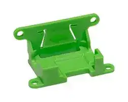


SLF3X MOUNTING CLAMP
Mounting Clamp, Liquid Flow Sensor
- Manufacturer: SENSIRION
- Product type:
- SVHC: No SVHC (12-Jan-2017)
- For Use With: Sensirion SLF3S-1300F Liquid Flow Sensor
- Accessory Type: Mounting Clamp
| Delivery and price | |
|---|---|
| Units per pack | 100 |
| Price | 2.92 € |
| Current stock | 10+ |
| Lead time | 15 days |
## **SLF3S-1300F Liquid Flow Sensor – PROTOTYPE** - Low flow sensing up to 40 ml/min - Calibrated and temperature compensated - Turn down ratio 200:1 or better - Very compact and light-weight form factor - Response time below 20 ms ## **Product Summary** The SLF3S-1300F is Sensirion’s new compact liquid flow sensor designed for high-volume applications. It enables precise and reliable measurements of dynamic liquid flow rates up to 40 ml/min bi-directionally. The SLF3S-1300F sensor features a digital interface (I[2] C) via a 6-pin standard electrical connector. The SLF3S-1300F builds on the latest generation CMOSens® sensor chip that is at the heart of Sensirion’s flow sensing platform and allows achieving an outstanding performance. The patented CMOSens® technology combines the sensor element, signal processing and digital calibration on a small CMOS chip. The well-proven CMOS technology is perfectly suited for high-quality mass production and is the ideal choice for demanding and cost-sensitive OEM applications. **The SLF3S-1300F sensor is still under development. Thus any specification is subject to change without prior notice (performance, communication, etc.).** ## **Benefits of Sensirion’s CMOSens[®] Technology** - High reliability and long-term stability - Best signal to noise ratio - Industry-proven technology with a track record of more than 15 years - Designed for mass production and high process capability 1/19 Preliminary version 04 – D1 – April 2019 www.sensirion.com ## **Contents** |**Contents**|| |---|---| |1 Sensor Performance (preliminary data, subject to change without prior notice)|3| |2 Specifications (preliminary data, subject to change without prior notice)|5| |3 Sensor Output Signal Description|6| |4 Digital Interface Description|9| |5 Fluidic Specifications and Connections|14| |6 Mechanical Specifications|14| |7 Mechanical Mounting of the SLF3S-1300F Sensor|15| |8 Ordering Information|17| |9 Tray Package|17| |10 Important Notices<br>11 Headquarters and Subsidiaries|18<br>19| **==> picture [301 x 290] intentionally omitted <==** 2/19 Preliminary version 04 – D1 – April 2019 www.sensirion.com ## **1 Sensor Performance** ## **(preliminary data, subject to change without prior notice)** The following Table 1 lists preliminary specifications of the current prototypes. Please contact Sensirion if different specifications are required. |Parameter|SLF3S-1300F|Unit|| |---|---|---|---| |H2O Full scale flow rate|40|ml/min|| |H2O Sensor output limit1|65|ml/min|| |Accuracy2<br>(whichever error is larger)|5<br>0.1|% of measured value<br>ml/min|| |Repeatability2<br>(whichever error is larger)|0.5<br>0.01|% of measured value<br>ml/min|| |Temperature coefficient3<br>(additional error / °C; whichever is larger)|tbd<br>tbd|% measured value / °C<br>% full scale / °C|| |Mountingorientation sensitivity4|tbd|% of full scale|| |Calibrated for|Water|-|| **Table 1:** Preliminary specifications for liquid flow sensor SLF3S-1300F (all data for medium H2O, at 23°C, and for VDD 3.5V) **==> picture [281 x 268] intentionally omitted <==** > 1 Flow rate at which the sensor output saturates. See section 1.1 for performance between full scale and saturation point. > 2 Accuracy respectively repeatability specifications valid for flow rates below ±20 ml/min. See the charts in section 2 for the accuracy and repeatability specifications, respectively, between ±20 ml/min and full scale. > 3 Additional accuracy error in case liquid and ambient temperatures are similar but both deviating from 23 °C. 4 Maximum additional offset when flow channel is vertical. 3/19 Preliminary version 04 – D1 – April 2019 www.sensirion.com ## **1.1 Specification Charts** The SLF3S-1300F liquid flow sensor shows bi-directional, linear transfer characteristics. The product comes fully calibrated for water. **Figure 1:** Liquid flow sensor accuracy and repeatability across the flow range of the SLF3S-1300F. Relative error in ±% of measured value for H2O. **Figure 2:** Liquid flow sensor accuracy and repeatability across the positive flow range of the SLF3S-1300F. Absolute error in ml/min for H2O. 4/19 Preliminary version 04 – D1 – April 2019 www.sensirion.com ## **2 Specifications (preliminary data, subject to change without prior notice)** ## **2.1 Electrical Specifications** ||Parameter|Symbol|Conditions|Min.|Typical|Max.|Units|Comments| |---|---|---|---|---|---|---|---|---| ||Supplyvoltage DC|VDD||3.2|3.5|3.8|V|| ||Power-up/down level|VPOR||2.3|2.5|2.7|V|| ||||Measurement||4.5|6|mA|| ||Supply current|IDD|Idle mode||0.05|0.6|mA|| ||||Sleepmode|||0.001|mA|| |**Table 2:**DC characteristics||||||||| ||**22Timing Specific**|**tions**||||||| |Parameter|Symbol|Conditions|Conditions|Conditions|Min.|Min.|Typical|Typical|Max.|Units|Comments| |---|---|---|---|---|---|---|---|---|---|---|---| |Supplyvoltage DC|VDD||||3.2||3.5||3.8|V|| |Power-up/down level|VPOR||||2.3||2.5||2.7|V|| |Supply current|IDD|Measurement|||||4.5||6|mA|| |||Idle mode|||||0.05||0.6|mA|| |||Sleepmode|||||||0.001|mA|| ||||||||||||| |**Table 2:**DC characteristics<br>**22Timing Specific**|**tions**||||||||||| |**. **|||||||||||| |Parameter|Symbol|Min.|Typical|Max.||Units||Comments|||| |Power-uptime|tPU|||25||ms||Time to sensor ready|||| |Soft reset time|tSR|||25||ms||Time between soft reset command or exit sleep mode and<br>sensor ready|||| |Warm-up time|tw||tbd|||ms||Time needed until sensor output is within specification<br>according to section 1.1 at 50% full scale flow rate.|||| |I2C SCL frequency|fI2C||400|1000||kHz|||||| |Update rate liquid flow<br>value and High Flow flag|fflow|1800|2000|2200||Hz|||||| |Update rate temperature<br>value and Air-in-Line flag|ftemp|73|83|111||Hz|||||| |Recommended sensor<br>read out frequency|fro|10|50-200|2000||Hz||Recommendations are based on explanations in section 3.1|||| **Table 3:** Timing specifications ## **2.3 Absolute Minimum and Maximum Ratings** |Parameter|Rating|Unit| |---|---|---| |Operatingtemperature|+5 … +50|°C| |Maximum relative humidity for long-term exposure|40°C dew point or 95 %RH, whichever is lower. non-<br>condensing|| |Short term storage temperature5|-40 … +60|°C| |Short term storage humidity5|0…95 %RH,non-condensing|% RH| |ESD HBM(human bodymodel)6|tbd|kV| |Maximum supplyvoltage|5.5|V| |||| **Table 4:** Absolute minimum and maximum ratings > 5 Flow path empty. Short term storage refers to temporary conditions during e.g. transport. > 6 ESD level of sensor chip. ESD level of entire system or device to be determined by customer. 5/19 Preliminary version 04 – D1 – April 2019 www.sensirion.com ## **2.4 Pad Assignment** The liquid flow sensor is equipped with a 6-pin connector (Molex Part Number: 53261-0671; 1.25 mm pitch PicoBlade header, surface mount, right angle, 6 circuits) for electrical connection, see below Table 5. |Pad|Description|Comments| |---|---|---| |1|n.c.|Nonfunctional, connect to GND or leave floating| |2|SDA(data)|Serial data, bidirectional| |3|VDD|Supply voltage| |4|GND|Ground| |5|SCL(clock)|Serial clock, bidirectional| |6|n.c.|Nonfunctional, connect to GND or leave floating| **Table 5:** Pin assignment ## **3 Sensor Output Signal Description** ## **3.1 Flow Rate Measurement** After the sensor receives the “start continuous measurement” command it enters the continuous measurement mode and continuously performs measurements of ~0.5 ms length. Therefore, the flow rate value is updated every 0.5 ms (see Table 3). The output flow rate value corresponds to the average 𝑥 of all individual 0.5 ms measurements 𝑥𝑖 since the last read out. This has the benefit that the user can read out the sensor at his own desired speed, without losing information and thus prevents aliasing. During the first 100 ms of averaging, the averaged value is obtained as the arithmetic mean. **==> picture [136 x 36] intentionally omitted <==** When the reading speed is slower than 100 ms, the sensor will continue to average, but with a different algorithm. In this algorithm exponential smoothing is used, with a smoothing factor 𝛼 = 0.0125. **==> picture [288 x 12] intentionally omitted <==** Where 𝑆0 is the arithmetic mean value after the first 100 ms and the output flow rate value corresponds to the last available 𝑆𝑘 . With an exponential smoothing factor of 𝛼 = 0.0125 the user receives approximately an average value of the last 100 ms. In order not to lose information the sensor should be read out at least once every 100 ms. Please refer to relevant literature for more information about exponential smoothing. When the sensor has entered exponential smoothing, this is indicated by bit 5 being set to high (=1) in the signaling flag output of the sensor (see section 3.3). ## **3.2 Temperature Measurement** The temperature is measured every ~12 ms (see Table 3) with the help of an additional onboard temperature sensor. It provides the chip’s temperature, which is influenced by the environmental, and the fluid’s temperature. The temperature values are not averaged as described above. The read out temperature value corresponds always to the latest temperature measurement available. 6/19 Preliminary version 04 – D1 – April 2019 www.sensirion.com ## **3.3 Extended Features for Failure Mode Detection** The SLF3S-1300F sensor uses Sensirion’s latest flow chip generation. This enables detecting failures like air-in-line or flow rates exceeding the output limit of the sensor. Such conditions are indicated as signaling flags to the user. In addition to the flow rate and temperature values, the user can therefore read out several signaling flags (see section 4.3.1), including two flags for failure mode detection as well as a flag indicating whether exponential smoothing is used as averaging algorithm of the flow rate data (see section 3.1). The two signaling flags for failure mode detection, the _Air-in-Line_ and the _High Flow flag_ , report if an air-in-line or high flow event occurred at least once since the last readout took place. I.e. if the sensor is read out again after 50 ms have passed, the signaling flags will be output as “high”, if an air-in-line or high flow condition was detected at least once at any time during the last 50 ms. When using Sensirion’s Viewer Software, the user has to select _Signaling Flags_ under the _Type of Measurement_ dropdown menu to display the signaling flags while taking measurements. An air-in-line condition is displayed as a “1” and a high flow condition is displayed as a “2”. If both conditions occur simultaneously this is hence displayed as “3”. The following sections provide further details about the two available failure mode detection signaling flags. ## **3.3.1 Detection of Air-in-Line** Owing to the thermal measurement principle of Sensirion’s liquid flow sensors, the sensors can differentiate between air and liquid media filling the flow channel. When air is passing through the sensor, bit 0 of the signaling flags is set to high (= 1). The bit 0 in the signaling flag output stays high until it is read out. See below. Since the air bubble has an impact on the flow velocity profile inside the sensor’s flow channel, the _High Flow flag_ (see below) might also be set at the beginning and at the end of the air bubble. The output of the signaling flags as well as the typically flow rate signal are visualized in the following graphs 1 to 5, while an air bubble travels through the sensor’s flow channel from left to right. 7/19 Preliminary version 04 – D1 – April 2019 www.sensirion.com ## **3.3.2 Detection of High Flow Rates** During priming or flushing of fluidic systems, much higher flow rates than the sensor’s output limit might be needed. The sensor is not damaged in these situations as long as the maximum recommended operating pressure is not exceeded. However, high flow rates (that exceed the output limit of the sensor) cause the sensor to saturate or output incorrect flow rate measurements. By checking the _High Flow_ flag this potential error can be monitored and detected reliably. In cases, where the output limit is exceeded, bit 1 of the signaling flags is set to high (= 1). The bit 1 in the signaling flag output stays high until it is read out. ## **3.4 Sensor Start-Up and Warm-Up Behavior** The maximum time for system power-up is 25 ms until the sensor responds to communication requests. After reset or start-up of the sensor, the sensor’s internal heater is turned off and must be started by performing a _Start Continuous Measurement_ command (see section 4.3.1). The very first measurement is delayed by approximately 12 ms for the SLF3S-1300F liquid flow sensor. Due to the thermal measurement principle, a total warm-up time (to be determined for SLF3S-1300F) is necessary for a reliable measurement. This includes the 12 ms needed for measurement initialization. **==> picture [455 x 131] intentionally omitted <==** **----- Start of picture text -----**<br> Reliable flow<br>Warm-up time (tbd)<br>measurement<br>Max power- Measurement Continuous measurements of<br>up time initialization ~0.5 ms length<br>/ /<br>Time 0 ms 25 ms X + 12 ms X + warm-up time<br>X: Start continuous<br>measurement<br>**----- End of picture text -----**<br> 8/19 Preliminary version 04 – D1 – April 2019 www.sensirion.com ## **4 Digital Interface Description** The sensor’s digital interface is compatible with the I[2] C protocol. This chapter describes the available command set. For detailed information about the I[2] C protocol, please consult the document "NXP I[2] C-bus specification and user manual" (http://www.nxp.com/documents/user_manual/UM10204.pdf). The physical interface consists of two bus lines, a data line (SDA) and a clock line (SCL) which need to be connected via pull-up resistors to the bus voltage of the system. ## **4.1 I[2] C Address** The sensor’s I[2] C address is 8. The I[2] C header is formed by the I[2] C address followed by a read or write bit. ## **4.2 I[2] C Sequences** The commands are 16-bit. Data is read from the sensor in multiples of 16-bit words, each followed by an 8-bit checksum to ensure communication reliability. I[2] C master sends the write header and writes a 16 bit command **==> picture [348 x 187] intentionally omitted <==** **----- Start of picture text -----**<br> I2CAdr[6:0] W Cmd[15:8] Cmd[7:0]<br>ie]Oe<br>C master sends the read header and receives multiple 16bit words with CRC byte.<br>I2CAdr[6:0] R Data1[15:8] Data1[7:0] CRC1[7:0]<br>Lo<br>or<br>a Data2[15:8] Data2[7:0] a CRC2[7:0] |= ||<br>i<br>or<br>≈<br>DataX[15:8] DataX[7:0] CRCX[7:0]<br>> | | *f<br>Start ACK ACK ACK<br>Start ACK ACK ACK Stop<br>(N)ACK<br>ACK ACK Stop<br>(N)ACK<br>ACK ACK NACK Stop<br>**----- End of picture text -----**<br> I[2] C master sends the read header and receives multiple 16bit words with CRC byte. Dark areas with white text indicate that the sensor controls the SDA (Data) line. I[2] C sequences can be aborted with a NACK and STOP condition. ## **4.3 I[2] C Commands** The command set consists of a set of different commands: - Start continuous measurement command - Stop measurement command - Soft reset - Entering and exiting sleep mode - Read product identifier and serial number 9/19 Preliminary version 04 – D1 – April 2019 www.sensirion.com ## **4.3.1 Start Continuous Measurement** The sensor measures both the flow rate and the temperature. Both measurement results can be read out through one single I[2] C read header while a continuous measurement is running. |Command|Command code (Hex)|Description| |---|---|---| |Start continuous<br>measurement|0x3608|This command starts the continuous measurement<br>mode. Outputs are the liquid flow rate, the chip’s<br>temperature and the signalingflags.| **Table 6:** I²C command to start continuous measurement After the command has been sent, the chip continuously measures and updates the measurement results as described in section 3. New results (flow and temperature) can be read continuously with a single I[2] C read header for each pair of measurements. After the start measurement command is sent: - the first measurement result is available after 12 ms; - small accuracy deviations (% m.v.) can occur while the sensor warms-up (see section 3.4). While no measurement data is available yet the sensor will respond with a NACK to the I[2] C read header (I[2] C address + read bit). |Preceding command|Consecutive read|Description| |---|---|---| |Continuous<br>measurement|Byte1: Flow 8msb<br>Byte2: Flow 8lsb<br>Byte3: CRC<br>Byte4: Temp 8msb<br>Byte5: Temp 8lsb<br>Byte6: CRC<br>Byte7: Signaling flags 8msb<br>Byte8: Signaling flags 8lsb<br>Byte9: CRC|After a start continuous measurement command, the<br>measurement results can be read out.<br>The temperature and the consecutive bytes don’t need<br>to be read out (every time). The read sequence can be<br>aborted by a NACK and a STOP condition.<br>Bit 0 and bit 1 of the signaling flags are used to detect<br>air-in-line and high flow events. Bit 5 of the signaling<br>flags indicates whether the sensor uses exponential<br>smoothing for flow data averaging. Bit 2 … 4 and 6 …<br>15 are reserved for future use.| **Table 7:** Consecutive reads after I²C command to start continuous measurement ||| |---|---| |Bit|Signaling flag (set to high=1, set to low=0)| |0|_Air-in-Line flag_| |1|_High Flow flag_| |2-4|_Unused, reserved for future use._| |5|_Exponential Smoothing active_| |6-15|_Unused, reserved for future use._| ||| **Table 8:** Bit assignment of 16 bit signaling flags 10/19 Preliminary version 04 – D1 – April 2019 www.sensirion.com ## **4.3.2 Stop Continuous Measurement** |Command|Command code (Hex)|Description| |---|---|---| |Stop continuous<br>measurement|0x3FF9|This command stops the continuous measurement and<br>puts the sensor in idle mode. After it receives the stop<br>command, the sensor needs up to 0.5 ms to power<br>down the heater, enter idle mode and be receptive for a<br>new command.| **Table 9:** I²C command to stop continuous measurement When the sensor is in continuous measurement mode, the sensor must be stopped before it can accept another command. The only exception is the soft reset command. In idle mode the sensor will consume less power, but consider the sleep mode for most effective energy saving. |**4.3.3 Soft Reset**|||| |---|---|---|---| |Command|I2C address + W bit +|Consecutive read|Description| ||command code (Hex)||| |General call reset|0x0006|NA|This sequence resets the sensor with a separate reset<br>block, which is as much as possible detached from the<br>rest of the system on chip.<br>Note that the I2C address is 0x00, which is the general call<br>address, and that the command is 8 bit.I.e., the soft reset<br>command must not be preceded by an I2C write header.<br>The reset is implemented according to the I2C<br>specification.| ||||| **Table 10:** Reset command After the reset command, the sensor will take maximum 25 ms to reset. During this time the sensor will not acknowledge its address nor accept commands. ## **4.3.4 Entering and Exiting Sleep Mode** In sleep mode, the sensor uses the minimum amount of current. The mode can only be entered from idle mode, i.e. when the sensor is not measuring. This mode is particularly useful for battery operated devices. To minimize the current in this mode, the complexity of the sleep mode circuit has been reduced as much as possible, which is mainly reflected by the way the sensor exits the sleep mode. In sleep mode the sensor cannot be soft reset. |Command|Command code (Hex)|Consecutive read|Description| |---|---|---|---| |Enter Sleep<br>mode|0x3677|NA|The sleep command can be sent after a stop continuous<br>measurement command has been issued and the sensor<br>is in idle mode.| |Exit Sleep<br>mode|NA|NA|The sensor exits the sleep mode and enters the idle mode<br>when it receives the**valid I2C address and a write bit**<br>**(‘0’).**<br>Note that the I2C address is**not**acknowledged. It is<br>necessary to poll the sensor to see whether the sensor<br>has received the address and has woken up. This should<br>take maximum 25 ms.| **Table 11:** Sleep mode commands 11/19 Preliminary version 04 – D1 – April 2019 www.sensirion.com ## **4.3.5 Read Product Identifier and Serial Number** The product identifier and serial number can be read out after sending a sequence of two commands. First the I[2] C master sends two consecutive write headers and writes 16 bits for each command. Then the I[2] C master sends the read header and receives 6 words of 16 bit with a CRC byte after each word. **==> picture [347 x 210] intentionally omitted <==** **----- Start of picture text -----**<br> I2CAdr[6:0] W Cmd1[15:8] Cmd1[7:0]<br>Co<br>I2CAdr[6:0] W Cmd2[15:8] Cmd2[7:0]<br>Snel<br>inl ee<br>I2CAdr[6:0] R Byte1 Byte2 CRC1[7:0]<br>i<br>a<br>Byte4 Byte5 CRC2[7:0]<br>a<br>rN<br>≈<br>Byte16 Byte17 CRC6[7:0]<br>Dark areas with white text indicate that the sensor controls the SDA (Data) line.<br>Start ACK ACK ACK<br>Start ACK ACK ACK<br>Start ACK ACK ACK ACK<br>ACK ACK ACK<br>ACK ACK ACK Stop<br>**----- End of picture text -----**<br> Command Command code (Hex) Consecutive read Description Read 0x367C Byte1: Product number [31:24] Note that both commands need to be preceded with an I[2] C product 0xE102 Byte2: Product number [23:16] write header (I[2] C address + W). identifier Byte3: CRC The second command returns: - Byte4: Product number [15:8] 32 bit product and revision number. The number Byte5: Product number [7:0] is listed in the table below. Byte6: CRC _Note that the last 8 bits are the revision number_ Byte7: Serial number [63:56] _and are subject to change as long as the_ Byte8: Serial number [55:48] _datasheet is preliminary._ - Byte9: CRC 64 bit unique serial number Byte10: Serial number [47:40] Byte11: Serial number [39:32] Byte12: CRC Byte13: Serial number [31:24] Byte14: Serial number [23:16] Byte15: CRC Byte16: Serial number [15:8] Byte17: Serial number [7:0] Byte18: CRC **Table 12:** Read product identifier Product Product number ~~eT~~ SLF3S-1300F 0x07030201 **Table 13:** Product number for SLF3S-1300F 12/19 Preliminary version 04 – D1 – April 2019 www.sensirion.com ## **4.4 Checksum Calculation** The 8-bit CRC checksum transmitted after each data word is generated by a CRC algorithm. Its properties are displayed in Table 14. The CRC covers the contents of the two previously transmitted data bytes. To calculate the checksum only these two previously transmitted data bytes are used. |Property|Value| |---|---| |Name|CRC-8| |Protected data|read data| |Width|8 bit| |Polynomial|0x31 (x8+x5+x4+1)| |Initialization|0xFF| |Reflect input|False| |Reflect output|False| |Final XOR|0x00| |Example|CRC (0xBEEF)=0x92| **Table 14:** Checksum definition ## **4.5 Conversion to Physical Values** Conversion of the liquid flow and temperature sensor signals to a physical value is done with the scale factor. ## **4.5.1 Scale Factors** |Parameter|SLF3S-1300F| |---|---| |Liquid Flow|500 (ml/min)-1| |Temperature|200°C-1| **Table 15:** Scale factors ## **4.5.2 Liquid Flow** The digital calibrated liquid flow signal read from the sensor is a 16 bit signed integer number (two's complement number ranging from -32768 … 32767. Note that with the sensor’s output limit being ±65 ml/min, it will only output values in the range -32500 … 32500). The integer value can be converted to the physical value by dividing it by the scale factor (liquid flow in ml/min = sensor output scale factor). ## **4.5.3 Temperature** The digital calibrated temperature signal read from the sensor is a 16 bit signed integer number (two's complement number ranging from -32768 … 32767). The integer value can be converted to the physical value by dividing it by the scale factor (temperature in °C = sensor output scale factor). **==> picture [89 x 78] intentionally omitted <==** 13/19 Preliminary version 04 – D1 – April 2019 www.sensirion.com ## **5 Fluidic Specifications and Connections** |Parameter|SLF3S-1300F| |---|---| |Wetted materials|PPS, stainless steel 316L,<br>Epoxy-based adhesive| |Fluidic connector ports (fittings)|¼-28 flat bottom| |Recommended torque for fittingconnection|0.5 Nm ± 10 %| |Recommended tubingID|2 mm| |Pressure drop (at 40 ml/min, H2O, 23 °C)|< 4 mbar| **Table 16:** Fluidic specifications and connections ## **6 Mechanical Specifications** |Parameter|SLF3S-1300F| |---|---| |Largest dimensions|~(48 x 15.5 x 8.9)mm3| |Weight|~ 3.0g| |Inner diameter|~ 1.4 mm| |Inner volume|~ 58µl| |Maximum recommended operating pressure7|12 bar| |Rated burstpressure|25 bar| **Table 17:** Mechanical specifications **Figure 3:** Dimensions of SLF3S-1300F (all dimensions in mm) > 7 Pressure ratings apply to sensor only; pressure rating of the fitting interface has to be assessed separately. 14/19 Preliminary version 04 – D1 – April 2019 www.sensirion.com ## **7 Mechanical Mounting of the SLF3S-1300F Sensor** For mechanical mounting of the SLF3S-1300F sensors, Sensirion provides a mounting clamp. The SLF3x mounting clamp is made from POM (Polyoxymethylene). See Figure 4 below for the two possible mounting orientations of the clamp and how to correctly insert the SLF3S-1300F sensor into the clamp. **Figure 4:** Guidelines for mounting of the SLF3S-1300F sensor inside the SLF3x mounting clamp The arrow visible on the clamp’s clip holding down the sensor indicates the positive flow direction of the SLF3S-1300F sensor. The 6-pin connector is facing the front of the clamp to allow for an easily accessible cable connection. Standard M2.5 sized screws can be used for the fixation of the clamp. See Figure 5 for detailed dimensions of the SLF3x mounting clamp. 15/19 Preliminary version 04 – D1 – April 2019 www.sensirion.com **Figure 5:** Dimensions of SLF3x mounting clamp (all dimensions in mm) 16/19 Preliminary version 04 – D1 – April 2019 www.sensirion.com ## **8 Ordering Information** Standard shipment includes only the sensor, neither cables nor fluidic connection material. In order to allow for fast and easy technology evaluation Sensirion offers a comprehensive SLF3S-1300F evaluation kit. Each SLF3S-1300F evaluation kit contains: - **1 pc SLF3S-1300F** liquid flow sensor (prototype) - **1 pc SLF3x mounting clamp** to enable mechanical fixation of the sensor - **1 pc SCC1-USB Sensor Cable** with USB connector for plug-and-play connection to a PC - **1 pc adapter cable** from 6-pin connector to 4-pin M8 which serves as link between sensor and SCC1-USB Sensor Cable, 15 cm length - **1 pc ribbon cable** from 6-pin connector to pigtail, 30 cm length - **A set of fluidic fittings** - **PC Software** (Viewer & Data Export Tool) **==> picture [48 x 50] intentionally omitted <==** Use the product names and article numbers shown in the following table when ordering SLF3S-1300F liquid flow sensors and the SLF3x mounting clamp. |||| |---|---|---| |Product|Description|Article Number| |SLF3S-1300F sensor|40 ml/min, prototype with ¼-28 flat bottom ports|3.000.091| |SLF3S-1300F evaluation kit|For detailed contents see above|3.000.120| |Accessories|Description|Article Number| |SLF3x mountingclamp|Mounting support for mechanical fixation|1.000.062| |||| Packaging of the SLF3x mounting clamp will be in bags of 250 pieces (+/- 2%). **Note:** The clamp will be delivered separately from the SLF3S-1300F sensors as bulk good. ## **9 Tray Package** For OEM applications, the liquid flow sensor can be purchased in larger quantities without any additional parts or accessories. In this case the SLF3S-1300F sensors are shipped in trays of 50 pcs each. The tray dimension is (350 x 260 x 19.5) mm[3] . By piling them up, the height per tray can be considered as 15 mm. **==> picture [142 x 129] intentionally omitted <==** 17/19 Preliminary version 04 – D1 – April 2019 www.sensirion.com ## **10 Important Notices** ## **10.1 Warning, Personal Injury** **Do not use this product as safety or emergency stop devices or in any other application where failure of the product could result in personal injury. Do not use this product for applications other than its intended and authorized use. Before installing, handling, using or servicing this product, please consult the data sheet and application notes. Failure to comply with these instructions could result in death or serious injury.** If the Buyer shall purchase or use SENSIRION products for any unintended or unauthorized application, Buyer shall defend, indemnify and hold harmless SENSIRION and its officers, employees, subsidiaries, affiliates and distributors against all claims, costs, damages and expenses, and reasonable attorney fees arising out of, directly or indirectly, any claim of personal injury or death associated with such unintended or unauthorized use, even if SENSIRION shall be allegedly negligent with respect to the design or the manufacture of the product. **==> picture [37 x 37] intentionally omitted <==** ## **10.2 ESD Precautions** The inherent design of this component causes it to be sensitive to electrostatic discharge (ESD). To prevent ESD-induced damage and/or degradation, take customary and statutory ESD precautions when handling this product. ## **10.3 No Warranty** THIS PRODUCT IS NEITHER A QUALIFIED NOR A RELEASED PRODUCT. THE PRODUCT IS PROVIDED “AS IS” AND ANY EXPRESS OR IMPLIED WARRANTIES, INCLUDING, BUT NOT LIMITED TO, THE IMPLIED WARRANTIES OF MERCHANTABILITY AND FITNESS FOR A PARTICULAR PURPOSE ARE DISCLAIMED. IN NO EVENT SHALL SENSIRION OR CONTRIBUTORS BE LIABLE FOR ANY DIRECT, INDIRECT, INCIDENTAL, SPECIAL, EXEMPLARY, OR CONSEQUENTIAL DAMAGES OR INJURIES; PROCUREMENT OF SUBSTITUTE GOODS OR SERVICES; LOSS OF USE, DATA, OR PROFITS; OR BUSINESS INTERRUPTION HOWEVER CAUSED AND ON ANY THEORY OF LIABILITY, WHETHER IN CONTRACT, STRICT LIABILITY, OR TORT (INCLUDING NEGLIGENCE OR OTHERWISE) ARISING IN ANY WAY OUT OF THE USE OF THE PRODUCT, EVEN IF ADVISED OF THE POSSIBILITY OF SUCH DAMAGE. Recommendations for use do not constitute a warranty, either express or implied, of the fitness or suitability of the product for a particular purpose. SENSIRION does not assume any liability arising out of any application or use of any product and specifically disclaims any and all liability, including without limitation consequential or incidental damages. The product shall only be left to such employees having been informed about the proper handling of the product and being qualified for its respective use. No obligation or liability shall arise or grow out of SENSIRION’s rendering of technical advice, consulting, support, recommendations, or advice in connection with the product and/or its use. All operating parameters, including without limitation recommended parameters, must be validated for each customer’s applications by customer’s technical experts. Recommended parameters can and do vary in different applications. SENSIRION reserves the right, without further notice, to change the product specifications and/or the information in this document. Copyright[©] 2019, by SENSIRION. CMOSens[®] is a trademark of Sensirion All rights reserved 18/19 Preliminary version 04 – D1 – April 2019 www.sensirion.com ## **11 Headquarters and Subsidiaries** **Sensirion AG** Laubisruetistr. 50 CH-8712 Staefa ZH Switzerland **Sensirion Inc., USA** phone: +1 312 690 5858 info-us@sensirion.com www.sensirion.com ## **Sensirion Korea Co. Ltd.** phone: +82 31 337 7700~3 info-kr@sensirion.com www.sensirion.co.kr phone: +41 44 306 40 00 fax: +41 44 306 40 30 info@sensirion.com www.sensirion.com ## **Sensirion Taiwan Co. Ltd** phone: +886 3 5506701 info@sensirion.com www.sensirion.com **Sensirion Japan Co. Ltd.** phone: +81 3 3444 4940 info-jp@sensirion.com www.sensirion.co.jp ## **Sensirion China Co. Ltd.** phone: +86 755 8252 1501 info-cn@sensirion.com www.sensirion.com.cn **==> picture [48 x 50] intentionally omitted <==** To find your local representative, please visit www.sensirion.com/distributors 19/19 Preliminary version 04 – D1 – April 2019 www.sensirion.com
Updated at June 9, 2026
Sensirion AG is a premier manufacturer of high-quality digital microsensors and systems. Founded in 1998 as a spin-off from the Swiss Federal Institute of Technology Zurich, the company has established a global reputation for its innovative sensor solutions. Sensirion components are widely utilized across demanding applications in the medical, industrial, automotive, and HVAC sectors. A defining feature of the brand is its patented CMOSens Technology, which seamlessly integrates the sensor element, logic circuitry, calibration data, and a digital interface onto a single microchip. This advanced integration is particularly evident in Sensirion’s highly accurate pressure sensors and transducers, which represent our primary offering from the brand. These differential pressure sensors deliver exceptional precision, rapid response times, and long-term stability for critical measurement and control tasks. Backed by rigorous quality standards, including ISO/TS 16949, Sensirion consistently provides dependable and intelligent system solutions. Whether deployed in complex analytical instruments or industrial automation, Sensirion's cutting-edge transducer technologies empower engineers to achieve superior accuracy and system reliability.
About Novapart
Novapart is a B2B electronic component broker specialising in stock shortages and cost reduction. We source hard-to-find parts and identify compliant alternatives across a catalogue of 410,000+ components from 500+ manufacturers.
Learn more →Stock Shortage Specialist
When a component is unavailable, discontinued or has an unacceptable lead time, we tap into our network of vetted European and Asian distributors to source what you need — without compromising on quality or traceability.
Request a quote →Compliant Alternatives
We identify pin-to-pin, electrically equivalent substitutes that meet the same certifications (RoHS, AEC-Q100, REACH) as your original specification — validated against datasheets, not just part numbers. Often at a lower cost.
BOM Analysis service →