
Image not available
Illustrative purposes only

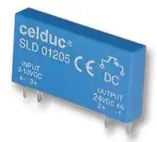
SLD03205
Solid State Relay, Slim, 4 A, PCB, Through Hole
⚠️ Reference pricing provided. In case of supply shortages, we will connect you with our trusted procurement partners to ensure your project's continuity.
- Manufacturer: CELDUC
- Product type:
- Contact Configuration:-; Load Current:4A; Operating Voltage Max:-; Relay Mounting:PCB; Relay Terminals:Through Hole; Switching Mode:-; Operating Voltage Min:-; Control Voltage Min:18VDC; Control Voltage M
- SVHC: No SVHC (27-Jun-2024)
- Load Current: 4A
- Product Range: SLD0X205 Series
- Relay Mounting: PCB
- Switching Mode: -
- Relay Terminals: Through Hole
- Control Voltage Max: 32VDC
- Control Voltage Min: 18VDC
- Contact Configuration: -
- Operating Voltage Max: -
- Operating Voltage Min: -
| Delivery and price | |
|---|---|
| Units per pack | 50 |
| Price | 17.4 € |
| Current stock | 25+ |
| Lead time | 30 days |
Datasheet

~~S/MOD/SLD0x205/F/09/07/2018~~

page 1 / 3  F/GB

## **Relais Statique miniature sortie DC** _**DC SLIM Solid State Relay**_

**DC input 24VDC 4A output**

- Compatibilité du brochage avec les Relais Electro-mécaniques .

- Commande 5 , 12, 24 et 48 VDC  selon modèles

- Sortie 24VDC  -  4A ( voir derating en température)

- Ecrêteur de surtension intégré.

- Pin to pin compatible with Electromechanic Relays.

- 5 , 12 , 24 and 48VDC control

- 24VDC   -  4A  output ( see derating curve) • Integrated clamping voltage.

**==> picture [53 x 6] intentionally omitted <==**

**----- Start of picture text -----**<br>
FILE Nr. E69913<br>**----- End of picture text -----**<br>


|**Caractéristiques de commande (à 20°C) /**<br>**Control characteristics (at 20°C)**<br>~~rs(QO~~|**Caractéristiques de commande (à 20°C) /**<br>**Control characteristics (at 20°C)**<br>~~rs(QO~~|**SLD01205 **<br>~~(QO~~|**SLD01205 **<br>~~(QO~~|**SLD01205 **<br>~~(QO~~|**SLD02205**<br>~~(QO~~|**SLD02205**<br>~~(QO~~|**SLD02205**<br>~~(QO~~|**SLD03205**|**SLD03205**|**SLD03205**||
|---|---|---|---|---|---|---|---|---|---|---|---|
|~~rs~~|~~(QO~~|**DC**<br>~~(QO~~<br>~~GO~~<br>~~GO~~|||**DC**<br>~~(QO~~<br>~~GO~~<br>~~GO~~|||**DC**<br>~~GOGG~~|||~~GG~~|
|**Parameter**<br>~~rs ~~<br>~~GD~~|**Symbol**<br> ~~(QO~~<br>~~GD~~<br>~~I~~|**Min**<br>~~(QO~~<br>~~GD~~<br>~~QD~~|**Nom **<br>~~(QO~~<br>~~GD~~<br>~~GO~~<br>~~GO~~|**Max**<br>~~(QO~~<br>~~GD~~<br>~~GO~~<br>~~GG~~|**Min**<br>~~(QO~~<br>~~GD~~<br>~~GO~~<br>~~GG~~|**Nom **<br>~~(QO~~<br>~~GD~~<br>~~GO~~<br>~~GG~~|**Max**<br>~~(QO~~<br>~~GD~~<br>~~GO~~<br>~~GG~~|**Min**<br>~~GD~~<br>~~GO~~<br>~~GO~~|**Nom**<br>~~GD~~<br>~~GG~~<br>~~GO~~|**Max **<br>~~GD~~<br>~~GG~~<br>~~GO~~|**Unit**<br>~~GD~~<br>~~GG~~|
|Tension de commande /_Control voltage_<br>~~es~~|Uc<br>~~es~~<br>~~I~~|3<br>~~es~~<br>~~QD~~|**5**<br>~~GO~~<br>~~es~~<br>~~GO~~|10<br>~~GO~~<br>~~es~~<br>~~GG~~<br>~~GO~~|7<br>~~GO~~<br>~~es~~<br>~~GG~~<br>~~GO~~|**12**<br>~~GO~~<br>~~es~~<br>~~GG~~<br>~~GO~~|20<br>~~GO ~~<br>~~es~~<br>~~GG~~<br>~~GO~~|18<br> ~~GO ~~<br>~~es~~<br>~~GO~~<br>~~GO~~|**24**<br> ~~GG~~<br>~~es~~<br>~~GO~~<br>~~GO~~|32<br>~~GG~~<br>~~es~~<br>~~GO~~<br>~~GO~~|V<br>~~GG~~<br>~~es~~|
|Courant de commande /_Control current (@ Uc nom )_<br>~~GD~~<br>~~es~~|Ic<br>~~I ~~<br>~~GD~~<br>~~QD~~|5,5<br> ~~QD ~~<br>~~GD~~<br>~~QD~~|12<br> ~~GO ~~<br>~~GD~~<br>GO|27<br> ~~GG~~<br>~~GD~~<br>~~GO~~<br>~~Ps~~|5,5<br>~~GG~~<br>~~GD~~<br>~~GO~~<br>~~GO~~|10<br>~~GG~~<br>~~GD~~<br>~~GO~~<br>~~GO~~|18<br>~~GG~~<br>~~GD~~<br>~~GO~~<br>GO|5,5<br>~~GO ~~<br>~~GD~~<br>~~GO~~<br>GO|7,7<br> ~~GO~~<br>~~GD~~<br>~~GO~~<br>~~Ge~~|10,2<br>~~GO~~<br>~~GD~~<br>~~GO~~<br>~~Ge~~|mA<br>~~GD~~|
|Tension de relachement /_Release voltage_<br>~~es~~<br>~~es~~|Uc off<br>~~es~~<br>~~QD~~|~~es~~<br>~~QD~~|~~es~~<br>GO|1,8<br>~~GO~~<br>~~es~~<br>~~Ps~~|~~GO~~<br>~~es~~<br>~~GO~~|~~GO~~<br>~~es~~<br>~~GO~~|3,6<br>~~GO~~<br>~~es~~<br>GO|~~GO ~~<br>~~es~~<br>GO|~~GO~~<br>~~es~~<br>~~Ge~~|8,3<br>~~GO~~<br>~~es~~<br>~~Ge~~|V<br>~~es~~|
|Résistance interne /_Input internal resistor_<br>~~es~~|Rc<br>~~QD~~|320<br>~~QD~~GO~~Ps~~<br>~~GO~~|||1070<br>~~GO~~<br>GO<br>~~GO~~|||3000<br>GO~~Ge~~|||Ω|


Caractéristiques générales / _General characteristics_

|Caractéristiques générales /ques générales /ues générales /générales /énérales /_General characteristics_|Caractéristiques générales /ques générales /ues générales /générales /énérales /_General characteristics_|Caractéristiques générales /ques générales /ues générales /générales /énérales /_General characteristics_|Caractéristiques générales /ques générales /ues générales /générales /énérales /_General characteristics_|Caractéristiques générales /ques générales /ues générales /générales /énérales /_General characteristics_|
|---|---|---|---|---|
|**Parameter**|**Conditions**|**Symbol**|**Typ.**||
|Plage de température de fonctionnement /_Operating temperature range_|Boitier / Case|Tc max|-20   / +80|°C|
|Plage de température de stockage /_Storage temperature range_|Boitier / Case|Tc max|-25  / +80|°C|
|Isolement entrée-sortie /_Input-output isolation_|||2500|VRMS|
|Poids /_Weight_|||8|g|
|Température de soudage max /_Max soldering heat(1 mm  boitier/case)_|10 s|Ts max|220|°C|
|Conformité /_Conformity_||IEC60947-5-1 & IEC60947-1|||
|Homologation /_Approved_||UL|||


## _**Proud to serve you**_

All technical characteristics are subject to change without previous notice. Caractéristiques sujettes à modifications sans préavis.

S/MOD/SLD0x205/F/09/07/2018

page 2 / 3  F/GB

|**Parameter**<br>~~TT—OSYOCOSCS~~|**Conditions**<br>~~TT—OSYOCOSCS~~|**Symbol**<br>~~TT—OSYOCOSCS~~|**Typ.**<br>~~TT—OSYOCOSCS~~|**Unit**<br>~~TT—OSYOCOSCS~~|
|---|---|---|---|---|
|Tension de charge /_Load voltage_<br>~~a~~|~~OQ~~|Ul<br>~~OQ~~|**24**|V|
|Plage tension de fonctionnement /_Operating range_<br>~~OQ~~|~~OQ~~|Ulmin-max<br>~~OQ~~<br>~~QC~~|0-32<br>~~OQ~~<br>~~QC~~|V<br>~~OQ~~|
|Courant nominal DC12 /_DC-12 nominal current(Resistive loads...)_<br>~~a~~|(see Fig. 2)<br>~~a~~|Il DC-12<br>~~a~~<br>~~QC~~|4<br>~~a~~<br>~~QC~~|A<br>~~a~~|
|Courant nominal DC13 /_DC13 nominal current(Electromagnets)_<br>~~OO~~|(see Fig. 2)<br>~~OO~~|Il DC-13<br>~~QC~~<br>~~OO~~|4<br>~~QC~~<br>~~OO~~|A<br>~~OO~~|
|Courant nominal DC6 /_DC-6 nominal current(Lamps)_<br>~~OGG~~|(see Fig. 2 &3)<br>~~OGG~~|Il DC-6<br>~~OGG~~|4<br>~~OGG~~|A<br>~~OGG~~|
|Courant de surcharge non répétitif /_Non repetitive overload current_<br>~~COS~~|tp=1s(Fig. 3)<br>~~COS~~|Ilpulse<br>~~COS~~|9A<br>~~COS~~|A<br>~~COS~~|
|Chute tension directe crête/_On state voltage drop_<br>~~CQ~~|@Il nom,<br>~~CQ~~|Vd<br>~~CQ~~|0,24V@2A<br>~~CQ~~|V<br>~~CQ~~|
|Résistance de sortie à l'état on /_Static output on-resistance_<br>~~OQ~~|Uc nom,Il=2A<br>~~OQ~~|R on max<br>~~OQ~~<br>~~QC~~|120<br>~~OQ~~<br>~~QC~~|mΩ<br>~~OQ~~|
|Courant de fuite état bloqué /_Off state leakage current_<br>~~a~~|@Ul=24V<br>~~a~~|Ilk max<br>~~a~~<br>~~QC~~|<1<br>~~a~~<br>~~QC~~|mA<br>~~a~~|
|Courant de charge minimum /_Minimum load current_<br>~~OO~~|~~OO~~|Ilmin<br>~~QC~~<br>~~OO~~|1<br>~~QC~~<br>~~OO~~|mA<br>~~OO~~|
|Temps de fermeture /_Turn on time_<br>~~OGG~~|Uc nom DC<br>~~OGG~~|ton  max<br>~~OGG~~|50<br>~~OGG~~|µs<br>~~OGG~~|
|Temps d'ouverture /_Turn off time_<br>~~COS~~|Uc nom DC<br>~~COS~~|toff max<br>~~COS~~|600<br>~~COS~~|µs<br>~~COS~~|
|Frequence max de commutation /_Operating switching frequency_<br>~~CQ~~|Uc nom DC<br>~~CQ~~|fs<br>~~CQ~~|100(*)<br>~~CQ~~|Hz<br>~~CQ~~|
|Transil deprotection contre les surtension/_Transient voltage suppressor_<br>~~OQ~~|~~OQ~~|~~OQ~~<br>~~QC~~|oui/yes<br>~~OQ~~<br>~~QC~~|~~OQ~~|
|-Tension d'ecrêtage /_Breakdown voltage_<br>~~a~~|@1mA<br>~~a~~|Ubr min<br>~~a~~<br>~~QC~~|36<br>~~a~~<br>~~QC~~|V<br>~~a~~|
|-Puissance maximum /_Peakpower dissipation_<br>~~OO~~|Pulse 10/1000µs<br>~~OO~~|Pr<br>~~QC~~<br>~~OO~~|600<br>~~QC~~<br>~~OO~~|W<br>~~OO~~|
|-Tension crête(écrêteur de tension)/_Peak voltage (clamping voltage)_<br>~~OGG~~|~~OGG~~|Upmax<br>~~OGG~~|60<br>~~OGG~~|V<br>~~OGG~~|
|EMC Test d'immunité conduite /_Conducted immunity level_|IEC 1000-4-4(bursts)<br>~~fC~~|1kV criterion A /4kV criterion B<br>~~fC~~|||
|EMC Test d'immunité conduite /_Conducted immunity level_|IEC 1000-4-5 (shocks)<br>~~fC~~|Control :0,5kV crit. A<br>Output 1kV crit. A<br>~~fC~~|||


(*) : Fréquence de commutation : A des fréquences élevées, les pertes en commutation peuvent entraîner un échauffement du relais plus important. Il faut donc limiter un peu le courant. A faible courant, les limites en fréquence correspondent aux temps de commutation et la fréquence de commutation peut être beaucoup plus importante.

(*) : Operating frequency : With high frequency operating, turn ON and turn OFF commutation can increase the temperature of the SSR. So, with high frequency  operating, it is necessary to limit a little bit the current. With low current, the frequency limit is given by the turn ON and turn OFF time, that means high frequency operating is possible.

Fig. 2 : Courant en fonction de la température ambiante / _Load current vs. ambient temperature characteristics_

Fig. 3 : Courant de surcharge non répétitif / _Non repetitive surge current_

## Précautions :

- Dans le cas de plusieurs modules côte à côte, prévoir un dérating en courant.

- Sur charges inductives prevoir une diode de roue libre (ou écrêteur de surtension ). Voir page 3.

_Cautions :_

- _In case of many SSRs side by side , take a derating current in to account ._

- _On inductive loads  put a free-wheeling diode (or clamp ). See page 3._

## _**Proud to serve you**_

All technical characteristics are subject to change without previous notice. Caractéristiques sujettes à modifications sans préavis.

S/MOD/SLD0x205/F/09/07/2018

page 3 / 3  F/GB

Fonctionnement sur charge Inductive _Application on Inductive load_

## Application type : _Typical application :_

a) Utilisation d'une diode de roue libre (DRL) _Using Free wheel diode (DRL)._

Electovanne / Valve

+24VDC SLD Une diode de roue libre sur la charge protège correctement le  relais mais augmente le temps d'ouverture de la charge. DRL _A free wheel diode protect the relay, but the turn OFF time increases._ 0VDC

## b) Utilisation de la protection interne au relais (Dz)

_Using internal voltage protection of the relay ( Dz)_

+24VDC La diode de protection interne au relais (Dz) peut être SLD utilisée dans la limite de sa puissance dissipée, ce qui Dz limite la fréquence de commutation : F max = 0,6/LI[2] ( L= inductance de la charge ; I = courant de charge) The internal voltage protection (Dz)of the relay can be used but the switching frequency must be adapted to the max power dissipation of the internal protection : 0VDC F max = 0,6/LI[2] ( L= inductance of the load ; I = load current)

c) Utilisation de protection transils ou VDR sur la charge :

utiliser relais de tension supérieure : voir  fiche technique SLD0x210

_Using transils or VDR protection on the load  :_

_use a higher voltage relay : see SLD0x210 data-sheet_

+24VDC SLD 0VDC **®** ~~**www.celduc.com**~~ **r     e     l     a     i     s 5, Rue Ampère BP30004     42290 SORBIERS - FRANCE** celduc__——— **Fax +33 (0) 4 77 53 85 51            Service Commercial France Tél. : +33 (0) 4 77 53 90 20 Sales Dept.For Europe Tel. : +33 (0) 4 77 53 90 21    Sales Dept. Asia : Tél. +33 (0) 4 77 53 90 19**
Updated at June 10, 2026
About Novapart
Novapart is a B2B electronic component broker specialising in stock shortages and cost reduction. We source hard-to-find parts and identify compliant alternatives across a catalogue of 410,000+ components from 500+ manufacturers.
Learn more →Stock Shortage Specialist
When a component is unavailable, discontinued or has an unacceptable lead time, we tap into our network of vetted European and Asian distributors to source what you need — without compromising on quality or traceability.
Request a quote →Compliant Alternatives
We identify pin-to-pin, electrically equivalent substitutes that meet the same certifications (RoHS, AEC-Q100, REACH) as your original specification — validated against datasheets, not just part numbers. Often at a lower cost.
BOM Analysis service →