


SL1021A260R.
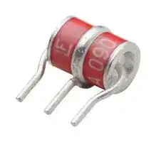
Gas Discharge Tube (GDT), SL1021A Series, 260 V, 3 Terminal Through Hole, 10 kA, 550 V
- Manufacturer: LITTELFUSE
- Product type: Gas Discharge Tubes - GDT
- Product Range: SL1021A Series
- GDT Case Style: 3 Terminal Through Hole
- DC Breakover Voltage: 260V
- Impulse Discharge Current: 10kA
- Impulse Sparkover Voltage: 550V
| Delivery and price | |
|---|---|
| Units per pack | 1 |
| Price | 0.948 € |
| Current stock | 1000+ |
| Lead time | 7 days |
**Gas Discharge Tubes** SL1021A/B Series ~~**RoHS** [|~~

## SL1021A/B Series

~~**Description**~~ GDT circuit protection devices dissipate electrical surge energy safely within a contained plasma gas. Commonly used to help protect sensitive telecom and networking equipment and lines, GDTs protect ~~ee~~ Sa from damage that may result from lightning strikes and equipment switching operations. The Littelfuse GDT series described in this document are available in a variety of leaded and surface mount forms and offered with and without optional fail-safe clip. Please refer to the electrical specifications, dimension and packaging options section of this document for additional information.

**==> picture [78 x 10] intentionally omitted <==**

**----- Start of picture text -----**<br>
Agency Approvals<br>**----- End of picture text -----**<br>


AGENCY AGENCY FILE NUMBER E128662 ~~—~~

~~**3 Electrode GDT Graphical Symbol**~~

|a||b|a = TIP<br>b = RING|
|---|---|---|---|
||||e = GROUND|
||||(center electrode)|
|e||||
|~~**Features**~~||||
|• RoHS compliant<br>• Low insertion loss|||• 10KA (A suffix devices) /<br>20KA (B suffix devices)|
|• Excellent response to<br>fast rising transients<br>• Ultra low capacitance|||surge capability tested<br>with 8/20μs pulse as<br>defined by IEC 61000-4-5<br>• Available with thermal<br>failsafe option (add ‘F’|
||||suffix to part number)|


- ~~**Applications**~~

- **SL1021:** • Telecom network • Broadband equipment interfaces • ADSL equipment •  Telephone line cards • XDSL equipment •  Repeaters • Satellite and CATV •  Modems equipment •  Line test equipment

- • Splitters • General telecom equipment

## **SL1021A/B Series:**

SL1021A/B series GDTs are designed to offer high levels of performance on fast rising transients in the range of 100V/μS to 1KV/μS, which are those most likely created by induced lightning disturbances.

These devices feature ultra low capacitance (typically 1.5pF or less) and are extremely robust with SL1021A devices able to divert a 10,000 Amp pulse without destruction, and SL1021B suffix devices able to divert a 20,000 Amp pulse without destruction.

These series offer optimized internal geometry which provide low insertion loss at high frequencies, ideal for the protection of broadband and other high speed transmission equipment.

|~~**Product Characteristics**~~|~~**Product Characteristics**~~||
|---|---|---|
||||
|**Materials**||Dull Tin Plate 17.5 ± 12.5 Microns.<br>with ceramic insulator|
|||‘LF’ mark, voltage& date code:|
|**Product Marking**||SL1021A**- Red**/White text|
|||SL1021B**- Blue**/White text|
|**Glow to arc**<br>**transition current**||~ 1Amp|
|**Glow Voltage**||~60-200 Volts|
|**Storage and Operation**<br>**Temperature**||-40 to +90°C|
|**Transverse Voltage**<br>**(Delay Time)**<br>**Arc Voltage**||< 0.2µSec(Tested to ITU-T Rec. K.12)<br>~10 to 35 Volts|
|**Holdover Voltage**||<150mS(Tested to ITU-T Rec. K.12)|


© 2015 Littelfuse, Inc. Specifications are subject to change without notice. Revised: 11/06/15

**Gas Discharge Tubes** SL1021A/B Series

## ~~**Electrical Characteristics**~~

|||**Device Specifications**(at 25°C)|**Device Specifications**(at 25°C)|**Device Specifications**(at 25°C)|**Device Specifications**(at 25°C)|**Device Specifications**(at 25°C)||||**Life Ratings**|**Life Ratings**||
|---|---|---|---|---|---|---|---|---|---|---|---|---|
|Part<br>Number|DC Voltage<br>100V/Sec.<br>MIN<br>TYP<br>MAX|||DC<br>Voltage<br>100 V/<br>μSec.|DC<br>Voltage<br>1kV/<br>μSec.|Capaci-<br>tance<br>(@1Mhz)|Insulation<br>Resistance<br>MIN|AC<br>Current<br>50Hz<br>1Sec.x101|Surge<br>Current<br>8/20μSec<br>x101|Max<br>Single<br>Surge<br>8/20μSec1|Max Single<br>Surge<br>10/350μSec1|Surge Life<br>10/1000<br>μSecx3001|
|SL1021B075<br>SL1021A090<br>SL1021B090|60<br>72|75<br>90|90<br>108||650||>1010Ω<br>(at 50V)||||4kA2<br>5kA3||
|SL1021A145<br>SL1021B145|116|145|174|500|||||||||
|SL1021A150<br>SL1021B150|120|150|180||600||||||||
|SL1021A200|150|200|250||||||||||
|SL1021A230<br>SL1021B230<br>SL1021A250<br>SL1021B250|184<br>200|230<br>250|276<br>300|450<br>500|650||||||||
|SL1021A260<br>SL1021B260<br>SL1021A300<br>SL1021B300|210<br>240|260<br>300|310<br>360|550<br>650|700<br>850|<1.5pF|>1010Ω<br>(at 100V)|10Amps|10kA2<br>20kA3|15kA2<br>25kA3|2.5kA2<br>5kA3|200Amps|
|SL1021A350<br>SL1021B350|280|350|420|700|900||||||||
|SL1021A400<br>SL1021B400<br>SL1021A420<br>SL1021B420|320<br>345|400<br>420|480<br>500|850|950||||||||
|SL1021A450<br>SL1021B450|360|450|540|900|1000||||||||
|SL1021A500<br>SL1021B500<br>SL1021A600|400<br>500<br>480<br>600<br>~~Pot~~||600<br>720|950<br>1000|1100<br>1200||||||||


NOTES:

1. Total current through centre electrode, tested in accordance with ITU-T Rec K.12

2. SL1021A series

3. SL1021B series

## **Additional Information**

**==> picture [198 x 73] intentionally omitted <==**

**----- Start of picture text -----**<br>
Datasheet Resources Samples<br>SL1021A SL1021A SL1021ASL1021A<br>kd<br>Datasheet Resources Samples<br>SL1021B SL1021B SL1021BSL1021B<br>**----- End of picture text -----**<br>


© 2015 Littelfuse, Inc. Specifications are subject to change without notice. Revised: 11/06/15

**Gas Discharge Tubes** SL1021A/B Series

**==> picture [94 x 32] intentionally omitted <==**

**==> picture [261 x 19] intentionally omitted <==**

**----- Start of picture text -----**<br>
Time vs. Current for Failsafe<br>**----- End of picture text -----**<br>


## ~~**Voltage vs. Time Characteristic**~~

**==> picture [243 x 162] intentionally omitted <==**

**----- Start of picture text -----**<br>
60<br>SL102xA with Failsafe<br>30 SL102xB or PMT8 500 Volt Higher Melting Point Solder<br>SL102xB or PMT8 350 Volt Higher Melting Point Solder<br>20 SL102xB or PMT8 90 Volt Higher Melting Point Solder<br>15<br>14<br>13<br>12<br>11<br>10<br>9<br>8<br>7<br>6<br>5<br>4<br>3<br>2<br>1<br>0.5 1 2 5 10 15 30<br>**----- End of picture text -----**<br>


**==> picture [261 x 376] intentionally omitted <==**

**----- Start of picture text -----**<br>
Max dynamic breakover<br>voltage<br>Hold-over voltage<br>On-State voltage<br>0  200  400  600  800  1000  1200<br>Time (ns)<br>t P<br>T P<br>Critical Zone<br>Ramp-up TL to TP<br>T S(max) T L t L<br>Ramp-down<br>Preheat<br>T S(min)<br>t S<br>25<br>time to peak temperature Time<br>(t 25ºC to peak)<br>Soldering Parameters - Hand Soldering<br>(V)<br>Voltage<br>Temperature<br>**----- End of picture text -----**<br>


## ~~**Soldering Parameters - Refow Soldering (Surface Mount Devices)**~~

|Refow Condition<br>Pre Heat<br>- Temperature Min (Ts(min))<br>- Temperature Max (Ts(max))<br>- Time (Min to Max) (ts)<br>Average ramp up rate (Liquidus Temp<br>(TL) to peak|Refow Condition<br>Pre Heat<br>- Temperature Min (Ts(min))<br>- Temperature Max (Ts(max))<br>- Time (Min to Max) (ts)<br>Average ramp up rate (Liquidus Temp<br>(TL) to peak|Pb – Free assembly<br>150°C<br>200°C<br>60 – 180 secs<br>3°C/second max|
|---|---|---|
|TS(max)to TL|- Ramp-up Rate|5°C/second max|
|Refow|- Temperature (TL) (Liquidus)<br>- Temperature (tL)|217°C<br>60 – 150 seconds|
|Peak Temperature (TP)||260+0/-5°C|
|Time within 5°C of actual peak<br>Temperature (tp)||10 – 30 seconds|
|Ramp-down Rate||6°C/second max|
|Time 25°C|to peak Temperature (TP)|8 minutes Max.|
|Do not exceed||260°C|


Solder Iron Temperature:  350° C +/-  5°C Heating Time:  5 seconds max.

## ~~**Soldering Parameters - Wave Soldering (Thru-Hole Devices)**~~

**==> picture [243 x 171] intentionally omitted <==**

**----- Start of picture text -----**<br>
300<br>280<br>260<br>240<br>220<br>200<br>180<br>160<br>140<br>120<br>100<br>80<br>60<br>40<br>20<br>0<br>Time (Seconds)<br>Preheat Time Cooling Time<br>Dwell Time<br>Temperature (°C) - Measured on bottom side of board 0 10 20 30 40 50 60 70 80 90 100 110 120 130 140 150 160 170 180 190 200 210 220 230 240<br>**----- End of picture text -----**<br>


## **Recommended Process Parameters:**

**==> picture [245 x 107] intentionally omitted <==**

**----- Start of picture text -----**<br>
Wave Parameter Lead-Free Recommendation<br>Preheat:<br>(Depends on Flux Activation Temperature) (Typical Industry Recommendation)<br>    Temperature Minimum: 100° C<br>    Temperature Maximum: 150° C<br>    Preheat Time: 60-180 seconds<br>Solder Pot Temperature: 280° C Maximum<br>Solder Dwell Time: 2-5 seconds<br>**----- End of picture text -----**<br>


Note: Surge Arrestors with a Failsafe mechanism should be individually examined after soldering

© 2015 Littelfuse, Inc. Specifications are subject to change without notice. Revised: 11/06/15

**Gas Discharge Tubes** SL1021A/B S ~~e~~ ries

## ~~**Device Dimensions** LO~~

NOTE: Failsafe option dimensions shown in green.

## Shaped Radial Leaded Devices:

**==> picture [202 x 273] intentionally omitted <==**

**----- Start of picture text -----**<br>
12.4 ± 1<br>[0.488 ± 0.039] Mounting Area<br>Type 04 / R  [0.464]11.8 [0.354]9.0<br>10.10 8.1.<br>[0.398] [0.319]<br>0.3mm<br>Minimum<br>Gap<br>9.9<br>[ 0.354]<br>15<br>[0.590]<br>1 6.8 1.0 DIA.<br>4.4 [0.661] [0.039]<br>[0.173]<br>4.4± 0.3 4.4± 0.3<br>[0.173± 0.12] [0.173± 0.12]<br>12.4 ± 1<br>[0.488 ± 0.039] Mounting Area<br>Type 05 / P [0.464]11.8 [0.354]9.0<br>10.10 8.1.<br>[0.398] [0.319]<br>0.3mm<br>Minimum<br>Gap<br>9.9<br>[0.354]<br>15<br>[0.590]<br>16.8 1.0 DIA.<br>4.4 [0.661] [0.039]<br>[0.173]<br>5.5± 0.3 5.5± 0.3<br>[0.216± 0.12] [0.216± 0.12]<br>**----- End of picture text -----**<br>


Core Devices:

**==> picture [202 x 267] intentionally omitted <==**

**----- Start of picture text -----**<br>
Type 01 / C  [0.464][0.398]10.1011.8 Mounting Area[0.354][0.319]9.08.1<br>0.3mm<br>Minimum<br>Gap<br>9.9<br>[0.354]<br>Straight Ra dial Leaded  Devices:<br>14.7<br>[0.579]<br>Type 06 / Y  [0.464]11.8 Mounting Area[0.354]9.0<br>[0.398]10.10 8. 1  DIA. MAX.[0.319]<br>0.3mm<br>Minimum<br>Gap<br>9.9<br>[ 0.354]<br>15<br>[0.590]<br>16.8[0.661] 1.0 DIA.[0.039]<br>6.35 ± 0.5 6.35 ± 0.5<br>[0.25 ± 0.25] [0.25 ± 0.25]<br>**----- End of picture text -----**<br>


## Straight Ra ~~dial Leaded~~ Devices:

Straight "T" Leaded Devices:

**==> picture [202 x 137] intentionally omitted <==**

**----- Start of picture text -----**<br>
Type 14 / X<br>50 ± 3<br>[1.968 ± 0.118 ]<br>[0.464]11.8 Mounting Area[0.3549.0 ]<br>10.10<br>[0.398] 8.1 DIA. MAX.<br>[0.319]<br>0.3mm<br>Minimum<br>Gap<br>23.8<br>[0.937]<br>22<br>[0.866] 1.0 DIA..<br>[0.039]<br>THi  &i<br>**----- End of picture text -----**<br>


Type “R” is available for SL1021B075 device only.

© 2015 Littelfuse, Inc. Specifications are subject to change without notice. Revised: 11/06/15

**Gas Discharge Tubes** SL1021A/B Series

## ~~**Part Numbering System and Ordering Information**~~

**==> picture [132 x 119] intentionally omitted <==**

**----- Start of picture text -----**<br>
SL102x  x  xxx  x  x   PMT8  xxx  x  x<br>Series Series<br>SL1021 PMT8<br>SL1024<br>Surge Capability ~ ] TJ<br>A = 10kA<br>B = 20kA<br>Breakdown Voltage Breakdown Voltage<br>090 = 90V 300 = 300V 090 = 90V<br>145 = 145V 350 = 350V 230 = 230V<br>150 = 150V 400 = 400V 250 = 250V<br>200 = 200V 420 = 420V 350 = 350V<br>230 = 230V 450 = 450V 400 = 400V<br>250 = 250V 500 = 500V<br>260 = 260V 600 = 600V<br>Configuration Code Configuration Code<br>(See Device Dimensions section) (See Device Dimensions section)<br>C  Y 01 10<br>R X 04 14<br>P 05 60<br>06<br>Option Code Option Code<br>Blank = No failsafe Blank = No Failsafe<br>F or G = With Failsafe F = With Failsafe<br>**----- End of picture text -----**<br>


## ~~**Packaging**~~

## **For 'SL1021A/B' device type C, R, P, Y packing**

**==> picture [9 x 8] intentionally omitted <==**

**----- Start of picture text -----**<br>
~235<br>**----- End of picture text -----**<br>


**==> picture [156 x 50] intentionally omitted <==**

**----- Start of picture text -----**<br>
Box (Cardboard)<br>Tray, Cover (PET)<br> [,<br>Tray, Bottom (PET)<br>[,— for 100 Pcs.<br>PE Form<br>~55<br>**----- End of picture text -----**<br>


## **For 'SL1021A/B' device type X packing**

**==> picture [143 x 92] intentionally omitted <==**

**----- Start of picture text -----**<br>
Ly<br>Box (Cardboard)<br>Tray (PET)<br>for 50 Pcs.<br>——<br>Sponge (PE Form)<br>~258<br>**----- End of picture text -----**<br>


**==> picture [100 x 14] intentionally omitted <==**

**----- Start of picture text -----**<br>
~135<br>-—___— ee<br>**----- End of picture text -----**<br>


**==> picture [224 x 136] intentionally omitted <==**

**----- Start of picture text -----**<br>
|||||
|---|---|---|---|
|~135|
|Device Type|Description|Quantity|
|Type|C|100pcs/tray x 5 trays per carton|500|
|Type R|100pcs/tray x 5 trays per carton|500|
|Type P|100pcs/tray x 5 trays per carton|500|
|Type Y|100pcs/tray x 5 trays per carton|500|
|Type X|50pcs/tray x 5 trays per carton|250|

**----- End of picture text -----**<br>


* Please contact the factory for further packaging information.

© 2015 Littelfuse, Inc. Specifications are subject to change without notice. Revised: 11/06/15
Updated at February 9, 2023
Founded in 1927 and headquartered in Chicago, Illinois, Littelfuse is a premier global manufacturer of circuit protection, power control, and sensing technologies. Widely recognized for pioneering the first small, fast-acting protective fuse, the company has grown into an industry leader whose highly reliable components are essential to modern industrial, transportation, and consumer electronics applications worldwide. At the core of the Littelfuse portfolio is an expansive and industry-leading range of circuit protection solutions. This encompasses a massive selection of traditional fuses, fuse holders, and resettable PTC thermistor fuses designed to safely interrupt overcurrent conditions. To defend against electrical overstress, Littelfuse also provides advanced transient voltage suppression (TVS) technologies, including thousands of specialized TVS diodes, TVS varistors, and gas discharge tubes (GDTs) that ensure robust defense against voltage spikes and environmental hazards. Beyond its foundational protection components, Littelfuse manufactures a diverse array of discrete semiconductors, sensors, and switching devices. Engineers rely on their high-performance thyristors, including TRIACs and SCRs, alongside power-efficient Schottky diodes and MOSFETs for demanding power control applications. Complemented by precision proximity sensors and highly reliable reed and solid-state relays, Littelfuse delivers the critical building blocks required for secure, efficient, and complete system design.
About Novapart
Novapart is a B2B electronic component broker specialising in stock shortages and cost reduction. We source hard-to-find parts and identify compliant alternatives across a catalogue of 410,000+ components from 500+ manufacturers.
Learn more →Stock Shortage Specialist
When a component is unavailable, discontinued or has an unacceptable lead time, we tap into our network of vetted European and Asian distributors to source what you need — without compromising on quality or traceability.
Request a quote →Compliant Alternatives
We identify pin-to-pin, electrically equivalent substitutes that meet the same certifications (RoHS, AEC-Q100, REACH) as your original specification — validated against datasheets, not just part numbers. Often at a lower cost.
BOM Analysis service →