


SJ2S-07L
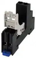
Relay Socket, DIN Rail, Screw, 8 Pins, 8 A, 250 V, RJ Series
- Manufacturer: IDEC
- Product type: Relay Sockets
- SVHC: No SVHC (15-Jan-2019)
- No. of Pins: 8Pins
- Product Range: RJ Series
- Current Rating: 8A
- Voltage Rating: 250V
- Socket Mounting: DIN Rail
- Socket Terminals: Screw
| Delivery and price | |
|---|---|
| Units per pack | 50 |
| Price | 6.47 € |
| Current stock | 50+ |
| Lead time | 30 days |
Relay Sockets

Marking Plate integrated with Release Lever

## SJ Series

## Removable Marking Plate Available

* Can be attached to the release lever and socket

Slim, space-saving relay sockets. Release lever with an integrated marking plate is provided.

**==> picture [160 x 8] intentionally omitted <==**

**----- Start of picture text -----**<br>
• See website for details on approvals and standards.<br>**----- End of picture text -----**<br>


**==> picture [205 x 50] intentionally omitted <==**

**----- Start of picture text -----**<br>
Standard Screw  Finger-safe Screw<br>Terminal Terminal<br>Removable Marking Plate<br>(accessory)<br>**----- End of picture text -----**<br>


For more information, visit htFor more information, visit h tp: /eu.idec.com **t** p:/ **/** asia.idec.com

H-041

Sockets DIN Rail Products

## Identify relays/connections ~ easily using the marking plate.

APEM

**==> picture [219 x 221] intentionally omitted <==**

**----- Start of picture text -----**<br>
1 Cut the tab using nippers. A<br>2 Lift the marking plate. B<br>Lock the marking plate<br>3 C<br>into grooves.<br>Marking area<br>4 ∗ The specified dimension is  the allowable marking area. 11.2mm 3.6mm<br>∗ See H-044 for dimensions.<br>**----- End of picture text -----**<br>


**==> picture [87 x 19] intentionally omitted <==**

**----- Start of picture text -----**<br>
Marking plate integrated<br>with release lever<br>**----- End of picture text -----**<br>


**==> picture [122 x 104] intentionally omitted <==**

**----- Start of picture text -----**<br>
C<br>A<br>B<br>**----- End of picture text -----**<br>


Switches & Pilot Lights Control Boxes Emergency Stop Switches Enabling Switches Safety Products Explosion Proof Terminal Blocks Relays & Sockets Circuit Protectors Power Supplies LED Illumination Controllers Operator Interfaces Sensors AUTO-ID

Relays

Coil voltage, signal name, circuit, etc. can be marked on the removable marking plate for easy identification of connections.

**==> picture [96 x 223] intentionally omitted <==**

**----- Start of picture text -----**<br>
5 po<br>Removable marking<br>plate (can be attached<br>at four positions on<br>the socket)<br>Marking Area<br>7.25mm<br>15.2mm<br>SJ9Z-PW<br>Removable Marking Plate<br>(accessory)<br>**----- End of picture text -----**<br>


SJ DF

SU

S

Download catalogs and CAD from ht Download catalogs and CAD from h tp: /eu.idec.com/downloads **t** p:/ **/** asia.idec.com/downloads

H-042

SJ Series Relay Sockets Slim, space-saving relay sockets. Release lever with integrated marking plate allows for easy maintenance in narrow spaces. ~~a~~ APEM Switches & Pilot Lights Shape Control Boxes Emergency Stop Switches Enabling Switches Standard Screw Terminal (1 pole) Finger-safe Screw Terminal (2 pole) Safety Products Terminal Style 1-pole 2-pole Explosion Proof Terminal No. Color Black White Black White Standard Screw Terminal SJ1S-05B SJ1S-05BW SJ2S-05B SJ2S-05BW Terminal Blocks Finger-safe Screw Terminal SJ1S-07L SJ1S-07LW SJ2S-07L SJ2S-07LW Relays & Sockets ~~=o~~ Note: Release lever is supplied with each socket. Circuit Protectors Power Supplies Specifications Applicable Relay LED Illumination Model SJ1S SJ2S 1-pole 2-pole Terminal Style Controllers Rated Current 12A 8A Socket Relay Socket Relay Operator Rated Insulation Voltage 250V AC/DC Standard Screw SJ1S-05B SJ2S-05B Interfaces Sensors Applicable Wire 2 mm[2] maximum (14 AWG) Finger-safe Terminal SJ1S-07L SJ1S-05BW RJ1S SJ2S-07L SJ2S-05BW RJ2S RJ22S Applicable Crimping 2 mm[2] × 2 Screw Terminal SJ1S-07LW SJ2S-07LW AUTO-ID Terminal Recommended Tightening 1.0 N·m Torque Applicable Crimping Terminals Screw Terminal Style M3 slotted Phillips screw Relays Terminal Strength Wire tensile strength: 50N minimum Standard Screw Terminal Finger-safe Screw Terminal ø3.2 min. Sockets Insulation Resistance 100MΩ minimum (500V DC megger) ~~=~~ 5.9 max. DIN Rail Between live and dead metal parts: Products 2000V AC, 1 minute 4.0 max. 5.3 min. Between contact and coil: 4000V AC, 1 minute Dielectric Strength Between contacts of the same pole: SJ 1000V AC, 1 minute 4.0 max. 5.3 to 6.5 Between contacts of the different poles: DF 3000V AC, 1 minute Damage limits: 90 m/s[2] 4.0 max. 5.3 to 6.5 Vibration Resistance SU Resonance: 10 to 55 Hz, amplitude 0.75 mm S Shock Resistance Damage limits: 1000 m/s[2] Note: Ring tongue terminals cannot be used on finger-safe sockets. Operating Temperature –40 to +70°C (no freezing) Storage Temperature –55 to +85°C (no freezing) Operating Humidity 5 to 85% RH (no condensation) Storage Humidity 5 to 85% RH (no condensation) Degree of Protection IP20 (finger-safe screw terminal) Weight (approx.) 30g 34g ~~—~~ H-043 For more information, visit htFor more information, visit h tp: /eu.idec.com **t** p:/ **/** asia.idec.com

SJ Series Relay Sockets

Switches & Pilot Lights Control Boxes Emergency Stop Switches Enabling Switches Safety Products Explosion Proof Terminal Blocks

## Dimensions

All dimensions in mm

## SJ1S-05B (W)

## SJ2S-05B (W)

**==> picture [470 x 518] intentionally omitted <==**

**----- Start of picture text -----**<br>
M3 Terminal Screws M3 Terminal Screws<br>*» == ~» ==<br>=<br>Cl 6 iF J vo a Cl = I 17 wo 7<br>4.3 71 ø4 4.3 71 ø4<br>11.2 11.2<br>5 (A2) 3 (14) 8 7 (22) (24) 5 6<br>(A1) ES 4 6 (A2) wr (21) — 6<br>1 — 2 (12) (11) 4 12.2 (A1) er 1 2 (12) wee (14) 4 3(11) a 12.2 H<br>(TOP VIEW) Marking Plate (TOP VIEW) Marking Plate<br>(integrated with release lever) (integrated with release lever)<br>SJ1S-07L (W) SJ2S-07L (W)<br>M3 Terminal Screws M3 Terminal Screws<br>P pera P vcr<br>4.3 71 ø3 4.3 71 ø3<br>ne ie 11.2 jp H 11.2 e<br>5 (A2) 3 (11) 4 8 (A2) 5 7 (21)6<br>(14) 6 (24) (22) 6<br>ee B Y a (14) (12) 4<br>[=e 1 (A1) (TOP VIEW) 2 (12) T Marking Plate R 12.2 [Stee]On 1 (A1) (TOP VIEW) f[,p00 4 2 (11)3 6 T Marking Plate E 12.2<br>(integrated with release lever) (integrated with release lever)<br>Replacement Parts placement Parts lacement Parts<br>Description Material Part No. Ordering Part No. Package Quantity Dimensions<br>ee QO<br>Release Lever<br>(with integrated marking plate)<br>. a a<br>s ; win<br>Plastic (gray) SJ9Z-CM SJ9Z-CMPN05 5<br>call EH<br>28.1<br>When not using marking plate<br>15.5 6 15.5 6<br>55.7 55.7<br>29.7 29.7<br>2 2<br>6 1.5 6<br>0.9 0.9 1.5<br>15.5 6 15.5 6<br>49.5 55.7 49.5 55.7<br>29.7 29.7<br>2 2<br>6 6<br>1.5<br>1.5 0.9<br>0.9<br>15.3<br>38.5<br>**----- End of picture text -----**<br>


## SJ1S-07L (W)

## Replacement Parts placement Parts lacement Parts

When ordering, specify the Ordering No.

## Accessories

|Description<br>~~es~~|Description<br>~~es~~|Material|Part No.|Ordering Part No.<br>Package Quantity|Package Quantity|Dimensions|
|---|---|---|---|---|---|---|
|Removable Marking Plate<br>~~es~~<br>~~|~~||Plastic (white)|SJ9Z-PW<br>~~ee~~|SJ9Z-PWPN10<br>~~eee~~|10|0.75<br>0.15<br>8.6<br>1.2<br>5<br>15.2<br>Marking area:<br>15.2 × 7.25 mm<br>~~-~~|
|Jumper<br>For 2 sockets<br>For 5 sockets<br>For 8 sockets<br>For 10 sockets<br>~~|~~<br>~~|~~<br>~~|~~<br>~~|~~|For 2 sockets|Nickel-coated brass<br>with polypropylene<br>coating|SJ9Z-JF2<br>~~ee~~<br>~~ee~~|SJ9Z-JF2PN10<br>SJ9Z-JF5PN10<br>SJ9Z-JF8PN10<br>SJ9Z-JF10PN10<br> ~~eee~~<br> ~~eee~~<br> ~~eee~~<br>~~eee~~|5|Terminal centers: 15.5mm<br>Rated current: 12A<br>Ensure that the total current to<br>the jumper does not exceed the<br>maximum current.|
||For 5 sockets||SJ9Z-JF5<br>~~ee ~~<br>~~ee~~<br>~~ee~~||||
||For 8 sockets||SJ9Z-JF8<br>~~ee ~~<br>~~ee~~<br>~~ee~~||||
||For 10 sockets||SJ9Z-JF10<br>~~ee ~~<br>~~ee~~||||


APEM

Relays & Sockets Circuit Protectors Power Supplies LED Illumination Controllers Operator Interfaces Sensors AUTO-ID

Relays

Sockets

DIN Rail Products SJ DF SU S

Download catalogs and CAD from ht Download catalogs and CAD from h tp: /eu.idec.com/downloads **t** p:/ **/** asia.idec.com/downloads

H-044

SJ Series Relay Sockets

APEM Switches & Pilot Lights Control Boxes

Emergency Stop Switches Enabling Switches Safety Products Explosion Proof

Terminal Blocks

Controllers Operator Interfaces Sensors AUTO-ID

Relays Sockets DIN Rail Products

## Safety Precautions

- Turn off power to the relay and the socket before starting installation, removal, wiring, maintenance, and inspection of the relays. Failure to turn power off may cause electrical shock or fire hazard.

- Use wires of the proper size to meet the voltage and current requirements.

- Make sure that relay and output equipment are wired correctly. Incorrect wiring causes overheat resulting in possible fire hazard.

- Prevent metal fragments and pieces of wire from dropping inside the socket. Ingress of such fragments and chips may cause fire hazard, damage, or malfunction.

## Instructions

## Installing relays

The relay is installed on the socket using the release lever. Leaf spring is not necessary.

## Rail Mounting and Removing

Do not mount or remove the socket in cold temperature (below –20°C), otherwise the socket may be damaged.

## Applicable Screwdriver

Relays & Sockets Circuit Protectors Power Supplies LED Illumination

Standard Screw Terminal

**==> picture [204 x 115] intentionally omitted <==**

**----- Start of picture text -----**<br>
Standard Screw Terminal<br>Phillips: ø6.4 mm maximum<br>Slotted: Shown at right Diameter:<br>ø6.4mm max<br>0.8mm max. 6.4mm max.<br>Finger-safe Screw Terminal<br>Phillips: ø5.5 mm maximum<br>Slotted: Shown at right Diameter:<br>5.5mm max<br>0.8mm max. 5.5mm max.<br>**----- End of picture text -----**<br>


## Installing relays

1. Unlock the release lever by pulling down as shown with arrow ➀.

2.  Press the relay against the socket as shown with arrow ➁. Make sure that the relay is firmly in place.

3.  Confirm that the relay is securely installed in the socket. When installed properly, the relay and the socket look as shown in ➂

**==> picture [281 x 201] intentionally omitted <==**

**----- Start of picture text -----**<br>
➀ ➁<br>SJ<br>DF<br>SU<br>S<br>➂<br>Correct Incorrect<br>Latch is inserted into the The latch is not inserted into<br>groove on top of the relay. the groove on top of the relay.<br>**----- End of picture text -----**<br>


## Caution

**==> picture [122 x 115] intentionally omitted <==**

## Removing the relay

- ➀  Lightly press the relay to prevent it from falling off.

- ➁  Pull down the release lever to the direction shown by the arrow until it touches the socket. Pull down further, and the lever will be detached from the socket.

## Caution

Make sure that wire or finger is not caught between the release lever and socket.

Because release lever is removable, make sure not to apply excessive force. Otherwise the relay may fall and result in damage.

## Panel Mounting

Insert the anti-rotation projection into the anti-rotation hole. Mount the socket onto the panel using M3 screws (not provided). Use a screwdriver with diameter of ø5.5mm maximum.

## Mounting Hole Layout

**==> picture [228 x 94] intentionally omitted <==**

**----- Start of picture text -----**<br>
SJ1S-05B (W), SJ2S-05B (W) Screw Hole (ø5.6mm)<br>ø3.5 hole 30.0 [±0.1] ø4.2 hole<br>(or M3 hole) (anti-rotation hole)<br>SJ1S-07L (W), SJ2S-07L (W)<br>ø3.5 hole 39.5 [±0.1] ø3.2 hole<br>(or M3 hole) (anti-rotation hole)<br>Anti-rotation Projection<br>**----- End of picture text -----**<br>


Tighten the mounting screws to a torque of 1.0 N·m maximum. Tightening with higher torque will damage the socket.

The round rib projecting from the socket bottom prevents rotation when the socket is mounted on the panel directly. Ensure to insert the rib into the anti-rotation hole, otherwise the socket may be damaged.

## Removing the Release Lever

**==> picture [69 x 56] intentionally omitted <==**

Pull down the release lever to the direction shown by the arrow until it touches the socket. Pull down further, and the release lever will be detached from the socket.

## Caution

Make sure that the relay has been removed from the socket before removing the release lever. If the release lever is removed when the relay is installed on the socket, the relay may fall out.

Ensure that the relay is installed in the socket completely.

For more information, visit htFor more information, visit h tp: /eu.idec.com **t** p:/ **/** asia.idec.com

H-045

SJ Series Relay Sockets

Switches & Pilot Lights Control Boxes Emergency Stop Switches Enabling Switches Safety Products Explosion Proof Terminal Blocks Relays & Sockets Circuit Protectors Power Supplies

AUTO-ID

## Instructions

## Installing the Release Lever

- ➀ Attach part A to part B.

- ➁  Slide the release lever in the direction of the arrow until part A runs out of part B.

- ➂  Rotate the release lever, with the center of rotation at part C until part A touches the rotation axis.

- ➃ Push the rib of the release lever against the socket.

- ➄ Release lever is installed.

**==> picture [236 x 139] intentionally omitted <==**

**----- Start of picture text -----**<br>
➀ ➁ ➂<br>Rotation Axis<br>Part B Part C<br>Part A<br>➃ ➄<br>Part D Rib<br>**----- End of picture text -----**<br>


## Using Marking Plate integrated with SJ9M-CM Release Lever

- ➀ Using the nippers, cut the joint (Note).

- ➁ Lift the marking plate as shown with the arrow.

- ➂ Latch the marking plate into the grooves.

**==> picture [228 x 170] intentionally omitted <==**

**----- Start of picture text -----**<br>
➀ ➁<br>Grooves<br>Cut here SJ9Z-CM Lift<br>Nipper (release lever)<br>➂<br>Note : Applicable nipper tip: 0.7mm maximum.<br>Make sure to cut the joint before installing the relay.<br>6.0mm<br>1.0mm<br>12.2mm<br>Marking Plate Nipper Tip Joint<br>(TOP VIEW)<br>6.7mm 0.7mm max.<br>0.8mm 1.5mm<br>**----- End of picture text -----**<br>


The integrated marking plate must be Screwdriver retracted to the original position when wiring. RJ relay The SJ9Z-CM integrated marking plate can be lifted and retracted for 50 times maximum. SJ socket

**==> picture [34 x 32] intentionally omitted <==**

## Using SJ9Z-PW Removable Marking Plate (optional)

- ➀ Insert the marking plate into the slot on the release lever or socket.

Note:  SJ9Z-PW removable marking plate cannot be installed on the SJ1S-05B (W)/SJ2B-05B (W) socket.

- ➁ The marking plate is installed.

**==> picture [219 x 124] intentionally omitted <==**

**----- Start of picture text -----**<br>
➀ SJ9Z-PW SJ9Z-PW<br>Detachable Marking  Detachable Marking<br>Plate (optional) Plate (optional)<br>SJ9Z-CM SJ1/2S-07L (W)<br>Release Lever Relay Socket<br>➁<br>15.2mm<br>Marking Plate<br>(TOP VIEW)<br>8.6mm<br>**----- End of picture text -----**<br>


## Current

Check the current of relay and ensure that the current is maintained below the values shown in the following table.

**==> picture [239 x 94] intentionally omitted <==**

**----- Start of picture text -----**<br>
Model SJ1S-05B SJ1S-07L SJ2S-05B SJ2S-07L<br>Operating temperature  70ºC 55ºC 40ºC 70ºC 55ºC 40ºC 70ºC 55ºC 40ºC 70ºC 55ºC 40ºC<br>highest limit<br>Single mount 12A 12A 8A 8A<br>When DC<br>11A 10A 7A 6A 7A<br>relay is  12A 12A 8A<br>(*1) (*2) (*4) (*5) (*3)<br>Collective  mounted<br>8A<br>mount When AC  — — 11A — 7A<br>relay is  (*1) 12A (*2) (*1) [12A] (*4) [—] 8A (*5) (*3)<br>mounted<br>**----- End of picture text -----**<br>


- *1) 12A when there is 5mm or more space between adjecent socket.

- *2) 12A when there is 10mm or more space between adjecent socket.

- *3) 8A when there is 5mm or more space between adjecent socket.

- *4) 8A when there is 10mm or more space between adjecent socket.

- *5) 8A when there is 15mm or more space between adjecent socket.

## APEM

LED Illumination Controllers

Operator Interfaces Sensors

Relays

Sockets

DIN Rail Products

SJ DF

SU

S

Download catalogs and CAD from ht Download catalogs and CAD from h tp: /eu.idec.com/downloads **t** p:/ **/** asia.idec.com/downloads

H-046
Updated at June 6, 2026
Founded in 1945, IDEC is a globally recognized leader in industrial automation, machine safety, and control products. Renowned for pioneering innovations in Human-Machine Interface (HMI) systems, the company is dedicated to creating a safe and efficient harmony between advanced workplace technology and human operators. At the core of IDEC’s extensive portfolio is a comprehensive selection of high-performance relays designed for demanding industrial environments. This includes a broad range of electromechanical power relays, solid-state relays, contactors, and critical safety relays, supported by a wide array of specialized relay accessories to ensure reliable and efficient switching. Beyond switching components, IDEC provides complete solutions for modern control panels and automated systems. Their robust engineering extends to advanced panel displays and instrumentation, precision light sensors, and dependable AC/DC power converters. With additional offerings in industrial switches, visual signaling units, and DIN rail terminal blocks, IDEC equips engineers with the high-quality components required to build secure, next-generation automation infrastructure.
About Novapart
Novapart is a B2B electronic component broker specialising in stock shortages and cost reduction. We source hard-to-find parts and identify compliant alternatives across a catalogue of 410,000+ components from 500+ manufacturers.
Learn more →Stock Shortage Specialist
When a component is unavailable, discontinued or has an unacceptable lead time, we tap into our network of vetted European and Asian distributors to source what you need — without compromising on quality or traceability.
Request a quote →Compliant Alternatives
We identify pin-to-pin, electrically equivalent substitutes that meet the same certifications (RoHS, AEC-Q100, REACH) as your original specification — validated against datasheets, not just part numbers. Often at a lower cost.
BOM Analysis service →