
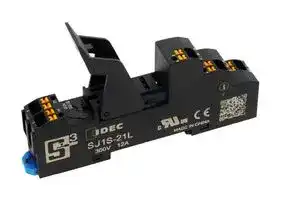


SJ1S-21L
RELAY SOCKET, 1 POLE, DIN RAIL, 5PIN
- Manufacturer: IDEC
- Product type: Relay Sockets
- Socket Mounting:DIN Rail; Socket Terminals:Push In; No. of Pins:5Pins; Current Rating:-; Voltage Rating:-; Product Range:SJ Series 35AJ1848
- No. of Pins: 5Pins
- Product Range: SJ Series
- Current Rating: -
- Voltage Rating: -
- Socket Mounting: DIN Rail
- Socket Terminals: Push In
| Delivery and price | |
|---|---|
| Units per pack | 250 |
| Price | 4.75 € |
| Current stock | 25+ |
| Lead time | 30 days |
Relay Sockets SJ series

One step wiring Easy & quick connection

IDEC CORPORATION

## - Push in

## Time saving & efficient

## ■ Save up to 55% in wiring time

Wiring time reduced greatly compared with

pray 5 } fada a conventional screw terminals. (Compared with IDEC products) 'iI Approx. 55% reduced f!! ekfini Push-in E- #2 SJ Series l ! l = > Conventional Screw terminal

**==> picture [57 x 6] intentionally omitted <==**

**----- Start of picture text -----**<br>
*) Based on IDEC research<br>**----- End of picture text -----**<br>


## ■ Reduce maintenance work

Push-in terminals eliminate the need for torque maintenance such as tightening of screws because screws are not used.

**==> picture [130 x 244] intentionally omitted <==**

**----- Start of picture text -----**<br>
Retightening<br>required<br>ipC4<br>Screw terminal<br>No<br>retightening<br>Push-in<br>**----- End of picture text -----**<br>


## Highly reliable

## ■ High visibility

The terminal number on the socket can be clearly seen on the socket preventing incorrect wiring. Also, the distinct color pusher prevents a flat blade screwdriver from being inserted into the wire port.

## Wide range of options

## ■ Terminal jumpers

Easy wiring to coil side.

**==> picture [444 x 188] intentionally omitted <==**

**----- Start of picture text -----**<br>
Wire port<br>Terminal no. (white)<br>Note) The rated current is 2A.<br>Pusher (orange)<br>■ Marking plate<br>Test point<br>A marking plate enables easy identification of<br>connections. Maintenance time is reduced.<br>Release lever<br>;<br>i f Marking plate 26S<br>insert hole<br> (i<br>Contact terminal<br>Coil terminal<br>**----- End of picture text -----**<br>


## - ■ Vibration resistant

Safe and reliable Push-in connection achieves high contact reliablity and vibration resistance regardless of the wire size or shape.

## Safe & easy

■ Equipped with a release lever The release lever easily holds and removes the relay.

**==> picture [148 x 6] intentionally omitted <==**

**----- Start of picture text -----**<br>
Before inserting wire Wire inserted<br>**----- End of picture text -----**<br>


## - ■ IP20 Finger safe

- IEC60529 finger safe design. IP20 protection. Safe contact protection structure prevents electric shock.

## ■ IDEC RF2 force guided relays can be mounted

**==> picture [71 x 14] intentionally omitted <==**

**----- Start of picture text -----**<br>
RF2 force  RJ series<br>guided relays  relays<br>**----- End of picture text -----**<br>


**==> picture [179 x 7] intentionally omitted <==**

**----- Start of picture text -----**<br>
Note) When using with RF2S force guided relay, use at 150V maximum.<br>**----- End of picture text -----**<br>


3

## **SJ Series Relay Sockets**

Push-in relay sockets reduce wiring by 55%*

* Compared with conventional screw terminal relay sockets.

**==> picture [510 x 539] intentionally omitted <==**

**----- Start of picture text -----**<br>
Relay Sockets  Package Quantity: 1  Applicable Relay<br>Shape No. of Poles Part No. (Ordering No.) No. of Poles Socket Relay<br>1 SJ1S-21L RJ1S<br>2 SJ2S-21L RJ2S, RJ22S, RF2S<br>1 SJ1S-21L<br>• For details on RJ series relay, see catalog.<br>• When using the SJ socket with RJ series relay,<br>be sure to note the derating characteristics.<br>= oo<br>Derating Curve<br>2 SJ2S-21L<br>12<br>1110 PPtSERREEt tTPA N RANGAANUE<br>9<br>8 PPP tT EENNN<br>Specifications and Ratings 7 Pt ee tT EE I<br>Part No. SJ2S-21L SJ4S-21L 6 PtSRRTee teeENeeeeTTe<br>5<br>No. of Poles 1 2<br>4<br>Rated Insulation  SJ1S-21L (DC coil)<br>Voltage 300V AC/DC (*1) 3 ml SJ1S-21L (AC coil) yl ty<br>Rated Thermal   12A 8A 2 mlmi SJ1S-21L single mount yli?ty<br>Current (*2) 1<br>| ET TTTTrTrre<br>0 i tl it<br>Solid wire / stranded wire: 0 10 20 30 40 50 60 70<br>     0.14 to 1.5mm2, AWG26 to 16<br>Stranded wire with ferrule (without insulated cover):<br>Applicable Wire<br>     0.5 to 1.5mm [2] , AWG20 to 16<br>Stranded wire with ferrule (with insulated cover):  8<br>     0.14 to 1.0mm [2] , AWG26 to 18<br>7 PTT TTT SONLETTEN |<br>Insulation Resistance 100MΩ min. (500V DC megger) 6<br>CCPC<br>2500V AC, 1 min.  5 it ETT PY TAN<br>Dielectric Strength (between live and dead metal parts, between live<br>SERRERRERRYEEEE<br>metal parts of the different poles) 4<br>Vibration Resistance (Damage Limits) 10 to 55 Hz, amplitude 1.5 mm 3 pj tii SJ2S-21L  tri (DC coil  tity ) | fq<br>Shock Resistance  2 SJ2S-21L (AC coil)<br>50G (when using release lever)<br>(Damage Limits) | SJ2S-21L single mount ieee<br>1<br>Operating<br>–40 to +70°C (no freezing)<br>Temperature 0 PTT ETE ETT Tt LE<br>Operating Humidity 5 to 85% RH (no condensation) 0 10 20 30 40 50 60 70<br>Storage Temperature –40 to +70°C (no freezing)<br>Storage Humidity 5 to 85% RH (no condensation)<br>Degree of Protection IP20 (IEC 60529)<br>Weight (approx.) 35g 43g<br>Applicable Standards UL508, CSA C22.2 No.14, IEC61984<br>Rated Current (A)<br>Rated Current (A)<br>**----- End of picture text -----**<br>


- *1) When using the socket with RF2S Force Guided Relay, the rated insulation voltage is 150V AC/DC.

- *2) Be sure to note the derating characteristics.

4

SJ Series Relay Sockets

## **Dimensions**

## SJ2S-21L

**==> picture [342 x 276] intentionally omitted <==**

**----- Start of picture text -----**<br>
SJ1S-21L<br>63 63<br>16 i, 43 16 43<br>Terminal Arrangement Terminal Arrangement<br>(4)11 (6)21 (3)11<br>(3)14 (5)24 (4)14<br>(2)12 (7)22 (2)12<br>(5)A2 (1)A1 (8)A2 (1)A1<br>Jumper Port Jumper Port<br>TOP VIEW TOP VIEW<br>102 102<br>**----- End of picture text -----**<br>


All dimensions in mm.

Note) The numbers in parentheses (   ) are values accoring to NEMA standards.

**Maintenance Parts** Function Shape Material Part No. Ordering No. Remarks ~~es esOO~~ Release Plastic SJ9Z-C21R SJ9Z-C21R Lever 24 **Accessories** When ordering, specify the Ordering No. Function Shape Material Part No. Ordering No. Remarks ~~I~~ Marking Plate Plastic (white) SJ9Z-P2100W SJ9Z-P2100W Bronze (tin-plated) A2 terminal of the coil is connected. Jumper Insulation: PBT SU9Z-J2102A SU9Z-J2102A The rated current is 2A. plastic ~~ee ee es~~ • Length: 1m DIN Rail Aluminum BAA1000 BAA1000 • Width: 35mm • Weight: 200g (approx.) ~~|_| fH | |~~ ~~**|**~~ Metal Weight: 15g (approx.) End Clip BNL6 BNL-6 Use end clips when mounting multiple sockets on (zinc-plated steel) the DIN rail. ~~Cm~~ Thickness: 5 mm DIN Rail Spacer Plastic (black) SA-406B SA-406B Used for adjusting spacing between sockets mounted on a DIN rail.

**Accessories** When ordering, specify the Ordering No.

5

SJ Series Relay Sockets

## Instructions ~~LC~~

## **Identifying the Socket**

## **Parts Description**

SJ1S and SJ2S can be identified by the part number marked on the side.

|No. of Poles||Part No.||
|---|---|---|---|
|1||SJ1S-21L||
|2||SJ2S-21L||
|**Applicable Wire**|**Applicable Wire**||Part No.<br>Marking|


## **Applicable Wire**

When wiring, use the applicable wires shown below. Applicable Wire and Specifications Applicable Wire 0.14 to 1.50mm[2] (AWG16 to 26) (Stranded Wire, Solid Wire) Wire Strip Length (*1) 10 to 11mm Ferrule Size (*2) H0.5 to H1.5 (Without insulated cover) ~~n~~ (Weidmüller) H0.14  to H1.0 ~~e~~ (With insulated cover) *1)  Strip the sheath of the wire 10 to 11 mm from the end. 10 to 11mm *2) When using a ferrule, refer to "Wire Size and Recommended Ferrule" below. ~~4p~~

Note: Make sure that the stranded wires do not loosen when using wiring without ferrules.

## **Wire Size and Recommended Ferrules**

## Ferrules without Insulated Covers

|Applicable Wire<br>(Stranded Wire)|Applicable Wire<br>(Stranded Wire)|Wire Strip Length|Part No.|
|---|---|---|---|
|AWG|mm2|||
|20|0.50|10 to 11 mm|H0.5/10|
|18|0.75|10 to 11 mm|H0.75/10|
|18|1.00|10 to 11 mm|H1.0/10|
|16|1.50|10 to 11 mm|H1.5/10|


**==> picture [104 x 172] intentionally omitted <==**

**----- Start of picture text -----**<br>
COM Wire port<br>terminal Pusher<br>Test point<br>NO Wire port<br>terminal Pusher<br>Test point<br>NC Wire port<br>terminal Pusher<br>Test point<br>—<br>Test point<br>COIL Pusher<br>terminal Wire ports<br>_BS= Jumper port<br>Clamp<br>**----- End of picture text -----**<br>


Note: Two wire ports for each terminal

## **Inserting the Wire**

Wire with ferrule or solid wire

- 1) Insert the wire to the back of the wire port.

- 2) Wiring is complete. Pull the wire lightly to make sure that the wire does not pull out from the socket.

## Ferrules with Insulated Covers

|Applicable Wire<br>(Stranded Wire)|Applicable Wire<br>(Stranded Wire)|Wire Strip Length|Part No.|
|---|---|---|---|
|AWG|mm2|||
|26|0.14|10 to 11 mm|H0.14/12 GR SV|
|24|0.25|10 to 11 mm|H0.25/12 HBL|
|22|0.34|10 to 11 mm|H0.34/12 TK|
|20|0.50|10 to 11 mm|H0.5/14 OR|
|||12 to 13 mm|H0.5/16 OR|
|18|0.75|10 to 11 mm|H0.75/14 W|
|||12 to 13 mm|H0.75/16 W|
|18|1.00|10 to 11 mm|H1.0/14 GE|
|||12 to 13 mm|H1.0/16 GE|


## Stranded wire

- 1) Push the pusher (orange button) using a flat blade screwdriver.

- 2) Insert the wire fully in the wiring port while pressing the pusher

- 3) Release the flat blade screwdriver. Wiring is complete. Pull the wire lightly to make sure that the wire does not pull out from the socket.

Recommended Tools (Optional)

|Name|Part No.|
|---|---|
|Crimping tool|PZ6 ROTO L|
|Flat blade screwdriver|SDS 0.4×2.5×75|


Note 1) Note the crimping dimensions when using tools other than the recommended crimping tool. For details, see page 7.

Note 2) Use a flat blade screwdriver with a blade size of 0.4×2.5mm.

|Applicable Wire<br>(Stranded Wire)<br>~~._~~|Applicable Wire<br>(Stranded Wire)<br>~~._~~|PHOENIX CONTACT<br>~~Bagg~~|PHOENIX CONTACT<br>~~Bagg~~|WAGO<br>~~Bagg~~|WAGO<br>~~Bagg~~|
|---|---|---|---|---|---|
|||Without<br>Insulation Cover<br> ~~Bagg~~|With<br>Insulation Cover<br>~~Bagg~~|Without<br>Insulation Cover<br>~~Bagg~~|With<br>Insulation Cover<br>~~Bagg~~|
|AWG<br>~~._~~<br>~~Se~~|mm2<br>~~._ ~~<br>~~Se~~|||||
|26<br>~~a~~|0.14<br>~~a~~|—|AI 0.14-8 GY-1000|—|—|
|24<br>~~a~~<br>~~a~~<br>~~|~~|0.25<br>~~a~~<br>~~a~~<br>|—<br>~~a~~<br>|AI 0.25-8 YE|—|FE-0.25-8N-YE|
|22<br>~~a~~<br>~~a~~<br>~~|~~|0.34<br>~~a ~~<br>~~a~~<br>~~|~~|—<br> ~~a~~<br>~~-_~~|AI 0.34-8 TQ|—|FE-0.34-8N-TQ|
|20<br>~~a ~~<br>~~|~~<br>~~a~~|0.50<br> ~~a~~<br>~~|~~<br>~~a~~|A 0.5-8<br>~~-_~~|AI 0.5-8 WH|FE-0.5-8|FE-0.5-8N-WH|
|||A 0.5-10<br>~~-_~~|AI 0.5-10 EH<br>~~ee~~|FE-0.5-10<br>~~ee~~|FE-0.5-10N-WH<br>~~es~~|
|18<br>~~| ~~<br>~~a~~<br>~~| |;~~|0.75<br> ~~| ~~<br>~~a~~<br>~~|;~~|A 0.75-8<br> ~~-_~~|AI 0.75-8 GY<br>~~ee~~|FE-0.75-8<br>~~ee~~|FE-0.75-8N-GY<br>~~es~~|
|||A 0.75-10<br>~~|;~~|AI 0.75-10 GY<br>~~ee~~|FE-0.75-10<br>~~ee~~|FE-0.75-10N-GY<br>~~es~~|
|18<br>~~a~~<br>~~| |;~~|1.00<br>~~a~~<br>~~|;~~|A 1.0-8<br>~~|;~~|—<br>~~ee~~|FE-1.0-8<br>~~ee ~~|—<br> ~~es~~|
|||A 1.0-10<br>~~|;~~|—<br>~~a~~|FE-1.0-10|—|
|16<br>~~| |;~~<br>~~a~~|1.50<br>~~|;~~<br>~~a~~|A 1.5-10<br>~~|;~~<br>~~a~~|—<br>~~a~~<br>~~a~~|FE-1.5-10<br>~~a~~|—<br>~~a~~|


## **Removing the Wire**

- 1) Push the pusher using a flat blade screwdriver.

- 2) Pull out the wire while pressing the pusher.

- 3) Release the flat blade screwdriver.

Note) Check each company's catalog for details.

6 ~~re~~

SJ Series Relay Sockets

## Instructions

## **Note**

- After wiring, tug lightly to make sure that the wire is properly connected.

- Operate the pusher with a force of 40N. Do not press excessively.

- Do not pull the wire out without depressing the pusher. When pulling the wire, be sure to pull in a straight direction. Otherwise, the socket may be damaged.

- Use a recommended flat blade screwdriver with the blade size of 0.4×2.5mm.

- When mounting multiple sockets on a DIN rail, be sure to secure both side with end clips (BNL6).

## **Crimping of Ferrules and Wiring**

- Choose an appropriate ferrule for the wire.

- Cut the wire carefully to get a flat end.

- Make sure that ferrule sleeve is completely filled by the conductor. Depending on the cross section, the conductor should protrude approx. 0 to 1 mm from the ferrule sleeve. —e T_ 0 to 1mm

## Removing the Relay

Lightly press the relay to prevent it from falling off. Then pull down the release lever to the direction shown by the arrow and the remove the socket.

**==> picture [158 x 101] intentionally omitted <==**

**----- Start of picture text -----**<br>
Relay installed Relay removed<br>|<br>kee he<br>Z R<br>Lever touches the socket<br>**----- End of picture text -----**<br>


Note)

- Make sure that wire or finger is not caught between the release lever and socket.

- Because release lever is removable, make sure not to apply excessive force. Otherwise the relay may fall and result in damage.

## **Installing the Marking Plate**

- When crimping, refer to the instructions of the crimping tool.

## Crimping dimensions: W2.4×H1.9 mm

Install the marking plate as shown in the diagram below. Mark on the surface using an oil-based marker,or affix a sticker with markings.

The size of the marking surface is 8.4mm × 15mm.

Maximum connectable crimping size is W2.4×H1.9. Make sure that the ferrule size will be smaller than this dimension.

**==> picture [18 x 6] intentionally omitted <==**

**----- Start of picture text -----**<br>
1.9mm<br>**----- End of picture text -----**<br>


**==> picture [40 x 6] intentionally omitted <==**

**----- Start of picture text -----**<br>
SJ9Z-P2100W<br>**----- End of picture text -----**<br>


2.4mm

- Note 1) If a tool other than the recommended crimping is used, the ferrule may not be crimped to the appropriate size and the clamp or spring inside the socket may be deformed and may not operate normally.

Note 2) Pin crimp terminals cannot be used.

## **Installing / Removing the Relay**

## Installing the Relay

1. Unlock the release lever by pulling 2.  Press the relay against the socket down as shown with arrow ➀. as shown with arrow ➁. Make sure that the relay is firmly in place.

**==> picture [179 x 207] intentionally omitted <==**

**----- Start of picture text -----**<br>
① ②<br>gor Ry<br>relay may fall off if it is not installed properly.<br>Relay installed Lever hook<br>Relay<br>case<br>= 4<br>Hook is in the groove<br>of the relay<br>**----- End of picture text -----**<br>


Note: Confirm that the relay is securely installed in the socket. The relay may fall off if it is not installed properly.

## **Using the Jumper**

Insert the jumper to the back of the jumper slot. To remove, insert the small flat blade driver into the slot below and pull out. Because the rated current is 2A, use at 2A maximum.

**==> picture [58 x 34] intentionally omitted <==**

**----- Start of picture text -----**<br>
Insertion slot<br>SU9Z-J2102A<br>**----- End of picture text -----**<br>


## **Installing the Release Lever**

To install the release lever, attach to the protrusion on the socket as shown below.

**==> picture [162 x 25] intentionally omitted <==**

**----- Start of picture text -----**<br>
SJ9Z-C21R protrusion<br>for installation<br>SJ9Z-C21R<br>**----- End of picture text -----**<br>


7

SJ Series Relay Sockets

## Applicable Relay

## - Applicable Relay (RJ Series  Terminal Style: Plug in)

**==> picture [542 x 24] intentionally omitted <==**

**----- Start of picture text -----**<br>
1-pole (SPDT) 2-pole (DPDT) 2-pole (bifurcated contacts DPDT)<br>Style<br>Part No. Code Part No. Code Part No. Code<br>**----- End of picture text -----**<br>


|Style|1-pole (SPDT)|1-pole (SPDT)|2-pole (DPDT)|2-pole (DPDT)|2-pole (bifurcated contacts DPDT)|2-pole (bifurcated contacts DPDT)|
|---|---|---|---|---|---|---|
||Part No.|Code|Part No.|Code|Part No.|Code|
||||||||
|Standard<br>(with LED Indicator)|RJ1S-CL- *|A12, A24, A100, A110|RJ2S-CL- *|A12, A24, A100, A110|RJ22S-CL- *|A12, A24, A100, A110, A115, A120|
|||A200, A220||A200, A220||A200, A220, A230, A240|
|||D5, D6, D12, D24, D48||D5, D6, D12, D24, D48||D5, D6, D12, D24, D48|
|||D100||D100||D100|
|Standard<br>(*1)|RJ1S-C- *|A12, A24, A100, A110|RJ2S-C- *|A12, A24, A100, A110|RJ22S-C- *|A12, A24, A100, A110, A115, A120|
|||A200, A220||A200, A220||A200, A220, A230, A240|
|||D5, D6, D12, D24, D48||D5, D6, D12, D24, D48||D5, D6, D12, D24, D48|
|||D100||D100||D100|
|With forward polarity diode<br>(with LED indicator)|RJ1S-CLD- *|D5, D6, D12, D24, D48|RJ2S-CLD- *|D5, D6, D12, D24, D48|RJ22S-CLD- *|D5, D6, D12, D24, D48|
|||D100||D100||D100|
|With forward polarity diode<br>(without LED indicator)|RJ1S-CD- *|D5, D6, D12, D24, D48|RJ2S-CD- *|D5, D6, D12, D24, D48|RJ22S-CD- *|D5, D6, D12, D24, D48|
|||D100||D100||D100|
|With reverse polarity diode<br>(with LED indicator)|RJ1S-CLD1- *|D5, D6, D12, D24, D48|RJ2S-CLD1- *|D5, D6, D12, D24, D48|RJ22S-CLD1- *|D5, D6, D12, D24, D48|
|||D100||D100||D100|
|With reverse polarity diode<br>(without LED indicator)|RJ1S-CD1- *|D5, D6, D12, D24, D48|RJ2S-CD1- *|D5, D6, D12, D24, D48|RJ22S-CD1- *|D5, D6, D12, D24, D48|
|||D100||D100||D100|
|With RC<br>(with LED indicator)|RJ1S-CLR- *|A12, A24, A100, A110|RJ2S-CLR- *|A12, A24, A100, A110|RJ22S-CLR- *|A12, A24, A100, A110, A115, A120|
|||A200, A220||A200, A220||A200, A220, A230, A240|
|With RC<br>(without LED indicator)|RJ1S-CR- *|A12,A24,A100,A110|RJ2S-CR- *|A12,A24,A100,A110|RJ22S-CR- *|A12,A24,A100,A110,A115,A120|
|||A200, A220||A200, A220||A200, A220, A230, A240|


Coil voltage other than the above are available (A115, A120, A230, A240)

## Applicable Relay (RF2 Series)

**==> picture [542 x 22] intentionally omitted <==**

**----- Start of picture text -----**<br>
Terminal Style Contact Configuration Rated  LED Indicator w/diode of reverse  Degree of Protection Part No.<br>Coil Voltage polarity coil Flux-tight (RTII) Sealed (RTIII)<br>**----- End of picture text -----**<br>


|Terminal Style|Contact Confguration|Rated<br>Coil Voltage|LED Indicator|w/diode of reverse<br>polarity coil|Degree of Protection|Degree of Protection|Part No.|
|---|---|---|---|---|---|---|---|
||||||Flux-tight (RTII)|Sealed (RTIII)||
|||||||||
|Plug-in|SPST-NO +<br>SPST-NC|12V DC|√|√|√|—|RF2S-1A1BLD1-D12|
|||24V DC|—|—|√|—|RF2S-1A1B-D24|
||||—|√|√|—|RF2S-1A1BD1-D24|
||||√|√|√|—|RF2S-1A1BLD1-D24|
||||√|√|—|√|RF2S-1A1BLD1K-D24|
|||48V DC|—|—|√|—|RF2S-1A1B-D48|
||||√|√|√|—|RF2S-1A1BLD1-D48|
||||√|√|—|√|RF2S-1A1BLD1K-D48|
||DPDT (*2)|24V DC|—|—|√|—|RF2S-2C-D24|
||||—|√|√|—|RF2S-2CD1-D24|
||||√|√|√|—|RF2S-2CLD1-D24|
||||√|√|—|√|RF2S-2CLD1K-D24|


*1) When using with RF2S force guided relay, use at AC/DC 150V maximum.

*2) When using DPDT model as a force guided relay, use in SPST-NO+SPST-NC wiring (EN50205).

## 800.262.4332 www.IDEC.com/usa

## _**Think Automation and beyond...**_

**Technical support:** support@idec.com

**Sales support:** sales@idec.com

## **www.IDEC.com**

## **USA**

**IDEC Corporation** Tel: (408) 747-0550 opencontact@IDEC.com

## **Canada**

**IDEC Canada Ltd.** Tel: (905) 890-8561 sales@ca.IDEC.com

## **Australia**

**IDEC Australia Pty. Ltd.** Tel: +61-3-8523-5900 sales@au.IDEC.com

## **Japan**

**IDEC Corporation** Tel: +81-6-6398-2527 marketing@IDEC.co.jp

## **United Kingdom**

**IDEC Electronics Ltd.** Tel: +44-1256-321000 sales@uk.IDEC.com

## **Germany**

## **IDEC Elektrotechnik GmbH**

Tel: +49-40-253054-0 service@IDEC.de

## **Hong Kong**

**IDEC (H.K.) Co., Ltd.** Tel: +852-2803-8989 info@hk.IDEC.com

©2021 IDEC Corporation. All Rights Reserved. Catalog No. EP1728-USA01

## **China/Beijing**

**IDEC (Beijing) Corporation**

Tel: +86-10-6581-6131

## **China/Shanghai**

**IDEC (Shanghai) Corporation** Tel: +86-21-6135-1515 idec@cn.IDEC.com

## **China/Shenzhen**

**IDEC (Shenzhen) Corporation** Tel: +86-755-8356-2977

## **Singapore**

**IDEC Asia Pte. Ltd.** Tel: +65-6746-1155 info@sg.IDEC.com

## **Taiwan**

**IDEC Taiwan Corporation**

Tel: +886-2-2698-3929 service@tw.IDEC.com

Specifications and other descriptions in this catalog are subject to change without notice.
Updated at June 6, 2026
Founded in 1945, IDEC is a globally recognized leader in industrial automation, machine safety, and control products. Renowned for pioneering innovations in Human-Machine Interface (HMI) systems, the company is dedicated to creating a safe and efficient harmony between advanced workplace technology and human operators. At the core of IDEC’s extensive portfolio is a comprehensive selection of high-performance relays designed for demanding industrial environments. This includes a broad range of electromechanical power relays, solid-state relays, contactors, and critical safety relays, supported by a wide array of specialized relay accessories to ensure reliable and efficient switching. Beyond switching components, IDEC provides complete solutions for modern control panels and automated systems. Their robust engineering extends to advanced panel displays and instrumentation, precision light sensors, and dependable AC/DC power converters. With additional offerings in industrial switches, visual signaling units, and DIN rail terminal blocks, IDEC equips engineers with the high-quality components required to build secure, next-generation automation infrastructure.
About Novapart
Novapart is a B2B electronic component broker specialising in stock shortages and cost reduction. We source hard-to-find parts and identify compliant alternatives across a catalogue of 410,000+ components from 500+ manufacturers.
Learn more →Stock Shortage Specialist
When a component is unavailable, discontinued or has an unacceptable lead time, we tap into our network of vetted European and Asian distributors to source what you need — without compromising on quality or traceability.
Request a quote →Compliant Alternatives
We identify pin-to-pin, electrically equivalent substitutes that meet the same certifications (RoHS, AEC-Q100, REACH) as your original specification — validated against datasheets, not just part numbers. Often at a lower cost.
BOM Analysis service →