
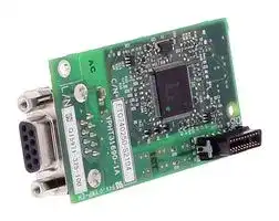


SI-P3
Option Card, PROFIBUS, AC Drive
- Manufacturer: OMRON INDUSTRIAL AUTOMATION
- Product type: Controller Accessories
- SVHC: To Be Advised
| Delivery and price | |
|---|---|
| Units per pack | 1 |
| Price | 394.5 € |
| Current stock | 10+ |
| Lead time | 30 days |
**==> picture [69 x 516] intentionally omitted <==**
## YASKAWA AC Drive Option PROFIBUS-DP Installation Manual
Type: SI-P3
To properly use the product, read this manual thoroughly and retain for easy reference, inspection, and maintenance. Ensure the end user receives this manual.
## 安川インバータ オプション PROFIBUS-DP通信 取扱説明書
> 形 式 SI-P3
製品を安全にお使いいただくために,この取扱説明書を必ずお読みください。 また,本書をお手元に保管していただくとともに,最終的に本製品をご使用になる ユーザー様のお手元に確実に届けられるよう,お取り計らい願います。
MANUAL NO. TOBP C730600 82D
## **Copyright © 2016 YASKAWA ELECTRIC CORPORATION**
All rights reserved. No part of this publication may be reproduced, stored in a retrieval system, or transmitted, in any form or by any means, mechanical, electronic, photocopying, recording, or otherwise, without the prior written permission of Yaskawa. No patent liability is assumed with respect to the use of the information contained herein. Moreover, because Yaskawa is constantly striving to improve its high-quality products, the information contained in this manual is subject to change without notice. Every precaution has been taken in the preparation of this manual. Yaskawa assumes no responsibility for errors or omissions. Neither is any liability assumed for damages resulting from the use of the information contained in this publication.
**YASKAWA ELECTRIC** TOBP C730600 82D YASKAWA AC Drive Option SI-P3 Installation Manual
**2**
## **Table of Contents**
|**1**|**PREFACE AND SAFETY . . . . . . . . . . . . . . . . . . . . . . . . . . .4**|
|---|---|
|**2**|**OVERVIEW . . . . . . . . . . . . . . . . . . . . . . . . . . . . . . . . . . . . . .9**|
|**3**|**RECEIVING. . . . . . . . . . . . . . . . . . . . . . . . . . . . . . . . . . . . .10**|
|**4**|**OPTION COMPONENTS . . . . . . . . . . . . . . . . . . . . . . . . . .11**|
|**5**|**INSTALLATION PROCEDURE . . . . . . . . . . . . . . . . . . . . .15**|
|**6**|**RELATED PARAMETERS . . . . . . . . . . . . . . . . . . . . . . . . .36**|
|**7**|**PROFIBUS-DP OPTION DATA AND I/O MAPS . . . . . . . .40**|
|**8**|**TROUBLESHOOTING . . . . . . . . . . . . . . . . . . . . . . . . . . . .44**|
|**9**|**EUROPEAN STANDARDS. . . . . . . . . . . . . . . . . . . . . . . . .49**|
|**10 **|**SPECIFICATIONS . . . . . . . . . . . . . . . . . . . . . . . . . . . . . . .51**|
**YASKAWA ELECTRIC** TOBP C730600 82D YASKAWA AC Drive Option SI-P3 Installation Manual
**3**
**1 Preface and Safety**
## **1 Preface and Safety**
YASKAWA Electric supplies component parts for use in a wide variety of industrial applications. The selection and application of YASKAWA products remain the responsibility of the equipment designer or end user.
YASKAWA accepts no responsibility for the way its products are incorporated into the final system design. Under no circumstances should any YASKAWA product be incorporated into any product or design as the exclusive or sole safety control. Without exception, all controls should be designed to detect faults dynamically and fail safely under all circumstances. All products designed to incorporate a component part manufactured by YASKAWA must be supplied to the end user with appropriate warnings and instructions as to the safe use and operation of that part. Any warnings provided by YASKAWA must be promptly provided to the end user. YASKAWA offers an express warranty only as to the quality of its products in conforming to standards and specifications published in the manual. NO OTHER WARRANTY, EXPRESS OR IMPLIED, IS OFFERED. YASKAWA assumes no liability for any personal injury, property damage, losses, or claims arising from misapplication of its products.
## u **Applicable Documentation**
The following manuals are available for the option:
## **Option**
||**Option**|
|---|---|
|**YASKAWA AC Drive Option**<br>**PROFIBUS-DP Installation Manual**<br>**Manual No: TOBP C730600 82**<br>**(This book)**|This guide is packaged together with the product and contains<br>information necessary to install the option and set related drive<br>parameters.|
|**YASKAWA AC Drive Option**<br>**PROFIBUS-DP Technical Manual**<br>**Manual No: SIEP C730600 82**|The technical manual contains detailed information about the option.<br>Access the following sites to obtain the technical manual:<br>U.S.: http://www.yaskawa.com<br>Europe: http://www.yaskawa.eu.com<br>Japan: http://www.e-mechatronics.com<br>Other areas: Check the back cover of these manuals.<br>For questions, contact Yaskawa or a Yaskawa representative.|
**YASKAWA ELECTRIC** TOBP C730600 82D YASKAWA AC Drive Option SI-P3 Installation Manual
**4**
**1 Preface and Safety**
## **Yaskawa Drive**
Drive manuals contain basic installation and wiring information in addition to detailed parameter setting, fault diagnostic, and maintenance information. The most recent versions of these manuals are available for download on our documentation websites: **YASKAWA AC Drive Manuals** U.S.: http://www.yaskawa.com Europe: http://www.yaskawa.eu.com Japan: http://www.e-mechatronics.com Other areas: Check the back cover of these manuals. For questions, contact your local Yaskawa sales office or the nearest Yaskawa representative.
## u **Terms and Abbreviations**
**Note:** Indicates a supplement or precaution that does not cause drive damage. **Option:** YASKAWA AC Drive Option PROFIBUS-DP **Drive:** • YASKAWA AC Drive 1000-Series (A1000, U1000, Z1000U) • YASKAWA AC Drive GA700 • YASKAWA AC Drive GA800 **Keypad:** • LCD Operator for YASKAWA AC Drive 1000-Series
- LED Operator for YASKAWA AC Drive 1000-Series
- LCD Keypad for YASKAWA AC Drive GA700 and GA800
- LED Keypad for YASKAWA AC Drive GA700 and GA800
**V/f:** V/f Control **OLV:** Open Loop Vector Control **CLV:** Closed Loop Vector Control **AOLV:** Advanced Open Loop Vector Control **OLV/PM:** Open Loop Vector Control for PM **AOLV/PM:** Advanced Open Loop Vector Control for PM **CLV/PM:** Closed Loop Vector Control for PM **EZOLV:** EZ Open Loop Vector Control
## u **Registered Trademarks**
- PROFIBUS-DP is a registered trademark of PROFIBUS and PROFINET International.
- Trademarks are the property of their respective owners.
**YASKAWA ELECTRIC** TOBP C730600 82D YASKAWA AC Drive Option SI-P3 Installation Manual
**5**
**1 Preface and Safety**
## u **Supplemental Safety Information**
Read and understand this manual before installing, operating, or servicing this option. Install the option according to this manual and local codes.
The following conventions indicate safety messages in this manual. Failure to heed these messages could cause fatal injury or damage products and related equipment and systems.
## **DANGER**
**Indicates a hazardous situation, which, if not avoided, will cause death or serious injury** .
## **W ARNING**
**Indicates a hazardous situation, which, if not avoided, could cause death or serious injury.**
## **CAUTION**
**Indicates a hazardous situation, which, if not avoided, could cause minor or moderate injury.**
## **NOTICE**
**Indicates an equipment damage message.**
**YASKAWA ELECTRIC** TOBP C730600 82D YASKAWA AC Drive Option SI-P3 Installation Manual
**6**
**1 Preface and Safety**
## n **General Safety**
## **General Precautions**
- The diagrams in this book may include options and drives without covers or safety shields to illustrate details. Be sure to reinstall covers or shields before operating any devices. Use the option according to the instructions described in this manual.
- The diagrams in this manual are provided as examples only and may not pertain to all products covered by this manual.
- The products and specifications described in this manual or the content and presentation of the manual may be changed without notice to improve the product and/or the manual.
- Contact Yaskawa or a Yaskawa representative and provide the manual number shown on the front cover to order new copies of the manual.
## **DANGER**
**Heed the safety messages in this manual.**
Failure to comply will cause death or serious injury.
The operating company is responsible for any injuries or equipment damage resulting from failure to heed the warnings in this manual.
## **W ARNING**
## **Electrical Shock Hazard**
**Do not attempt to modify or alter the drive or drive circuitry in any way not explained in this manual.**
Failure to comply could cause death or serious injury and will void warranty. Yaskawa is not responsible for any modification of the product made by the user. Do not modify this product.
**YASKAWA ELECTRIC** TOBP C730600 82D YASKAWA AC Drive Option SI-P3 Installation Manual
**7**
**1 Preface and Safety**
## **NOTICE**
## **Do not modify the drive or option circuitry.**
Failure to comply could result in damage to the drive or option and will void warranty. Yaskawa is not responsible for any modification of the product made by the user.
**Do not expose the drive or the option to halogen group disinfectants. Do not pack the drive or the option in fumigated or sterilized wooden materials. Do not sterilize the entire package after packing the product.**
Failure to comply could damage electrical components in the option.
**YASKAWA ELECTRIC** TOBP C730600 82D YASKAWA AC Drive Option SI-P3 Installation Manual
**8**
**2 Overview**
## **2 Overview**
The SI-P3 PROFIBUS-DP Option is an open digital communication system supporting a wide range of fast, time-critical applications.
PROFIBUS Decentralized Periphery (PROFIBUS-DP) is one of the three PROFIBUS variants. DP is dedicated to fast data communication between systems and peripherals at a field level. This option connects a Yaskawa drive to a field network using the PROFIBUS-DP protocol.
PROFIBUS-DP is included into the European Fieldbus Standard EN 50170.
The network is primarily used in process and factory automation.
Install the option/PROFIBUS option on a drive to perform the following functions from a PROFIBUS-DP master device:
- Operate the drive
- Monitor the drive operation status
- Change drive parameter settings
## u **Compatible Products**
The option can be used with the products in _**Table 1**_ .
**Table 1 Compatible Products**
|**Product Series**|**Model(s)**|
|---|---|
|A1000|All models|
|U1000|All models|
|Z1000U|All models|
|GA700|All models|
|GA800|All models|
**Note:** For Yaskawa customers in the North or South America region: If your product is not listed in _**Table 1**_ , refer to the web page below to confirm this manual is correct for your product. The web page provides a list of option manuals by product, and a direct link to download a PDF.
## **Scan QR code**
**Or refer to:** _http://www.yaskawa.com/optionlookup_
**YASKAWA ELECTRIC** TOBP C730600 82D YASKAWA AC Drive Option SI-P3 Installation Manual
**9**
**3 Receiving**
## **3 Receiving**
After receiving the option package:
1. Make sure that the option is not damaged and no parts are missing. Contact your sales outlet if the option or other parts appear damaged.
**NOTICE:** _Do not use damaged parts to connect the drive and the option. Failure to comply could damage the drive and option._
2. Confirm that the model number on the option nameplate and the model listed in the purchase order are the same. Refer to _**Figure 1**_ on page _**11**_ for details. Contact the distributor where the option was purchased or contact Yaskawa or a Yaskawa representative about any problems with the option.
## u **Contents and Packaging**
## **Table 2 Contents of Package**
**==> picture [333 x 100] intentionally omitted <==**
**----- Start of picture text -----**<br>
Ground LED Labels<br>Screws Installation<br>Description: Option Wire <1> (M3) 1000-Series GA700 and GA800 Manual<br>MANUAL<br>– ERR RUN<br>BF COMM<br>Quantity: 1 1 3 <2> 1 1 1<br>**----- End of picture text -----**<br>
- <1> GA700 and GA800 drives do not use the ground wire.
- <2> GA700 and GA800 drives use two screws only.
## u **Installation Tools**
- A Phillips screwdriver. Phillips screw sizes vary by drive capacity.
- A flat-blade screwdriver (blade depth: 0.4 mm (0.02 in), width: 2.5 mm (0.1 in)).
- A pair of diagonal cutting pliers.
- A small file or medium-grit sandpaper.
**YASKAWA ELECTRIC** TOBP C730600 82D YASKAWA AC Drive Option SI-P3 Installation Manual
**10**
**4 Option Components**
## **4 Option Components**
## u **PROFIBUS-DP Option**
**==> picture [309 x 109] intentionally omitted <==**
**----- Start of picture text -----**<br>
H I A<br>SI-P3<br>B<br>Underside<br>C<br>D<br>Communication connector<br>G FE<br>bottom view<br>**----- End of picture text -----**<br>
- **A – Connector (CN5)**
- **B – Installation hole**
- **F – LED (ERR)** _**<1>**_
- **G – Ground terminal (FE) and installation hole** _**<2>**_
- **C – LED (RUN)** _**<1>**_ **H – Communication cable connector (CN4)**
- **D – LED (COMM)** _**<1>**_
- **I – Option model number**
- **E – LED (BF)** _**<1>**_
- <1> _**Refer to Option LED Display on page 12**_ for details on the LEDs
- <2> Connect the provided ground wire during installation. Installation on GA700 and GA800 drives does not require the ground wire.
## **Figure 1 PROFIBUS-DP Option Components**
**YASKAWA ELECTRIC** TOBP C730600 82D YASKAWA AC Drive Option SI-P3 Installation Manual
**11**
**4 Option Components**
## u **Communication Connector**
The option has a 9-pin D-sub connector to connect to a PROFIBUS network.
## **Table 3 Communication Connector (9-pin D-sub)**
||**Connector**|**Connector**|**Connector**|**Pin**|**Signal**|**Description**|
|---|---|---|---|---|---|---|
|1<br>5<br>2<br>3<br>4|||6<br>9<br>7<br>8|1|Shield|Connected to the metal-shell (no direct FG-connection)|
|||||2|–|–|
||||||||
|||||3|RxD/TxD-P|Receive/Transmit data; line B (red)|
|||||4<br>5|CNTR-P<br>DGND|Control signal for repeaters (direction control)<br>Data rnd (rfrn lta t VP)|
||||||||
|||||6|VP|gou eeece voge o<br>Power supply output for bus termination (for termination resistor)|
||||||||
|||||7|–|–|
|||||8|RxD/TxD-N|Receive/Transmit data; line A (green)|
||||||||
|||||9|–|–|
## u **Option LED Display**
**==> picture [69 x 23] intentionally omitted <==**
**----- Start of picture text -----**<br>
ERR RUN<br>BF COMM<br>**----- End of picture text -----**<br>
**==> picture [35 x 51] intentionally omitted <==**
**----- Start of picture text -----**<br>
RUN COMM<br>ERR BF<br>**----- End of picture text -----**<br>
1000-Series Label GA700 and GA800 Label
## **Figure 2 Option LED Labels**
The option has four bicolor, red/green LEDs to relay information about power, communication status, and errors.
The operational states of the LEDs after completion of the power-up diagnostic process are described in _**Table 5**_ . Wait at least 2 seconds for the power-up diagnostic process to complete before verifying the states of the LEDs.
**YASKAWA ELECTRIC** TOBP C730600 82D YASKAWA AC Drive Option SI-P3 Installation Manual
**12**
**4 Option Components**
## **Table 4 Option LED States**
|**LED**|**Display**|**Display**|**Operating**<br>**Status**|**Description**|
|---|---|---|---|---|
||**Color**|**Status**|||
|**RUN**<br>**(Power)**|Green|ON|Power supply<br>ON|Power is supplied to the option, and the option hardware<br>self-diagnostics check is complete.|
|||OFF|Power supply<br>OFF|• The drive has no power supply.<br>• Option and drive are not connected properly and/or no<br>power is supplied to the option.<br>• An internal, self-diagnostic error occurred in the option.|
|**ERR**<br>**(Option Error)**|Red|ON|Option error|Self-diagnostics error occurred in the option.|
|||Flashing|Drive connection<br>error|Connection error between option and drive. This includes<br>node address setting errors to parameter F6-30 on the drive<br>side.|
|||OFF|Normal<br>operation|Drive and option are properly connected.|
|**COMM**<br>**(Communication**<br>**Status)**|<br>Green|ON|Communication<br>connected|Normal send/receive between the option and the<br>PROFIBUS-DP master.|
|||OFF|No data<br>exchange|There is a problem establishing communication between<br>the option and the PROFIBUS-DP master.|
|**BF**<br>**(PROFIBUS-DP**<br>**Error)**|Red|ON|Waiting for<br>communication<br>procedure setting|Communication-related parameters are in the process of<br>being set or initialized by the PROFIBUS-DP master.|
|||Flashing|Communication<br>setting error|Communication parameter error from PROFIBUS-DP<br>master.|
|||OFF|Normal<br>operation|LED shuts off when the PROFIBUS-DP master is finished<br>setting communication-related parameters.|
**YASKAWA ELECTRIC** TOBP C730600 82D YASKAWA AC Drive Option SI-P3 Installation Manual
**13**
**4 Option Components**
**Table 5 LED Operation After Power-up Diagnostic**
|**LED**|**LED**|**LED**|**LED**|**Communication**<br>**Status**|**Possible Cause**|**Solution**|
|---|---|---|---|---|---|---|
|**RUN**|**ERR**|**COMM**|**BF**||||
|●|●|●|●|No power|Drive has no power.|Check all wiring to the drive, then<br>turn on the power.|
||||||Option is not properly<br>connected to the drive or is<br>not receiving enough power.|Shut off the drive and make sure<br>the option is connected properly.<br>Turn the power back on.|
|○|●|●|●|• Checking<br>connection with<br>the drive<br>• Waiting for data<br>from the master|• Option is reading the node<br>address or parameter<br>configuration.<br>• Waiting for initial input<br>data from master device.|–|
|●|○|●|●|Option<br>self-diagnostics<br>error|The option is damaged.|Cycle power to the drive. If the<br>LED status does not change,<br>replace the option.|
|●||●|●|Problem<br>connecting to the<br>drive|• Problem initializing the<br>drive and the option.<br>• Incorrect node address.|• Cycle power to the drive. If the<br>LED status does not change,<br>replace the option.<br>• Check the node address setting in<br>the drive (F6-30).|
|○|●|●|○|Waiting for data<br>from the master<br>device|Waiting for data from the<br>master device.<br>(Set_Parm_Message or<br>Chk_Cfg_Message)|• Check master network settings.<br>• Make sure the master device is<br>operating normally.<br>• Check the terminal resistance<br>settings on the data line.<br>• Check for problems with the data<br>line and connector.<br>• Check if the data line is<br>connected properly to<br>communication connector CN5.|
|○|●|●||Incorrect data or<br>option time out<br>waiting for data|The communication settings<br>in the master are set<br>incorrectly.|Check the communication settings<br>in the master.|
|○|●|○|●|Sending or<br>receiving data|–|–|
: On / : Flashing / : Off
**YASKAWA ELECTRIC** TOBP C730600 82D YASKAWA AC Drive Option SI-P3 Installation Manual
**14**
**5 Installation Procedure**
## **5 Installation Procedure**
## u **Section Safety**
## **DANGER**
## **Electric Shock Hazard**
**Do not inspect, connect, or disconnect any wiring while the drive is energized.**
Failure to comply will cause death or serious injury.
Before servicing, disconnect all power to the equipment and wait for at least the time specified on the warning label. The internal capacitor remains charged even after the drive is de-energized. The charge indicator LED will extinguish when the DC bus voltage is below 50 Vdc. When all indicators are OFF, measure for unsafe voltages to confirm the drive is safe.
## **W ARNING**
## **Electrical Shock Hazard**
**Do not operate equipment with covers removed.**
Failure to comply could cause death or serious injury.
The diagrams in this section may include options and drives without covers or safety shields to illustrate details. Reinstall covers and shields before operating the drive and run the drive according to the instructions described in this manual.
**Do not allow unqualified personnel to perform work on the drive or option.**
Failure to comply could cause death or serious injury.
Only authorized personnel familiar with installation, adjustment, and maintenance of AC drives and options may perform work.
**Do not remove covers or touch circuit boards while the drive is energized.**
Failure to comply could cause death or serious injury.
**YASKAWA ELECTRIC** TOBP C730600 82D YASKAWA AC Drive Option SI-P3 Installation Manual
**15**
**5 Installation Procedure**
## **W ARNING**
**Do not use damaged wires, stress the wiring, or damage the wire insulation.**
Failure to comply could cause death or serious injury.
## **Fire Hazard**
**Tighten all terminal screws to the specified tightening torque.**
Loose or overtightened connections could cause erroneous operation and damage to the terminal block or start a fire and cause death or serious injury.
## **NOTICE**
**Damage to Equipment Observe proper electrostatic discharge (ESD) procedures when handling the option, drive, and circuit boards.**
Failure to comply could cause ESD damage to circuitry.
**Never connect or disconnect the motor from the drive while the drive is outputting voltage.** Improper equipment sequencing could damage the drive.
**Do not connect or operate any equipment with visible damage or missing parts.** Failure to comply could further damage the equipment.
**Do not use unshielded wire for control wiring.**
Failure to comply may cause electrical interference resulting in poor system performance. Use shielded, twisted-pair wires and ground the shield to the ground terminal of the drive. **Properly connect all pins and connectors on the option and drive.** Failure to comply could prevent proper operation and damage equipment. **Confirm that all connections are correct after installing the option and connecting peripheral devices.** Failure to comply could damage the option.
**YASKAWA ELECTRIC** TOBP C730600 82D YASKAWA AC Drive Option SI-P3 Installation Manual
**16**
**5 Installation Procedure**
## u **Procedures for Installing and Wiring Options on a Drive**
Procedures for installing and wiring options differ depending on the drive model. Refer to _**Table 6**_ to check the procedures for installing and wiring options on a drive.
**Table 6 Procedures for Installing and Wiring Options on a Drive**
|**Product Series**|**Procedures for Installing and**<br>**Wiring Options on a Drive**|**Page**|
|---|---|---|
|A1000|Procedure A|**_18_**|
|U1000|Procedure A|**_18_**|
|Z1000U|Procedure A|**_18_**|
|GA700|Procedure B|**_24_**|
|GA800|Procedure B|**_24_**|
**YASKAWA ELECTRIC** TOBP C730600 82D YASKAWA AC Drive Option SI-P3 Installation Manual
**17**
**5 Installation Procedure**
## n **Procedure A**
This section shows the procedure to install and wire the option on a 1000-series drive.
## **Prepare the Drive for the Option**
1. Correctly wire the drive as specified by the manual packaged with the drive.
2. Make sure that the drive functions correctly.
- Refer to _**Figure 3**_ for an exploded view of the drive with the option and related components for reference in the installation procedure.
**==> picture [324 x 258] intentionally omitted <==**
**----- Start of picture text -----**<br>
A<br>M<br>B C<br>L<br>D<br>K<br>J<br>E<br>ERR RUN<br>I BF COMM<br>H<br>G<br>F<br>A – Insertion point for CN5 I – Ground wire<br>B – Option card J – Drive grounding terminal (FE)<br>C – Front cover K – Connector CN5-A<br>D – Keypad L – Connector CN5-B<br>E – LED label (Not available for communication<br>F – Terminal cover option installation.)<br>G – Removable tabs for wire routing M – Connector CN5-C<br>H – Included screws (Not available for communication<br>**----- End of picture text -----**<br>
- **M – Connector CN5-C (Not available for communication option installation.)**
**Figure 3 Drive Components with Option**
**YASKAWA ELECTRIC** TOBP C730600 82D YASKAWA AC Drive Option SI-P3 Installation Manual
**18**
**5 Installation Procedure**
## **Install the Option**
Refer to the instructions below to install the option.
- **Note:** Refer to the instruction manual of a specific drive for information on removing and installing the keypads and the covers.
**DANGER!** _Electrical Shock Hazard. Do not inspect, connect, or disconnect any wiring while the drive is energized. Failure to comply will cause death or serious injury. Before servicing, disconnect all power to the equipment and wait for at least the time specified on the warning label. The internal capacitor remains charged even after the drive is de-energized. The charge indicator LED will extinguish when the DC bus voltage is below 50 Vdc. When all indicators are OFF, measure for unsafe voltages to confirm the drive is safe._
**1.** Shut off power to the drive, wait the appropriate amount of time for voltage to dissipate, then remove the keypad (D) and front covers (C, F). Refer to the manual packaged with the drive for details on keypad and cover removal.
**NOTICE:** _Damage to Equipment. Observe proper electrostatic discharge (ESD) procedures when handling the option, drive, and circuit boards. Failure to comply could cause ESD damage to circuitry._
**==> picture [195 x 154] intentionally omitted <==**
**----- Start of picture text -----**<br>
C<br>D<br>F<br>**----- End of picture text -----**<br>
**Figure 4 Remove the Keypad, Front Cover, and Terminal Cover**
**YASKAWA ELECTRIC** TOBP C730600 82D YASKAWA AC Drive Option SI-P3 Installation Manual
**19**
**5 Installation Procedure**
**2.** Affix the LED label (E) in the appropriate position on the drive front cover (C).
**==> picture [215 x 146] intentionally omitted <==**
**----- Start of picture text -----**<br>
C<br>E<br>ERR RUN<br>BF COMM<br>**----- End of picture text -----**<br>
**Figure 5 Affix the LED Label**
**3.** Insert the option card (B) into the CN5-A (K) connector on the drive and fasten it into place using one of the included screws (H). Tighten the screw to 0.5 to 0.6 Nm (4.4 to 5.3 inlb).
**==> picture [205 x 184] intentionally omitted <==**
**----- Start of picture text -----**<br>
B<br>K<br>H<br>**----- End of picture text -----**<br>
**Figure 6 Insert the Option Card**
**YASKAWA ELECTRIC** TOBP C730600 82D YASKAWA AC Drive Option SI-P3 Installation Manual
**20**
**5 Installation Procedure**
**4.** Connect one end of the ground wire (I) to the ground terminal (J) using one of the remaining provided screws (H). Connect the other end of the ground wire (I) to the remaining ground terminal using the last remaining provided screw (H).
**==> picture [231 x 179] intentionally omitted <==**
**----- Start of picture text -----**<br>
J<br>I<br>H<br>BF<br>**----- End of picture text -----**<br>
**Figure 7 Connect the Ground Wire**
**Note:** The drive has only two ground terminal screw holes (J). Two ground wires should share the same ground terminal when connecting three options.
**YASKAWA ELECTRIC** TOBP C730600 82D YASKAWA AC Drive Option SI-P3 Installation Manual
**21**
**5 Installation Procedure**
**5.** Select the proper PROFIBUS-DP dedicated communication cable according to _**Table 7**_ and _**Table 8**_ .
Route the option wiring inside the enclosure as shown in _**Figure 8**_ -B. Take proper precautions so that the front covers will easily fit back onto the drive. Users may also choose to route the option wiring through openings on the front cover of some models. Remove the perforated tabs on the left side of the front cover as shown in _**Figure 8**_ -A to create the necessary openings on these models. Refer to the Peripheral Devices & Options section of the drive instruction manual for more information.
**==> picture [311 x 207] intentionally omitted <==**
**----- Start of picture text -----**<br>
A<br>B<br>A – Route wires through the openings B – Use the open space provided<br>provided on the left side of the inside the drive to route option<br>front cover. <1> wiring.<br>**----- End of picture text -----**<br>
- <1> The drive will not meet Enclosed wall-mounted type (IP20/UL Type 1) requirements if wiring is exposed outside the enclosure.
## **Figure 8 Wire Routing Examples**
**YASKAWA ELECTRIC** TOBP C730600 82D YASKAWA AC Drive Option SI-P3 Installation Manual
**22**
**5 Installation Procedure**
**6.** Firmly connect the PROFIBUS-DP communication cable to option communication connector CN4.
- Install PROFIBUS-DP communications cables apart from main-circuit wiring and other electrical and power lines. Ensure the cable end is firmly connected (see _**Figure 18**_ ). Refer to _**Communication Cable Specifications on page 32**_ for details.
**7.** Reattach the drive front covers (C, F) and the keypad (D).
**NOTICE:** _Do not pinch cables between the front covers and the drive. Failure to comply could cause erroneous operation._
**==> picture [222 x 169] intentionally omitted <==**
**----- Start of picture text -----**<br>
C<br>D<br>F<br>**----- End of picture text -----**<br>
**Figure 9 Replace the Front Covers and Keypad**
**8.** Set drive parameters in _**Table 9**_ for correct option performance. Be sure to set parameter F6-30 to a node address unique to the network.
**YASKAWA ELECTRIC** TOBP C730600 82D YASKAWA AC Drive Option SI-P3 Installation Manual
**23**
**5 Installation Procedure**
## n **Procedure B**
This section shows the procedure to install and wire the option on a GA700 or GA800 drive.
## **Prepare the Drive for the Option**
1. Correctly wire the drive as specified by the manual packaged with the drive.
2. Make sure that the drive functions correctly.
- Refer to _**Figure 10**_ for an exploded view of the drive with the option and related components for reference in the installation procedure.
**==> picture [274 x 176] intentionally omitted <==**
**----- Start of picture text -----**<br>
A1000<br>A<br>B<br>C A1000 E<br>D<br>J<br>F<br>I<br>H<br>G<br>**----- End of picture text -----**<br>
- **A – Insertion point for CN5 connector**
- **B – SI-P3 option**
- **C – Included screws**
- **D – Drive front cover**
- **E – LED label**
- **F – Keypad**
- **G – LED Status Ring board**
- **H – Connector CN5-A**
- **I – Connector CN5-B (Not available for communication option installation.)**
- **J – Connector CN5-C**
- **(Not available for communication option installation.)**
## **Figure 10 Drive Components with Option**
**YASKAWA ELECTRIC** TOBP C730600 82D YASKAWA AC Drive Option SI-P3 Installation Manual
**24**
**5 Installation Procedure**
## **Install the Option**
Remove the front cover of the drive before you install the option. Refer to the drive manual for information about how to remove the front cover. Different drive sizes have different cover removal procedures.
You can only install this option into the **CN5-A** connector on the drive control board.
**DANGER!** _Electrical Shock Hazard. Do not inspect, connect, or disconnect any wiring while the drive is energized. Failure to comply will cause death or serious injury. Before servicing, disconnect all power to the equipment and wait for at least the time specified on the warning label. The internal capacitor remains charged even after the drive is de-energized. The charge indicator LED will extinguish when the DC bus voltage is below 50 Vdc. When all indicators are OFF, measure for unsafe voltages to confirm the drive is safe._
**1.** Affix the LED label (E) in the appropriate position on the drive front cover (D).
**==> picture [160 x 142] intentionally omitted <==**
**----- Start of picture text -----**<br>
E<br>D<br>A1000<br>**----- End of picture text -----**<br>
**Figure 11 Affix the LED Label**
**YASKAWA ELECTRIC** TOBP C730600 82D YASKAWA AC Drive Option SI-P3 Installation Manual
**25**
**5 Installation Procedure**
**2.** Shut off power to the drive, wait the appropriate amount of time for voltage to dissipate, then remove the front cover (D). Refer to the manual packaged with the drive for details on cover removal.
**NOTICE:** _Damage to Equipment. Observe proper electrostatic discharge (ESD) procedures when handling the option, drive, and circuit boards. Failure to comply could cause ESD damage to circuitry._
**==> picture [233 x 210] intentionally omitted <==**
**----- Start of picture text -----**<br>
Move the keypad connector to the holder on the<br>A1000 drive after removing the keypad and before removing<br>the front cover. Insert the keypad connector tab into<br>the holder when installing the keypad connector to<br>the holder.<br>Holder<br>Keypad connector tab<br>Keypad connector<br>**----- End of picture text -----**<br>
**Figure 12 Remove the Front Cover and Keypad**
**YASKAWA ELECTRIC** TOBP C730600 82D YASKAWA AC Drive Option SI-P3 Installation Manual
**26**
**5 Installation Procedure**
**3.** Carefully remove the LED Status Ring board (G) and place it on the right side of the drive using the temporary placement holes.
Refer to the manual packaged with the drive for details on removing the LED Status Ring board.
**NOTICE:** _Do not remove the LED Status Ring board cable connector. Failure to comply could cause erroneous operation and damage the drive._
**==> picture [266 x 121] intentionally omitted <==**
**----- Start of picture text -----**<br>
G<br>Temporary placement holes<br>A1000<br>Drive front view<br>**----- End of picture text -----**<br>
**Figure 13 Remove the LED Status Ring Board**
**YASKAWA ELECTRIC** TOBP C730600 82D YASKAWA AC Drive Option SI-P3 Installation Manual
**27**
**5 Installation Procedure**
**4.** Insert the option card (B) into the CN5-A connector (H) on the drive and fasten it into place using the included screws (C). Tighten both screws to 0.5 to 0.6 Nm (4.4 to 5.3 inlb).
**Note:** Installing the option card on GA700 and GA800 drives requires only two screws and does not require a ground wire. The option package ships with three screws and a ground wire for installation on other product series. Do not use the ground wire or the extra screw.
**==> picture [249 x 177] intentionally omitted <==**
**----- Start of picture text -----**<br>
A1000<br>B<br>C<br>H<br>**----- End of picture text -----**<br>
**Figure 14 Insert the Option Card**
**YASKAWA ELECTRIC** TOBP C730600 82D YASKAWA AC Drive Option SI-P3 Installation Manual
**28**
**5 Installation Procedure**
**5.** Confirm proper option wiring.
Depending on the drive model, some drives may require routing the wiring to the outside as shown in _**Figure 15**_ .
Route the wiring inside the enclosure through the lower wiring cover to the outside as shown in _**Figure 16**_ for the drives that do not require routing the wiring to the outside.
**==> picture [142 x 178] intentionally omitted <==**
**Figure 15 Wire Routing Examples**
**==> picture [135 x 182] intentionally omitted <==**
**----- Start of picture text -----**<br>
Wiring cover<br>**----- End of picture text -----**<br>
**Figure 16 Wire Routing Examples**
**6.** Select the proper PROFIBUS-DP dedicated communication cable according to _**Table 7**_ and _**Table 8**_ .
- Firmly connect the PROFIBUS-DP communication cable to option communication connector CN4.
Install PROFIBUS-DP communications cables apart from main-circuit wiring and other electrical and power lines. Ensure the cable end is firmly connected (see _**Figure 18**_ ). Refer to _**Communication Cable Specifications on page 32**_ for details.
**Note:** Maximum transmission distance is 100 m (328 ft). Minimum wiring distance between stations is 0.2 m (7.9 in).
**7.** After you connect the prepared cable for the 9-pin D-sub communication connector CN5, make sure that the option wire routing from Step _**6.**_ is correct.
**YASKAWA ELECTRIC** TOBP C730600 82D YASKAWA AC Drive Option SI-P3 Installation Manual
**29**
**5 Installation Procedure**
## **8.** Reattach the LED Status Ring board (G).
- Use the open space provided inside the LED Status Ring board to route option wiring.
**NOTICE:** _Do not pinch cables between the front cover or the LED Status Ring board and the drive. Failure to comply could cause erroneous operation._
## **9.** Reattach the drive front cover (D) and the keypad (F).
**==> picture [240 x 228] intentionally omitted <==**
**----- Start of picture text -----**<br>
Install the keypad to the drive after replacing A1000<br>the keypad connector and then the keypad<br>connector. At that time, insert the keypad<br>connector tab into the drive.<br>Tab<br>Keypad<br>connector<br>D<br>F<br>G<br>**----- End of picture text -----**<br>
**Figure 17 Replace the Front Cover and Keypad**
**YASKAWA ELECTRIC** TOBP C730600 82D YASKAWA AC Drive Option SI-P3 Installation Manual
**30**
**5 Installation Procedure**
**Note:** Depending on the drive model, some drives may require replacing the front cover of the drive after routing the wiring to the outside. In these cases, use diagonal cutters to cut out the perforated openings in the right side of the drive front cover and leave no sharp edges to damage wiring.
The drive will not meet IP20 conformity if wiring is exposed outside the enclosure.
**==> picture [143 x 43] intentionally omitted <==**
**----- Start of picture text -----**<br>
Perforated<br>openings cut out<br>Cut out here.<br>**----- End of picture text -----**<br>
**==> picture [70 x 103] intentionally omitted <==**
Right side of the drive front cover Route the wiring and connector to the outside.
**10.** Set drive parameters in _**Table 9**_ for correct option performance. Be sure to set parameter F6-30 to a node address unique to the network.
**YASKAWA ELECTRIC** TOBP C730600 82D YASKAWA AC Drive Option SI-P3 Installation Manual
**31**
**5 Installation Procedure**
## u **Communication Cable Specifications**
To ensure proper performance, Yaskawa recommends using PROFIBUS-DP-dedicated cables. Refer to the PROFIBUS-DP website at www.profibus.com for more information on cables.
Yaskawa recommends using PROFIBUS-DP cables suitable for the conditions listed in _**Table 7**_ and _**Table 8**_ .
**Table 7 Communication Cable Requirements**
|**Condition**|**Specifications**|
|---|---|
|**Impedance**|135 to 165Ωat a frequency of (3 to 20 MHz)|
|**Capacity**|30 pF/m maximum|
|**Loop Resistance**|110Ω/km maximum|
|**Core Cross-Section**|0.34 mm2minimum|
|**Core Diameter**|0.64 mm minimum|
**Table 8 Communication Cable Length**
|**Communication Speed (kbps)**|**Distance per Segment**|
|---|---|
|9.6|1200 m (3937 ft)|
|19.2|1200 m (3937 ft)|
|45.45|1200 m (3937 ft)|
|93.75|1200 m (3937 ft)|
|187.5|1000 m (3280 ft)|
|500|400 m (1312 ft)|
|1500|200 m (656 ft)|
|3000|100 m (328 ft)|
|6000|100 m (328 ft)|
|12000|100 m (328 ft)|
**YASKAWA ELECTRIC** TOBP C730600 82D YASKAWA AC Drive Option SI-P3 Installation Manual
**32**
**5 Installation Procedure**
## u **Option Connection Diagram**
**==> picture [330 x 125] intentionally omitted <==**
**----- Start of picture text -----**<br>
Drive<br>PROFIBUS Cable PROFIBUS Cable Connector<br>CN5-A<br>(Red) 1B B-line 3<br>To PROFIBUS-DPMaster (Green) 1A A-line 8 FE <1><br>RTS 4<br>(Red) 2B VP 6 SI-P3<br>To the next slave (Green) 2A<br>DGND 5<br>(Shell) (Shell)<br>9-pin D-sub Connector<br>Turn on the termination resistor<br>switch for the last node on the bus<br>**----- End of picture text -----**<br>
**Figure 18 Option Connection Diagram**
- <1> Connect the provided ground wire for installations on 1000-series drives. The ground wire is not necessary for installation on GA700 or GA800 drives.
**YASKAWA ELECTRIC** TOBP C730600 82D YASKAWA AC Drive Option SI-P3 Installation Manual
**33**
**5 Installation Procedure**
## n **PROFIBUS-DP Termination**
The option does not have a built-in termination resistor. The termination resistance must be set on the final drive in the network using a switch on the 9-pin D-sub connector. Make sure that only the connector for the final drive in the network has a termination resistor; communication problems may arise if any other network drive has a termination resistor.
Use only the input side cable entry as shown in _**Figure 19**_ when connecting both ends of the network. Most 9-pin D-sub connectors have a function for disconnecting the output side of the cable. Communication will not be possible between devices if the connector is reversed. Most connectors have arrows indicating the input and output sides.
**==> picture [159 x 205] intentionally omitted <==**
**----- Start of picture text -----**<br>
9-pin D-sub Connector<br>Bus termination<br>Switch O ON<br>O O OFF<br>Incoming Cable Outgoing Cable<br>**----- End of picture text -----**<br>
**Figure 19 PROFIBUS Cable Connection with Termination Resistors**
**Bus termination ON** = incoming and outgoing cables not connected. **Bus termination OFF** = incoming and outgoing cables connected.
**YASKAWA ELECTRIC** TOBP C730600 82D YASKAWA AC Drive Option SI-P3 Installation Manual
**34**
**5 Installation Procedure**
Termination resistors without inductors as shown in _**Figure 20**_ can only be used for baud rates below 1.5 Mbps. Baud rates 1.5 Mbps and higher require termination with resistors and inductors as shown in _**Figure 18**_ .
**==> picture [116 x 168] intentionally omitted <==**
**----- Start of picture text -----**<br>
VP (pin 6)<br>390 Ω<br>B - Data line<br>RxD/TxD-P (pin 3)<br>220 Ω<br>A - Data line<br>RxD/TxD-N (pin 8)<br>390 Ω<br>DGND (pin 5)<br>**----- End of picture text -----**<br>
**Figure 20 Cable Termination of the Option Cable to EN50170 (Pin Numbers for a 9-pin D-sub Connector)**
## u **GSD Files**
To facilitate network implementation, obtain a GSD file from one of the following websites depending on your region:
U.S.: http://www.yaskawa.com
Europe: http://www.yaskawa.eu.com
Japan: http://www.e-mechatronics.com
Other areas: Check the back cover of these manuals.
For questions, contact Yaskawa or a Yaskawa representative.
**YASKAWA ELECTRIC** TOBP C730600 82D YASKAWA AC Drive Option SI-P3 Installation Manual
**35**
**6 Related Parameters**
## **6 Related Parameters**
The parameters in _**Table 9**_ set the drive for operation with the option. Confirm proper setting of all parameters in _**Table 9**_ before starting network communications. Refer to the manual packaged with the drive for details on setting parameters.
**Note:** Hex.: MEMOBUS addresses that you can use to change parameters over network communication are represented in hexadecimal numbers.
**Table 9 Related Parameters**
|**No.**<br>**(Hex.)**|**Name**|**Description**|**Values**|
|---|---|---|---|
|b1-01<br>(0180)<br>**_<1>_**|Reference 1 Source|Selects the input method for frequency reference.<br>0: Keypad<br>1: Analog Input<br>2: Memobus/Modbus Communications<br>3: Option PCB<br>4: Pulse Train Input|Default: 1<br>Range: 0 to 4<br>(Set to 3)|
|b1-02<br>(0181)<br>**_<1>_**|Run Command 1 Source|Selects the input method for the Run command.<br>0: Keypad<br>1: Digital Input<br>2: Memobus/Modbus Communications<br>3: Option PCB|Default: 1<br>Range: 0 to 3<br>(Set to 3)|
|d5-01<br>(029A)|Torque Control Selection|0: Speed Control<br>1: Torque Control|Default: 0<br>Range: 0, 1|
|F6-01<br>(03A2)<br>**_<2>_**|Communication Error<br>Selection|Selects drive response when a bUS error is detected<br>during communications with the option.<br>0: Ramp to Stop<br>1: Coast to Stop<br>2: Fast Stop (Use C1-09)<br>3: Alarm Only**_<2>_**<br>4: Alarm - Run at d1-04**_<2> <3>_**<br>5: Alarm - Ramp to Stop**_<3>_**|Default: 1<br>Range: 0 to 5**_<4>_**|
|F6-02<br>(03A3)|Comm External Fault (EF0)<br>Detect|Selects the condition for external fault detection<br>(EF0).<br>0: Always detected<br>1: Detection during run only|Default: 0<br>Range: 0, 1|
|F6-03<br>(03A4)|Comm External Fault (EF0)<br>Select|Selects drive response for external fault input (EF0)<br>detection during option communications.<br>0: Ramp to Stop<br>1: Coast to Stop<br>2: Fast Stop (Use C1-09)<br>3: Alarm Only**_<2>_**|Default: 1<br>Range: 0 to 3|
**YASKAWA ELECTRIC** TOBP C730600 82D YASKAWA AC Drive Option SI-P3 Installation Manual
**36**
**6 Related Parameters**
|**No.**<br>**(Hex.)**|**Name**|**Description**|**Values**|
|---|---|---|---|
|F6-06<br>(03A7)<br>**_<5>_**|Torque Reference/Limit by<br>Comm|Enabling this parameter allows d5-01 to determine<br>whether the value is read as the Torque Limit value<br>(d5-01 = 0) or the Torque Reference value (d5-01 =<br>1).<br>0: Disabled<br>1: Enabled**_<6>_**|Default: 0<br>Range: 0, 1|
|F6-07<br>(03A8)|MultiStep Ref Priority<br>Select|0: MultiStep References Disabled<br>1: MultiStep References Enabled|Default: 0<br>Range: 0, 1|
|F6-08<br>(036A)|Comm Parameter Reset<br>@Initialize|Selects whether communication-related parameters<br>F6-and F7-are set back to original default<br>values when the drive is initialized using parameter<br>A1-03.<br>0: No Reset - Parameters retained<br>1: Reset - Back to factory default<br>Note: The setting value is not changed even when<br>F6-08 is set to 1 and the drive is initialized using<br>A1-03.|Default: 0<br>Range: 0, 1|
|F6-14<br>(03BB)<br>**_<7> <8>_**|Communication Error Auto<br>Reset|Enables or disables the Communication Error Auto<br>Reset.<br>0: Disabled<br>1: Enabled|Default: 0<br>Range: 0, 1|
|F6-30<br>(03CB)<br>**_<9> <10>_**|PROFIBUS-DP Node<br>Address|Sets the node address.|Default: 0<br>Min: 0<br>Max: 125|
|F6-31<br>(03CC)|PROFIBUS-DP Clear Mode<br>Selection|Selects the action to take after a “Clear Mode”<br>command is received.<br>0: Resets to 0<br>1: Maintains the previous value|Default: 0<br>Range: 0, 1|
|F6-32<br>(03CD)<br>**_<8> <10>_**<br>**_<11>_**|PROFIBUS-DP Data<br>Format Selection|0: PPO Type<br>1: Conventional<br>2: PPO (bit0)**_<7> <11>_**<br>3: PPO Type (Enter)**_<7> <12>_**<br>4: Conv (Enter)**_<7> <12>_**<br>5: PPO (bit0, Enter)**_<7> <11> <12>_**|Default: 0<br>Range: 0 to 5|
|F7-16<br>(03F4)<br>**_<7> <8>_**|Timeout Value|Sets the time-out value for communication loss<br>detection in tenths of a second. A value of 0 disables<br>the connection time-out.<br>Example: An entered value of 100 represents 10.0<br>seconds.|Default: 0.0<br>Min: 0.0<br>Max: 30.0|
|F7-60<br>(0780)<br>**_<7> <8>_**|PZD1 Write|Sets MEMOBUS/Modbus address for PZD1 Write<br>(PPO Write).<br>The value of 0 to 2 enables the PZD1 Write as STW.|Default: 0H<br>Min: 0H<br>Max: FFFFH|
|F7-61<br>(0781)<br>**_<7> <8>_**|PZD2 Write|Sets MEMOBUS/Modbus address for PZD2 Write<br>(PPO Write).<br>The value of 0 to 2 enables the PZD2 Write as HSW.|Default: 0H<br>Min: 0H<br>Max: FFFFH|
**YASKAWA ELECTRIC** TOBP C730600 82D YASKAWA AC Drive Option SI-P3 Installation Manual
**37**
## **6 Related Parameters**
|**No.**<br>**(Hex.)**|**Name**|**Description**|**Values**|
|---|---|---|---|
|F7-62<br>(0780)<br>**_<7> <8>_**|PZD3 Write|Sets MEMOBUS/Modbus address for PZD3 Write<br>(PPO Write).<br>The value of 0 to 2 disables the PZD3 Write.|Default: 0H<br>Min: 0H<br>Max: FFFFH|
|F7-63<br>(0783)<br>**_<7> <8>_**|PZD4 Write|Sets MEMOBUS/Modbus address for PZD4 Write<br>(PPO Write).<br>The value of 0 to 2 disables the PZD4 Write.|Default: 0H<br>Min: 0H<br>Max: FFFFH|
|F7-64<br>(0784)<br>**_<7> <8>_**|PZD5 Write|Sets MEMOBUS/Modbus address for PZD5 Write<br>(PPO Write).<br>The value of 0 to 2 disables the PZD5 Write.|Default: 0H<br>Min: 0H<br>Max: FFFFH|
|F7-65<br>(0785)<br>**_<7> <8>_**|PZD6 Write|Sets MEMOBUS/Modbus address for PZD6 Write<br>(PPO Write).<br>The value of 0 to 2 disables the PZD6 Write.|Default: 0H<br>Min: 0H<br>Max: FFFFH|
|F7-66<br>(0786)<br>**_<7> <8>_**|PZD7 Write|Sets MEMOBUS/Modbus address for PZD7 Write<br>(PPO Write).<br>The value of 0 to 2 disables the PZD7 Write.|Default: 0H<br>Min: 0H<br>Max: FFFFH|
|F7-67<br>(0787)<br>**_<7> <8>_**|PZD8 Write|Sets MEMOBUS/Modbus address for PZD8 Write<br>(PPO Write).<br>The value of 0 to 2 disables the PZD8 Write.|Default: 0H<br>Min: 0H<br>Max: FFFFH|
|F7-68<br>(0788)<br>**_<7> <8>_**|PZD9 Write|Sets MEMOBUS/Modbus address for PZD9 Write<br>(PPO Write).<br>The value of 0 to 2 disables the PZD9 Write.|Default: 0H<br>Min: 0H<br>Max: FFFFH|
|F7-69<br>(0789)<br>**_<7> <8>_**|PZD10 Write|Sets MEMOBUS/Modbus address for PZD10 Write<br>(PPO Write).<br>The value of 0 to 2 disables the PZD10 Write.|Default: 0H<br>Min: 0H<br>Max: FFFFH|
|F7-70<br>(078A)<br>**_<7> <8>_**|PZD1 Read|Sets MEMOBUS/Modbus address for PZD1 Read<br>(PPO Read).<br>The value of 0 to 2 enables the PZD1 Read as ZSW.|Default: 0H<br>Min: 0H<br>Max: FFFFH|
|F7-71<br>(078B)<br>**_<7> <8>_**|PZD2 Read|Sets MEMOBUS/Modbus address for PZD2 Read<br>(PPO Read).<br>The value of 0 to 2 enables the PZD2 Read as HIW.|Default: 0H<br>Min: 0H<br>Max: FFFFH|
|F7-72<br>(078C)<br>**_<7> <8>_**|PZD3 Read|Sets MEMOBUS/Modbus address for PZD3 Read<br>(PPO Read).<br>The value of 0 to 2 disables the PZD3 Read.|Default: 0H<br>Min: 0H<br>Max: FFFFH|
|F7-73<br>(078D)<br>**_<7> <8>_**|PZD4 Read|Sets MEMOBUS/Modbus address for PZD4 Read<br>(PPO Read).<br>The value of 0 to 2 disables the PZD4 Read.|Default: 0H<br>Min: 0H<br>Max: FFFFH|
|F7-74<br>(078E)<br>**_<7> <8>_**|PZD5 Read|Sets MEMOBUS/Modbus address for PZD5 Read<br>(PPO Read).<br>The value of 0 to 2 disables the PZD5 Read.|Default: 0H<br>Min: 0H<br>Max: FFFFH|
|F7-75<br>(078F)<br>**_<7> <8>_**|PZD6 Read|Sets MEMOBUS/Modbus address for PZD6 Read<br>(PPO Read).<br>The value of 0 to 2 disables the PZD6 Read.|Default: 0H<br>Min: 0H<br>Max: FFFFH|
**YASKAWA ELECTRIC** TOBP C730600 82D YASKAWA AC Drive Option SI-P3 Installation Manual
**38**
**6 Related Parameters**
|**No.**<br>**(Hex.)**|**Name**|**Description**|**Values**|
|---|---|---|---|
|F7-76<br>(0790)<br>**_<7> <8>_**|PZD7 Read|Sets MEMOBUS/Modbus address for PZD7 Read<br>(PPO Read).<br>The value of 0 to 2 disables the PZD7 Read.|Default: 0H<br>Min: 0H<br>Max: FFFFH|
|F7-77<br>(0791)<br>**_<7> <8>_**|PZD8 Read|Sets MEMOBUS/Modbus address for PZD8 Read<br>(PPO Read).<br>The value of 0 to 2 disables the PZD8 Read.|Default: 0H<br>Min: 0H<br>Max: FFFFH|
|F7-78<br>(0792)<br>**_<7> <8>_**|PZD9 Read|Sets MEMOBUS/Modbus address for PZD9 Read<br>(PPO Read).<br>The value of 0 to 2 disables the PZD9 Read.|Default: 0H<br>Min: 0H<br>Max: FFFFH|
|F7-79<br>(0793)<br>**_<7> <8>_**|PZD10 Read|Sets MEMOBUS/Modbus address for PZD10 Read<br>(PPO Read).<br>The value of 0 to 2 disables the PZD10 Read.|Default: 0H<br>Min: 0H<br>Max: FFFFH|
- <1> Set b1-02 = 3 to start and stop the drive with the PROFIBUS-DP master device using serial communications. Set b1-01 = 3 to control the frequency reference of the drive via the master device.
- <2> Setting this parameter to 3 or 4 will cause the drive to continue operation after detecting a fault. Take proper measures such as installing an emergency stop switch when using settings 3 or 4.
- <3> Refer to the drive manual to know if settings 4 and 5 are available. Settings 4 and 5 are available in A1000 software versions PRG: 1021 and later.
- <4> The setting range for 1000-Series drives is different for different software versions. Refer to the instruction manual of a specific drive for more information.
- <5> Control method availability of this parameter depends on product series.
- 1000-Series Drives: Parameter is available in CLV, AOLV/PM, and CLV/PM.
- In AOLV/PM, this value is read as the Torque Limit.
- GA700, GA800 Drives: Parameter is available in OLV, CLV, AOLV, AOLV/PM, CLV/PM, and EZOLV.
- In OLV and EZOLV, this value is read as the Torque Limit.
- <6> The setting specifies that network communications provide the torque reference or torque limit. The motor may not rotate if the PLC does not supply a torque reference or torque limit.
- <7> Available in the A1000 software versions PRG: 1021 and later.
- <8> Available in the option software versions PRG: 2103 and later. Refer to the option package labeling in the field designated “PRG” (four digit number)” or the option labeling in the field designated “C/N” (S + four digit number)” to identify the option software version.
- <9> All node addresses must be unique. Node addresses 0, 1, and 2 are typically reserved for control, maintenance, and diagnostic equipment. The “Err” LED will illuminate when a value of 0 or a value greater than 125 is entered.
- <10> Cycle power for setting changes to take effect.
- <11> Requires also setting bit 0 to 1 to issue Run command. Refer to the option Technical Manual for more information.
- <12> When writing this parameter to the drive through the PROFIBUS-DP network, the parameter is validated by automatically executing the Enter command.
**YASKAWA ELECTRIC** TOBP C730600 82D YASKAWA AC Drive Option SI-P3 Installation Manual
**39**
**7 PROFIBUS-DP Option Data and I/O Maps**
## **7 PROFIBUS-DP Option Data and I/O Maps**
## u **Conventional Formats**
The PROFIBUS-DP master configuration tool sets the I/O data length of the option from Extended Data 1 (32 bytes), Extended Data 2 (12 bytes), and Basic Data (6 bytes).
Conventional formats have two message types: High-speed I/O Data and MEMOBUS/ Modbus message. Set parameter F6-32 to 1 to use conventional formats.
## n **High-Speed I/O Data**
High-speed I/O data is directly transferred between the drive and controller or PLC. When the drive is set for PROFIBUS-DP communications, the drive Run/Stop and Frequency Reference commands are transferred within 2 ms after being received by the option.
## n **MEMOBUS/Modbus Message**
MEMOBUS/Modbus message data is transferred between the drive and controller or PLC using MEMOBUS/Modbus messages. All drive parameters and data can be accessed through MEMOBUS/Modbus. The data in this message type is transferred to the drive after being received and edited by the option and more time is required to return the data to the master. The master must synchronize the timing of sending and receiving the data by a process called handshaking.
## u **Memory Maps**
The following register maps show the I/O data bytes.
## n **Basic and Extended Register Maps**
## **Table 10 Number of Bytes in Basic and Extended Data Messages**
||**Basic Data**<br>**(6 bytes)**|**Extended Data 1**<br>**(32 bytes)**|**Extended Data 2**<br>**(12 bytes)**|
|---|---|---|---|
|**High-speed I/O Data**|Bytes 0 to 5|Bytes 0 to 15|Bytes 0 to 3|
|**MEMOBUS/Modbus Data**|–|Bytes 16 to 31|Bytes 4 to 11|
**YASKAWA ELECTRIC** TOBP C730600 82D YASKAWA AC Drive Option SI-P3 Installation Manual
**40**
**7 PROFIBUS-DP Option Data and I/O Maps**
## **Table 11 Basic Data Register Map Detail**
|**Output (Master Device to Drive)**|**Output (Master Device to Drive)**|**Input (Drive to Master Device)**|**Input (Drive to Master Device)**|
|---|---|---|---|
|**Byte**|**Description**|**Byte**|**Description**|
|0|Operation Command High Byte|0|Drive Status High Byte|
|1|Operation Command Low Byte|1|Drive Status Low Byte|
|2|Frequency Reference High Byte|2|Motor Speed High Byte**_<2>_**|
|3|Frequency Reference Low Byte|3|Motor Speed Low Byte**_<2>_**|
|4|Torque Reference/Torque Limit High Byte**_<1>_**|4|Output Current High Byte (0.1 A units)|
|5|Torque Reference/Torque Limit Low Byte**_<1>_**|5|Output Current High Byte (0.1 A units)|
- <1> Control method availability of this parameter depends on product series.
- 1000-Series Drives: Parameter is available in CLV, AOLV/PM, and CLV/PM.
- In AOLV/PM, this value is read as the Torque Limit.
- GA700, GA800 Drives: Parameter is available in OLV, CLV, AOLV, AOLV/PM, CLV/PM, and EZOLV.
- In OLV and EZOLV, this value is read as the Torque Limit.
- <2> Unit depends on the setting of o1-03 (Digital Operator Display Scaling). When the drive is operating in V/f Control or OLV/PM, the drive output frequency becomes the input data.
## **Table 12 Extended Data 1 Register Map**
|**Output (Master Device to Drive)**|**Output (Master Device to Drive)**|**Input (Drive to Master Device)**|**Input (Drive to Master Device)**|
|---|---|---|---|
|**Byte**|**Description**|**Byte**|**Description**|
|0|Operation Command High Byte|0|Drive Status High Byte|
|1|Operation Command Low Byte|1|Drive Status Low Byte|
|2|Frequency Reference High Byte|2|Motor Speed High Byte**_<5>_**|
|3|Frequency Reference Low Byte|3|Motor Speed Low Byte**_<5>_**|
|4|Torque Reference High Byte**_<1>_**|4|Torque Reference Monitor High Byte**_<6>_**|
|5|Torque Reference Low Byte**_<1>_**|5|Torque Reference Monitor Low Byte**_<6>_**|
|6|Torque Compensation High Byte**_<2>_**|6|Speed Detection PG Pulse Count 1 High Byte|
|7|Torque Compensation Low Byte**_<2>_**|7|Speed Detection PG Pulse Count 1 Low Byte|
|8|Reserved|8|Frequency Reference High Byte|
|9||9|Frequency Reference Low Byte|
|10|Analog Output Channel 1 High Byte**_<3>_**|10|Output Frequency High Byte|
|11|Analog Output Channel 1 Low Byte**_<3>_**|11|Output Frequency Low Byte|
|12|Analog Output Channel 2 High Byte**_<3>_**|12|Output Current High Byte (0.1 A units)|
|13|Analog Output Channel 2 Low Byte**_<3>_**|13|Output Current Low Byte (0.1 A units)|
|14|Digital Output High Byte**_<4>_**|14|Analog Input Channel 1 High Byte|
|15|Digital Output Low Byte**_<4>_**|15|Analog Input Channel 1 Low Byte|
|16|MEMOBUS/Modbus Function Code|16|MEMOBUS/Modbus Function Code|
**YASKAWA ELECTRIC** TOBP C730600 82D YASKAWA AC Drive Option SI-P3 Installation Manual
**41**
## **7 PROFIBUS-DP Option Data and I/O Maps**
|**Output (Master Device to Drive)**|**Output (Master Device to Drive)**|**Input (Drive to Master Device)**|**Input (Drive to Master Device)**|
|---|---|---|---|
|**Byte**|**Description**|**Byte**|**Description**|
|17|MEMOBUS/Modbus Starting Register<br>Address High Byte|17|MEMOBUS/Modbus Starting Register Address<br>High Byte|
|18|MEMOBUS/Modbus Starting Register<br>Address Low Byte|18|MEMOBUS/Modbus Starting Register Address<br>Low Byte|
|19|MEMOBUS/Modbus Number of Data|19|MEMOBUS/Modbus Number of Data|
|20|MEMOBUS/Modbus Data 1 High Byte|20|MEMOBUS/Modbus Data 1 High Byte|
|21|MEMOBUS/Modbus Data 1 Low Byte|21|MEMOBUS/Modbus Data 1 Low Byte|
|22|MEMOBUS/Modbus Data 2 High Byte|22|MEMOBUS/Modbus Data 2 High Byte|
|23|MEMOBUS/Modbus Data 2 Low Byte|23|MEMOBUS/Modbus Data 2 Low Byte|
|24|MEMOBUS/Modbus Data 3 High Byte|24|MEMOBUS/Modbus Data 3 High Byte|
|25|MEMOBUS/Modbus Data 3 Low Byte|25|MEMOBUS/Modbus Data 3 Low Byte|
|26|MEMOBUS/Modbus Data 4 High Byte|26|MEMOBUS/Modbus Data 4 High Byte|
|27|MEMOBUS/Modbus Data 4 Low Byte|27|MEMOBUS/Modbus Data 4 Low Byte|
|28 to 30|Reserved|28 to 30|Reserved|
|31|Handshaking Register|31|Handshaking Register|
- <1> Control method availability of this parameter depends on product series. 1000-Series Drives: Parameter is available in CLV, AOLV/PM, and CLV/PM. In AOLV/PM, this value is read as the Torque Limit.
- GA700, GA800 Drives: Parameter is available in OLV, CLV, AOLV, AOLV/PM, CLV/PM, and EZOLV.
- In OLV and EZOLV, this value is read as the Torque Limit.
- <2> Enabled in CLV, AOLV, AOLV/PM, and CLV/PM control modes (A1-02 = 3, 4, 6, or 7).
- <3> To select drive analog output channel for communications, set parameters as follows: Analog Output Channel 1: H4-01 (Multi-Function Analog Output Terminal FM) = 000 (through-mode) Analog Output Channel 2: H4-04 (Multi-Function Analog Output Terminal AM) = 000 (through-mode)
- <4> Drive digital output ON/OFF during communications, Set H2-01 to H2-04 (Multi-Function Digital Output Function Selection) to F (through-mode). Refer to the instruction manual of a specific drive for more information.
- <5> Unit depends on the setting of o1-03 (Digital Operator Display Scaling). Input data is 0 when the drive is set for V/f Control or OLV/PM.
- <6> Not possible when using V/f control, V/f with PG, or OLV/PM (A1-02 = 0, 1, or 5).
## **Table 13 Extended Data 2 Register Map**
|**Output (Master Device to Drive)**|**Output (Master Device to Drive)**|**Input (Drive to Master Device)**|**Input (Drive to Master Device)**|
|---|---|---|---|
|**Byte**|**Description**|**Byte**|**Description**|
|0|Operation Command High Byte|0|Drive Status High Byte|
|1|Operation Command Low Byte|1|Drive Status Low Byte|
|2|Frequency Reference High Byte|2|Motor Speed High Byte**_<1>_**|
|3|Frequency Reference Low Byte|3|Motor Speed Low Byte**_<1>_**|
|4|MEMOBUS/Modbus Function Code|4|MEMOBUS/Modbus Function Code|
|5|MEMOBUS/Modbus Starting Register<br>Address High Byte|5|MEMOBUS/Modbus Starting Register<br>Address High Byte|
**YASKAWA ELECTRIC** TOBP C730600 82D YASKAWA AC Drive Option SI-P3 Installation Manual
**42**
**7 PROFIBUS-DP Option Data and I/O Maps**
|**Output (Master Device to Drive)**|**Output (Master Device to Drive)**|**Input (Drive to Master Device)**|**Input (Drive to Master Device)**|
|---|---|---|---|
|**Byte**|**Description**|**Byte**|**Description**|
|6|MEMOBUS/Modbus Starting Register<br>Address Low Byte|6|MEMOBUS/Modbus Starting Register<br>Address Low Byte|
|7|MEMOBUS/Modbus Data Length|7|MEMOBUS/Modbus Data Length|
|8|MEMOBUS/Modbus Data 1 High Byte|8|MEMOBUS/Modbus Data 1 High Byte|
|9|MEMOBUS/Modbus Data 1 Low Byte|9|MEMOBUS/Modbus Data 1 Low Byte|
|10|Reserved|10|Reserved|
|11|Handshaking Register|11|Handshaking Register|
- <1> Unit depends on the setting of o1-03 (Digital Operator Display Scaling). When the drive is operating in V/f Control or OLV/PM, the drive output frequency becomes the input data.
## u **Supported Parameter Process Data Object (PPO) Type Formats**
Set drive parameter F6-32 to 0 to use PPO type formats. The PPO is defined for cyclic data transfer, allowing the master and the slave to exchange process data (PZD) and parameters. Refer to the PROFIBUS specification for more information on PPO types 1~5.
The option supports five possible PPO type formats:
- PPO type 1 (8 octets PKW + 4 octets PZD)
- PPO type 2 (8 octets PKW + 12 octets PZD)
- PPO type 3 (4 octets PZD)
- PPO type 4 (12 octets PZD)
- PPO type 5 (8 octets PKW + 20 octets PZD)
All PPO Types have the registers STW, ZSW, HSW, and HIW. These registers are not mapped directly to drive registers.
**YASKAWA ELECTRIC** TOBP C730600 82D YASKAWA AC Drive Option SI-P3 Installation Manual
**43**
**8 Troubleshooting**
## **8 Troubleshooting**
## u **Drive-Side Error Codes**
Drive-side error codes appear on the drive keypad. _**Table 14**_ lists causes of the errors and possible corrective actions. Refer to the drive Technical Manual for additional error codes that may appear on the drive keypad.
## n **Faults**
Both bUS (Option Communication Error) and EF0 (Option Card External Fault from the option) can appear as either an alarm or as a fault. When a fault occurs, the keypad ALM LED remains lit. When an alarm occurs, the keypad ALM LED flashes.
Check the following items first when an error code occurs on the drive:
- Communication cable connections
- Make sure the option is properly installed to the drive
- Operation status of the controller program and controller CPU
- Did a momentary power loss interrupt communications?
## **Table 14 Fault Displays, Causes, and Possible Solutions**
|**Keypad Display**|**Keypad Display**|**Fault Name**|
|---|---|---|
||bUS|Option Communication Error|
|||• After establishing initial communication, the connection was lost.<br>• Only detected when the run command frequency reference is assigned to the<br>option (bl-01 = 3 or bl-02 = 3).|
|**Cause**||**Possible Solution**|
|No signal was received from<br>the PLC.||• Check for faulty wiring.<br>• Correct any wiring problems.|
|Faulty communications wiring|||
|An existing short circuit or<br>communications disconnection||Check disconnected cables and short circuits and repair as needed.|
|A data error occurred due to<br>electric interference||• Counteract noise in the control circuit, main circuit, and ground wiring.<br>• If a magnetic contactor is identified as a source of noise, install a surge absorber<br>to the contactor coil.<br>• Use only recommended cables or other shielded line. Ground the shield on the<br>controller side or the drive input power side.<br>• Separate all communication wiring from drive power lines. Install an EMC noise<br>filter to the drive power supply input.<br>• Counteract noise in the master controller (PLC).|
|The option is not properly<br>connected to the drive.||Reinstall the option.|
|Option is damaged.||If there are no problems with the wiring and the error continues to occur, replace<br>the option.|
**YASKAWA ELECTRIC** TOBP C730600 82D YASKAWA AC Drive Option SI-P3 Installation Manual
**44**
**8 Troubleshooting**
|**Keypad Display**|**Keypad Display**|**Fault Name**|
|---|---|---|
||EF0|Option Card External Fault|
|||The alarm function for an external device has been triggered.|
|**Cause**||**Possible Solution**|
|An external fault was received<br>from the PLC.||1.<br>Remove the cause of the external fault.<br>2.<br>Reset the external fault input from the PLC.|
|Problem with the PLC program.||Check the PLC program.|
|**Keypad Display**||**Fault Name**|
||oFA00|Option Card Connection Error (CN5-A)|
|||Option is not properly connected.|
|**Cause**||**Possible Solution**|
|The option card installed into<br>port CN5-A is incompatible<br>with the drive.||Connect the option to the correct option port.<br>Note: Connect the SI-P3 to CN5-A. For other option connections, refer to the<br>Installation Manual for those options.|
|**Keypad Display**||**Fault Name**|
||oFA01|Option Card Fault (CN5-A)|
|||Option is not properly connected.|
|**Cause**||**Possible Solution**|
|The option connected to option<br>port CN5-A was changed<br>during run.||<br>De-energize the drive and plug the option into the drive according to**_Installation_**<br>**_Procedure on page 15_**.|
|**Keypad Display**||**Fault Name**|
|,|oFA03, oFA04|Option Card Error (CN5-A)|
|||Option Card Error (CN5-A)|
|**Cause**||**Possible Solutions**|
|A fault occurred in the option<br>card.||1.<br>De-energize the drive.<br>2.<br>Make sure that the option card is correctly connected to the connector.<br>3.<br>If the problem continues, replace the option card.|
|**Keypad Display**||**Fault Name**|
|to|oFA30 to<br>oFA43|Option Card Connection Error (CN5-A)|
|||Communication ID error.|
|**Cause**||**Possible Solution**|
|The option card connection to<br>port CN5-A is faulty.||1.<br>Turn off the power.<br>2.<br>Check if the option is properly plugged into the option port.<br>3.<br>Replace the option if the fault continues to occur.|
**YASKAWA ELECTRIC** TOBP C730600 82D YASKAWA AC Drive Option SI-P3 Installation Manual
**45**
**8 Troubleshooting**
|**Keypad Display**|**Keypad Display**|**Fault Name**|
|---|---|---|
||oFb00|Option Fault (CN5-B)|
|||Non-compatible option is connected.|
|**Cause**||**Possible Solution**|
|The option card installed into<br>port CN5-A is incompatible<br>with the drive.||Connect the option to the correct option port.<br>Note: Use connector CN5-B when connecting DO-A3, AO-A3, or two PG options.<br>Use connector CN5-C when connecting only one PG option.|
|**Keypad Display**||**Fault Name**|
||oFb02|Option Fault (CN5-B)|
|||Two identical options are connected at the same time.|
|**Cause**||**Possible Solution**|
|An option of the same type is<br>already installed in option port<br>CN5-A, CN5-B, or CN5-C.||Connect the option to the correct option port.|
|**Keypad Display**||**Fault Name**|
||oFC00|Option Fault (CN5-C)|
|||Non-compatible option is connected.|
|**Cause**||**Possible Solution**|
|The option card installed into<br>port CN5-C is incompatible<br>with the drive.||Connect the option to the correct option port.<br>Note: AI-A3, DI-A3, and communication options are not supported by option port<br>CN5-C.|
|**Keypad Display**||**Fault Name**|
||oFC02|Option Fault|
|||Option Flash write mode.|
|**Cause**||**Possible Solution**|
|An option of the same type is<br>already installed in option port<br>CN5-A, CN5-B, or CN5-C.||Connect the option to the correct option port.|
**YASKAWA ELECTRIC** TOBP C730600 82D YASKAWA AC Drive Option SI-P3 Installation Manual
**46**
**8 Troubleshooting**
## n **Minor Faults and Alarms**
|**Keypad Display**|**Keypad Display**|**Minor Fault Name**|**Minor Fault Name**|
|---|---|---|---|
||bb|Baseblock||
|||Data format and setting contents do not match.||
|**Cause**||**Possible Solution**|**Minor Fault**<br>**(H2-****= 10)**|
|The drive output is disabled.<br>“bb” is displayed on the keypad<br>when the drive is set for control by<br>PROFIBUS-DP, and a conventional<br>data format is used,<br>and the operation command bit F is<br>set to 1, or a PPO type data format is<br>used, and the control word (STW)<br>bit 3 is set to 0.||<br>Set either of the bits depending on the data format used.|No output|
|External baseblock signal was<br>entered via one of the multi-function<br>input terminals (S1 to S8).||<br>Check external sequence and baseblock signal input<br>timing.||
|**Keypad Display**||**Minor Fault Name**||
||CALL|Serial communication transmission error||
|||Communication is not established.||
|**Cause**||**Possible Solution**|**Minor Fault**<br>**(H2-****= 10)**|
|Communication wiring is faulty.||• Check for wiring errors.<br>• Correct the wiring.|YES|
|An existing short circuit or<br>communications disconnection||Check disconnected cables and short circuits and repair<br>as needed.||
|Programming error on the master<br>side.||Check communications at start-up and correct<br>programming errors.||
|Communication circuitry is<br>damaged.||• Perform a self-diagnostics check<br>• If the problem continues, replace either the control<br>board or the entire drive. For instructions on<br>replacing the control board, contact Yaskawa or a<br>Yaskawa representative.||
|Termination resistor of the<br>MEMOBUS/Modbus<br>communications is not enabled.||Set DIP switch S2 to the ON position to enable the<br>termination resistor on a drive located at the end of a<br>network line.||
**YASKAWA ELECTRIC** TOBP C730600 82D YASKAWA AC Drive Option SI-P3 Installation Manual
**47**
**8 Troubleshooting**
|**Keypad Display**|**Keypad Display**|**Alarm Name**|**Alarm Name**|
|---|---|---|---|
||CyPo|Cycle Power to Active Parameters||
|||Comm. Option Parameter Not Upgraded||
|**Cause**||**Possible Solution**|**Minor Fault**<br>**(H2-****= 10)**|
|Although F6-15 = 1 [Comm. Option<br>Parameters Reload = Reload Now],<br>the drive does not update the<br>communication option parameters.||<br>Re-energize the drive to update the communication<br>option parameters.<br>Note: If the option software version is not compatible<br>or if you install an incorrect option to the drive, it will<br>trigger an alarm.|YES|
**YASKAWA ELECTRIC** TOBP C730600 82D YASKAWA AC Drive Option SI-P3 Installation Manual
**48**
**9 European Standards**
## **9 European Standards**
**==> picture [60 x 43] intentionally omitted <==**
**Figure 21 CE Mark**
The CE mark indicates compliance with European safety and environmental regulations. It is required for engaging in business and commerce in Europe.
European standards include the Machinery Directive for machine manufacturers, the Low Voltage Directive for electronics manufacturers, and the EMC guidelines for controlling noise.
This option displays the CE mark based on the EMC guidelines.
## **EMC Guidelines:** 2014/30/EU
Drives used in combination with this option and devices used in combination with the drive must also be CE certified and display the CE mark. When using drives displaying the CE mark in combination with other devices, it is ultimately the responsibility of the user to ensure compliance with CE standards. Verify that conditions meet European standards after setting up the device.
## u **EMC Guidelines Compliance**
This option is tested according to European standards EN61800-3:2004/A1:2012 and complies with EMC guidelines. The CE marking is declared based on the harmonized standards.
## n **EMC Guidelines Installation Conditions**
Verify the following installation conditions to ensure that other devices and machinery used in combination with this option and drives also comply with EMC guidelines:
**1.** Use dedicated shield cable for the option and external device (encoder, I/O device, master), or run the wiring through a metal conduit.
**2.** Keep wiring as short as possible and ground the largest possible surface area of the shield to the metal panel according to _**Figure 23**_ .
**YASKAWA ELECTRIC** TOBP C730600 82D YASKAWA AC Drive Option SI-P3 Installation Manual
**49**
**9 European Standards**
**==> picture [253 x 131] intentionally omitted <==**
**----- Start of picture text -----**<br>
A<br>C B<br>A – Braided shield cable C – Cable clamp (conductive)<br>B – Metal panel<br>**----- End of picture text -----**<br>
**Figure 22 Ground Area**
n **Option Installation for CE Compliance: Models PG-** **, DI-** **, DO-** **, AI-** **, AO-** **, SI-**
**==> picture [282 x 216] intentionally omitted <==**
**----- Start of picture text -----**<br>
Enclosure panel<br>Drive Cable clamp<br>EMC filter PG option Encoder<br>Three-<br>L1 L1 R<br>phase L2 L2 S CN5-B,<br>PG-��<br>power L3 L3 T CN5-C<br>supply<br>Cable clamp<br>I/O option I/O device<br>CN5-A, DI-��,<br>CN5-B,CN5-C DO-AO-AI-������,,<br>Communication Cable clamp<br>option Master<br>CN5-A SI-��<br>**----- End of picture text -----**<br>
**Figure 23 Option Installation for CE Compliance (PG-** **, DI-** **, DO-** **, AI-** **, AO-** **, SI-** )
**YASKAWA ELECTRIC** TOBP C730600 82D YASKAWA AC Drive Option SI-P3 Installation Manual
**50**
**10 Specifications**
## **10 Specifications**
## **Table 15 Option Specifications**
|**Items**|**Specifications**|
|---|---|
|**Model**|SI-P3|
|**PROFIBUS-DP Data**|• PROFIBUS-DP V0, V1<br>• PPO-TYPE: 1 to 5 (No. 3.072, Profile for Variable Speed Drives)<br>• Extended data 1<br>High-speed I/O data (inputs: 16 bytes, outputs: 16 bytes)<br>MEMOBUS/Modbus message (inputs: 16 byes, outputs: 16 bytes)<br>• Extended data 2<br>High-speed I/O data (inputs: 4 bytes, outputs: 4 bytes)<br>MEMOBUS/Modbus message (inputs: 8 bytes, outputs: 8 bytes)<br>• Basic data<br>High-speed I/O data (inputs: 6 bytes, outputs: 6 bytes)|
|**Connector**|9-pin D-sub connector (#4/40 UNC thread)|
|**Communications**<br>**Speed**|9.6 kbps to 12 Mbps|
|**Ambient Temperature**|-10°C to +50°C (14°F to 122°F)|
|**Humidity**|95% RH or lower with no condensation|
|**Storage Temperature**|-20°C to +60°C (-4°F to 140°F) allowed for short-term transport of the product|
|**Area of Use**|Indoors and free from:<br>• Oil mist, corrosive gas, flammable gas, and dust<br>• Radioactive materials or flammable materials, including wood<br>• Harmful gas or fluids<br>• Salt<br>• Direct sunlight<br>• Falling foreign objects|
|**Altitude**|1000 m (3280 ft) or lower|
**YASKAWA ELECTRIC** TOBP C730600 82D YASKAWA AC Drive Option SI-P3 Installation Manual
**51**
**10 Specifications**
## u **Revision History**
Revision dates and manual numbers appear on the bottom of the back cover.
MANUAL NO. TOBP C730600 82B <1>
Revision number
Published in Japan October 2016
Date of publication
|**Date of**<br>**Publication**|**Revision**<br>**Number**|<br>**Section**|**Revised Content**|
|---|---|---|---|
|November 2018|<5>|All|Addition: Applicable product series<br>Revision: Reviewed and corrected entire documentation.|
|||Back cover|Revision: Address|
|July 2018|<4>|−|Address in Japanese version.|
|July 2017|<3>|Chapter 2|Addition: Note in Table 1|
|||Back cover|Revision: Address|
|June 2017|<2>|Back cover|Revision: Address|
|October 2016|<1>|All|Revision:Applicable product series<br>Reviewed and corrected entire documentation.|
|||Back cover|Revision: Address|
|April 2016|−|−|First Edition|
**YASKAWA ELECTRIC** TOBP C730600 82D YASKAWA AC Drive Option SI-P3 Installation Manual
**52**
## YASKAWA AC Drive Option PROFIBUS-DP Installation Manual
## **DRIVE CENTER (INVERTER PLANT)**
2-13-1, Nishimiyaichi, Yukuhashi, Fukuoka, 824-8511, Japan Phone: +81-930-25-2548 Fax: +81-930-25-3431 http://www.yaskawa.co.jp
**YASKAWA ELECTRIC CORPORATION**
New Pier Takeshiba South Tower, 1-16-1, Kaigan, Minatoku, Tokyo, 105-6891, Japan Phone: +81-3-5402-4502 Fax: +81-3-5402-4580 http://www.yaskawa.co.jp
## **YASKAWA AMERICA, INC.**
2121, Norman Drive South, Waukegan, IL 60085, U.S.A. Phone: +1-800-YASKAWA (927-5292) or +1-847-887-7000 Fax: +1-847-887-7310 http://www.yaskawa.com
## **YASKAWA ELÉTRICO DO BRASIL LTDA.**
777, Avenida Piraporinha, Diadema, São Paulo, 09950-000, Brasil Phone: +55-11-3585-1100 Fax: +55-11-3585-1187 http://www.yaskawa.com.br
## **YASKAWA EUROPE GmbH**
Hauptstraβe 185, 65760 Eschborn, Germany Phone: +49-6196-569-300 Fax: +49-6196-569-398 http://www.yaskawa.eu.com E-mail: info@yaskawa.eu.com
## **YASKAWA ELECTRIC KOREA CORPORATION**
35F, Three IFC, 10 Gukjegeumyung-ro, Yeongdeungpo-gu, Seoul, 07326, Korea Phone: +82-2-784-7844 Fax: +82-2-784-8495 http://www.yaskawa.co.kr
**YASKAWA ASIA PACIFIC PTE. LTD.**
30A, Kallang Place, #06-01, 339213, Singapore Phone: +65-6282-3003 Fax: +65-6289-3003 http://www.yaskawa.com.sg
## **YASKAWA ELECTRIC (THAILAND) CO., LTD.**
59, 1st-5th Floor, Flourish Building, Soi Ratchadapisek 18, Ratchadapisek Road, Huaykwang, Bangkok, 10310, Thailand Phone: +66-2-017-0099 Fax: +66-2-017-0799 http://www.yaskawa.co.th
## **YASKAWA ELECTRIC (CHINA) CO., LTD.**
22F, Link Square 1, No.222, Hubin Road, Shanghai, 200021, China Phone: +86-21-5385-2200 Fax: +86-21-5385-3299 http://www.yaskawa.com.cn
## **YASKAWA ELECTRIC (CHINA) CO., LTD. BEIJING OFFICE**
Room 1011, Tower W3 Oriental Plaza, No. 1, East Chang An Ave., Dong Cheng District, Beijing, 100738, China Phone: +86-10-8518-4086 Fax: +86-10-8518-4082
**YASKAWA ELECTRIC TAIWAN CORPORATION**
12F, No. 207, Sec. 3, Beishin Rd., Shindian Dist., New Taipei City 23143, Taiwan Phone: +886-2-8913-1333 Fax: +886-2-8913-1513 or +886-2-8913-1519 http://www.yaskawa.com.tw
## **YASKAWA INDIA PRIVATE LIMITED**
#17/A, Electronics City, Hosur Road, Bangalore, 560 100 (Karnataka), India Phone: +91-80-4244-1900 Fax: +91-80-4244-1901 http://www.yaskawaindia.in
In the event that the end user of this product is to be the military and said product is to be employed in any weapons systems or the manufacture thereof, the export will fall under the relevant regulations as stipulated in the Foreign Exchange and Foreign Trade Regulations. Therefore, be sure to follow all procedures and submit all relevant documentation according to any and all rules, regulations and laws that may apply. Specifications are subject to change without notice for ongoing product modifications and improvements.
- © 2016 YASKAWA ELECTRIC CORPORATION
**==> picture [45 x 516] intentionally omitted <==**
MANUAL NO. TOBP C730600 82D <5>-0
Published in Japan November 2018 18-11-20
Updated at April 22, 2026
With a legacy spanning over 80 years, Omron Industrial Automation is a globally recognized leader in the manufacture of advanced industrial control and automation components. Renowned for their reliability and engineering excellence, Omron delivers comprehensive solutions that enhance efficiency, machine safety, and precision across a wide range of manufacturing environments. Our extensive portfolio of Omron products is heavily focused on their industry-leading sensing and switching technologies. We offer a vast selection of sensors, excelling specifically in high-performance proximity sensors, light sensors, and temperature sensors. Complementing this range are robust switching solutions, featuring a deep inventory of power relays, solid-state relays, safety relays, and essential relay accessories designed for demanding operational requirements. Beyond sensing and switching, Omron is highly regarded for its precision automation and process control equipment. Our selection features highly accurate temperature controllers, versatile process controllers, and sophisticated panel displays and instrumentation. To support these fundamental systems, we also supply dependable Omron power supplies, notably AC/DC converters, alongside vital connectivity components like DIN rail terminal blocks to ensure secure, efficient, and complete industrial setups.
About Novapart
Novapart is a B2B electronic component broker specialising in stock shortages and cost reduction. We source hard-to-find parts and identify compliant alternatives across a catalogue of 410,000+ components from 500+ manufacturers.
Learn more →Stock Shortage Specialist
When a component is unavailable, discontinued or has an unacceptable lead time, we tap into our network of vetted European and Asian distributors to source what you need — without compromising on quality or traceability.
Request a quote →Compliant Alternatives
We identify pin-to-pin, electrically equivalent substitutes that meet the same certifications (RoHS, AEC-Q100, REACH) as your original specification — validated against datasheets, not just part numbers. Often at a lower cost.
BOM Analysis service →