


SI-N3
Option Card, DeviceNet, AC Drive
- Manufacturer: OMRON INDUSTRIAL AUTOMATION
- Product type: Controller Accessories
- SVHC: To Be Advised
| Delivery and price | |
|---|---|
| Units per pack | 1 |
| Price | 245.12 € |
| Current stock | 10+ |
| Lead time | 30 days |
**==> picture [112 x 842] intentionally omitted <==**
## YASKAWA AC Drive Option DeviceNet Technical Manual
## Type SI-N3
To properly use the product, read this manual thoroughly and retain for easy reference, inspection, and maintenance. Ensure the end user receives this manual.
MANUAL NO. SIEP C730600 84D
## **Copyright © 2016 YASKAWA ELECTRIC CORPORATION**
All rights reserved. No part of this publication may be reproduced, stored in a retrieval system, or transmitted, in any form or by any means, mechanical, electronic, photocopying, recording, or otherwise, without the prior written permission of Yaskawa. No patent liability is assumed with respect to the use of the information contained herein. Moreover, because Yaskawa is constantly striving to improve its high-quality products, the information contained in this manual is subject to change without notice. Every precaution has been taken in the preparation of this manual. Yaskawa assumes no responsibility for errors or omissions. Neither is any liability assumed for damages resulting from the use of the information contained in this publication.
**YASKAWA ELECTRIC** SIEP C730600 84D YASKAWA AC Drive Option SI-N3 Technical Manual
**2**
**==> picture [53 x 842] intentionally omitted <==**
## **Table of Contents**
|**1**|**PREFACE AND SAFETY . . . . . . . . . . . . . . . . . . . . . . . . . . . . . . . . . . . . . . . . . . . . . . . 4**|
|---|---|
|**2**|**OVERVIEW. . . . . . . . . . . . . . . . . . . . . . . . . . . . . . . . . . . . . . . . . . . . . . . . . . . . . . . . . . 7**|
|**3**|**RECEIVING . . . . . . . . . . . . . . . . . . . . . . . . . . . . . . . . . . . . . . . . . . . . . . . . . . . . . . . . . 8**|
|**4**|**OPTION COMPONENTS . . . . . . . . . . . . . . . . . . . . . . . . . . . . . . . . . . . . . . . . . . . . . . . 9**|
|**5**|**INSTALLATION PROCEDURE . . . . . . . . . . . . . . . . . . . . . . . . . . . . . . . . . . . . . . . . . 11**|
|**6**|**RELATED PARAMETERS . . . . . . . . . . . . . . . . . . . . . . . . . . . . . . . . . . . . . . . . . . . . . 26**|
|**7**|**CONFIGURING DEVICENET MESSAGING . . . . . . . . . . . . . . . . . . . . . . . . . . . . . . . 29**|
|**8**|**OUTPUT ASSEMBLIES (DRIVE CONSUMES). . . . . . . . . . . . . . . . . . . . . . . . . . . . . 31**|
|**9**|**INPUT ASSEMBLIES (DRIVE PRODUCES) . . . . . . . . . . . . . . . . . . . . . . . . . . . . . . . 54**|
|**10 **|**GENERAL CLASS OBJECTS . . . . . . . . . . . . . . . . . . . . . . . . . . . . . . . . . . . . . . . . . . 82**|
|**11 **|**VENDOR-SPECIFIC (YASKAWA) CLASS OBJECTS . . . . . . . . . . . . . . . . . . . . . . . 93**|
|**12 **|**TROUBLESHOOTING . . . . . . . . . . . . . . . . . . . . . . . . . . . . . . . . . . . . . . . . . . . . . . . . 95**|
|**13 **|**TRUNK LINE AND DROP LINE LENGTH . . . . . . . . . . . . . . . . . . . . . . . . . . . . . . . . 100**|
|**14 **|**EUROPEAN STANDARDS . . . . . . . . . . . . . . . . . . . . . . . . . . . . . . . . . . . . . . . . . . . 101**|
|**15 **|**SPECIFICATIONS . . . . . . . . . . . . . . . . . . . . . . . . . . . . . . . . . . . . . . . . . . . . . . . . . . 103**|
**YASKAWA ELECTRIC** SIEP C730600 84D YASKAWA AC Drive Option SI-N3 Technical Manual
**3**
**1 Preface and Safety**
## **1 Preface and Safety**
YASKAWA Electric supplies component parts for use in a wide variety of industrial applications. The selection and application of YASKAWA products remain the responsibility of the equipment designer or end user.
YASKAWA accepts no responsibility for the way its products are incorporated into the final system design. Under no circumstances should any YASKAWA product be incorporated into any product or design as the exclusive or sole safety control. Without exception, all controls should be designed to detect faults dynamically and fail safely under all circumstances. All products designed to incorporate a component part manufactured by YASKAWA must be supplied to the end user with appropriate warnings and instructions as to the safe use and operation of that part. Any warnings provided by YASKAWA must be promptly provided to the end user. YASKAWA offers an express warranty only as to the quality of its products in conforming to standards and specifications published in the manual. NO OTHER WARRANTY, EXPRESS OR IMPLIED, IS OFFERED. YASKAWA assumes no liability for any personal injury, property damage, losses, or claims arising from misapplication of its products.
## **Applicable Documentation**
The following manuals are available for the option:
|**SI-N3 Option**|**SI-N3 Option**|
|---|---|
|**YASKAWA AC Drive Option**<br>**SI-N3 DeviceNet**<br>**Installation Manual**<br>**Manual No: TOBP C730600 84**|This guide is packaged together with the product and contains information necessary to install the option<br>and set related drive parameters.|
|**YASKAWA AC Drive Option**<br>**SI-N3 DeviceNet**<br>**Technical Manual**<br>**Manual No: SIEP C730600 84**<br>**(This book)**|The technical manual contains detailed information about the option. Access the following sites to<br>obtain the technical manual:<br>U.S.: http://www.yaskawa.com<br>Europe: http://www.yaskawa.eu.com<br>Japan: http://www.e-mechatronics.com<br>Other areas: Check the back cover of these manuals.<br>Forquestions, contact Yaskawa or a Yaskawa representative.|
|**Drive**|**Drive**|
|---|---|
|**YASKAWA AC Drive**<br>**Manuals**|Drive manuals contain basic installation and wiring information in addition to detailed parameter<br>setting, fault diagnostic, and maintenance information.<br>The most recent versions of these manuals are available for download on our documentation websites:<br>U.S.: http://www.yaskawa.com<br>Europe: http://www.yaskawa.eu.com<br>Japan: http://www.e-mechatronics.com<br>Other areas: Check the back cover of these manuals.<br>Forquestions, contact Yaskawa or a Yaskawa representative.|
**YASKAWA ELECTRIC** SIEP C730600 84D YASKAWA AC Drive Option SI-N3 Technical Manual
**4**
**1 Preface and Safety**
## **Terms**
**Note:** Indicates supplemental information that is not related to safety messages. **Option:** YASKAWA AC Drive DeviceNet Option **Drive:** • YASKAWA AC Drive 1000-Series (A1000, E1000, H1000, L1000A, U1000, Z1000U, Z1000) • YASKAWA AC Drive GA700 • YASKAWA AC Drive GA800 **Keypad:** • LCD Operator for YASKAWA AC Drive 1000-Series • LED Operator for YASKAWA AC Drive 1000-Series • LCD Keypad for YASKAWA AC Drive GA700 and GA800 • LED Keypad for YASKAWA AC Drive GA700 and GA800 **OLV:** Open Loop Vector Control **CLV:** Closed Loop Vector Control **AOLV:** Advanced Open Loop Vector Control **AOLV/PM:** Advanced Open Loop Vector Control for PM **CLV/PM:** Closed Loop Vector Control for PM **EZOLV:** EZ Open Loop Vector Control
## **Registered Trademarks**
- DeviceNet is a trademark of the ODVA.
- Trademarks are the property of their respective owners.
## **Supplemental Safety Information**
Read and understand this manual before installing, operating, or servicing this option. Install the option according to this manual and local codes.
The following conventions indicate safety messages in this manual. Failure to heed these messages could cause fatal injury or damage products and related equipment and systems.
## **DANGER**
**Indicates a hazardous situation, which, if not avoided, will cause death or serious injury** .
## **W ARNING**
**Indicates a hazardous situation, which, if not avoided, could cause death or serious injury.**
## **CAUTION**
**Indicates a hazardous situation, which, if not avoided, could cause minor or moderate injury.**
**NOTICE Indicates an equipment damage message.**
**YASKAWA ELECTRIC** SIEP C730600 84D YASKAWA AC Drive Option SI-N3 Technical Manual
**5**
**1 Preface and Safety**
## **General Safety**
## **General Precautions**
- The diagrams in this book may include options and drives without covers or safety shields to illustrate details. Be sure to reinstall covers or shields before operating any devices. Use the option according to the instructions described in this manual.
- The diagrams in this manual are provided as examples only and may not pertain to all products covered by this manual.
- The products and specifications described in this manual or the content and presentation of the manual may be changed without notice to improve the product and/or the manual.
- Contact Yaskawa or a Yaskawa representative and provide the manual number shown on the front cover to order new copies of the manual.
## **DANGER**
## **Heed the safety messages in this manual.**
Failure to comply will cause death or serious injury.
The operating company is responsible for any injuries or equipment damage resulting from failure to heed the warnings in this manual.
## **W ARNING**
## **Electrical Shock Hazard**
## **Do not attempt to modify or alter the drive or drive circuitry in any way not explained in this manual.**
Failure to comply could cause death or serious injury and will void warranty. Yaskawa is not responsible for any modification of the product made by the user. Do not modify this product.
## **NOTICE**
## **Do not modify the drive or option circuitry.**
Failure to comply could result in damage to the drive or option and will void warranty.
Yaskawa is not responsible for any modification of the product made by the user.
**Do not expose the drive or the option to halogen group disinfectants. Do not pack the drive or the option in fumigated or sterilized wooden materials. Do not sterilize the entire package after packing the product.** Failure to comply could damage electrical components in the option.
**YASKAWA ELECTRIC** SIEP C730600 84D YASKAWA AC Drive Option SI-N3 Technical Manual
**6**
**2 Overview**
## **2 Overview**
The SI-N3 Option provides a communications connection between the drive and an ODVA DeviceNet network. The SI-N3 Option connects the drive to a DeviceNet network and facilitates the exchange of data.
DeviceNet is a communications link that connects industrial devices (e.g., limit switches, photoelectric switches, valve manifolds, motor starters, smart motor controllers, operator interfaces, and variable frequency drives) and control devices (e.g., programmable controllers and computers) to a network. DeviceNet is a simple networking solution that reduces the cost and time to wire and install factory automation devices while providing interchangeability of similar components from multiple vendors.
Install the option/DeviceNet option on a drive to perform the following functions from a DeviceNet master device:
- Operate the drive
- Monitor the drive operation status
- Change drive parameter settings
**Figure 1 DeviceNet Approved**
## **Compatible Products**
The option can be used with the products in _**Table 1**_ .
**Table 1 Compatible Products**
|**Product Series**|**Model(s)**|
|---|---|
|A1000|All models|
|E1000|All models|
|H1000|All models|
|L1000A**_<1>_**|All models|
|U1000**_<1>_**|All models|
|Z1000U**_<1>_**|All models|
|Z1000|All models|
|GA700**_<2>_**|All models|
|GA800**_<2>_**|All models|
<1> Before you install the option on a YASKAWA L1000A-, U1000-, or Z1000U-Series Drives, make sure that the option software version is PRG: 1112 or later.
<2> Before you install the option on a YASKAWA AC Drive GA700 or GA800, make sure that the option software version is PRG: 1115 or later.
- **Note: 1.** Refer to the option package labeling in the field designated “PRG” (four digit number)” or the option labeling in the field designated “C/N” (S + four digit number)” to identify the option software version.
**2.** For Yaskawa customers in the North or South America region: If your product is not listed in _**Table 1**_ , refer to the web page below to confirm this manual is correct for your product. The web page provides a list of option manuals by product, and a direct link to download a PDF.
## **Scan QR code**
**Or refer to:** _http://www.yaskawa.com/optionlookup_
**YASKAWA ELECTRIC** SIEP C730600 84D YASKAWA AC Drive Option SI-N3 Technical Manual
**7**
**3 Receiving**
## **3 Receiving**
After receiving the option package:
1. Make sure that the option is not damaged and no parts are missing. Contact your sales outlet if the option or other parts appear damaged.
**NOTICE:** _Do not use damaged parts to connect the drive and the option. Failure to comply could damage the drive and option._
2. Confirm that the model number on the option nameplate and the model listed in the purchase order are the same. Refer to _**Figure 2**_ on page _**9**_ for details. Contact the distributor where the option was purchased or contact Yaskawa or a Yaskawa representative about any problems with the option.
## **Option Package Contents**
|**Description:**||**Optio**|**n**|**Ground**<br>**Wire****_<1>_**|<br>**Screws (M3)**||**LED Labels**|**LED Labels**|**LED Labels**|**Installation Manual**|
|---|---|---|---|---|---|---|---|---|---|---|
||||||||**A1000,**<br>**E1000,**<br>**H1000,**<br>**L1000A,**<br>**U1000,**<br>**Z1000U**|**Z1000**|**GA700 and**<br>**GA800**||
||||||||NS<br>MS|MS||MANUAL|
|**_**<br>**Quantity:**||1||1|3**_<2>_**||1|1<br>NS|1|1|
<1> GA700 and GA800 drives do not use the ground wire.
<2> GA700 and GA800 drives use two screws only.
## **Installation Tools**
- A Phillips screwdriver. Phillips screw sizes vary by drive capacity.
- A flat-blade screwdriver (blade depth: 0.4 mm (0.02 in), width: 2.5 mm (0.1 in)).
- A pair of diagonal cutting pliers.
- A small file or medium-grit sandpaper.
**YASKAWA ELECTRIC** SIEP C730600 84D YASKAWA AC Drive Option SI-N3 Technical Manual
**8**
**4 Option Components**
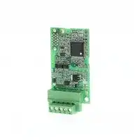
## **4 Option Components**
## **DeviceNet Option**
**==> picture [478 x 270] intentionally omitted <==**
**----- Start of picture text -----**<br>
G<br>F<br>A<br>SI-N3<br>B<br>Underside<br>C<br>E D<br>A – Connector (CN5) E – Ground terminal (FE) and installation hole <2><br>B – Installation hole F – Terminal block CN1<br>C – LED (MS) <1> G – Option model number<br>D – LED (NS) <1><br>**----- End of picture text -----**<br>
- <1> _**Refer to Option LED Display on page 10**_ for details on the LEDs.
- <2> Connect the provided ground wire during installation. Installation on GA700 and GA800 drives does not require the ground wire.
## **Figure 2 DeviceNet Option Components**
## **Terminal Block CN1**
The communication terminal is a pluggable terminal block that serves as the connection point of the DeviceNet network communication cable to the option.
**Table 2 Terminal Descriptions**
|**Terminal**|**Pin**|**Color**|**Signal**|**Description**|
|---|---|---|---|---|
||1|Black|V-<br>Net|work common|
||2|Blue|CAN_L<br>CA|N data Low|
||3|–|Shield<br>Cab|le shield|
||4|White|CAN_H<br>CA|N data High|
||5|Red|V+<br>Com|munications network power DC +24V|
**YASKAWA ELECTRIC** SIEP C730600 84D YASKAWA AC Drive Option SI-N3 Technical Manual
**9**
**4 Option Components**
## **Option LED Display**
The option has two bicolor, red/green LEDs: one for Module Status (MS) and one for Network Status (NS).
**==> picture [189 x 72] intentionally omitted <==**
**----- Start of picture text -----**<br>
NS MS<br>1000-Series Label GA700 and GA800 Label<br>**----- End of picture text -----**<br>
## **Figure 3 Option LED Labels**
The operational states of the LEDs after completion of the DeviceNet power-up diagnostic LED sequence are described in _**Table 4**_ . Wait at least 2 seconds for the power-up diagnostic process to complete before verifying the states of the LEDs.
**Table 3 Option LED States**
|**Name**|**Display**|**Display**|**Operating Status**|**Description**|
|---|---|---|---|---|
||**Color**|**Status**|||
|**MS**|–|OFF|Power supplyOFF|Power is not beingsupplied to the drive.|
||Green|ON|Option operating|The option is operatingnormally.|
||Green|Flashing|Option initializing|There is an incorrect baud rate settingor there is a MAC ID.|
||Red|ON|Fatal error occurred|A fatal(irrecoverable)error occurred in the option.|
||Red|Flashing|Non-fatal error occurred|A non-fatal(recoverable)error occurred.|
||Green/Red|Flashing|Device self-test|Device in self-test mode.|
|**NS**|–|OFF|Offline or Power supplyOFF|–|
||Green|ON|Online communications established|Device is on-line and has connections in the established state.|
||Green|Flashing|Online communications not<br>established|Device is on-line but has no connections in the established state.<br>Duplicate MAC ID test has been passed and is on-line but has no<br>open connections to other nodes.|
||Red|ON|Communications error|An error occurred disabling DeviceNet communications.<br>• MAC ID duplication<br>• Bus off detected|
||Red|Flashing|Communications time-out|A communications time-out occurred with the master.|
||Green/Red|Flashing|Communication faulted|Specific communication faulted device.<br>• The device has detected a network access error and is in the<br>communications faulted state.<br>• The device has then received and accepted an Identify<br>communication fault request-long protocol message.|
## **Power-Up Diagnostics**
An LED test is performed each time the drive is powered up. The initial boot sequence may take several seconds. The option is successfully initialized when the LEDs complete the diagnostic LED sequence. The LEDs then assume operational conditions shown in _**Table 3**_ .
**Table 4 Power-Up Diagnostic LED Sequence**
|**Sequence**|**Module Status(MS)**|**Network Status(NS)**|**Time(ms)**|
|---|---|---|---|
|1|Green|OFF|250|
|2|Red|OFF|250|
|3|Green|Green|250|
|4|Green|Red|250|
|5|Green|OFF|-|
**YASKAWA ELECTRIC** SIEP C730600 84D YASKAWA AC Drive Option SI-N3 Technical Manual
**10**
**5 Installation Procedure**
**5 Installation Procedure**
## **Section Safety**
## **DANGER**
## **Electrical Shock Hazard**
**Do not inspect, connect, or disconnect any wiring while the drive is energized.** Failure to comply will cause death or serious injury.
Before servicing, disconnect all power to the equipment and wait for at least the time specified on the warning label. The internal capacitor remains charged even after the drive is de-energized. The charge indicator LED will extinguish when the DC bus voltage is below 50 Vdc. When all indicators are OFF, measure for unsafe voltages to confirm the drive is safe.
## **W ARNING**
**Electrical Shock Hazard Do not operate equipment with covers removed.** Failure to comply could cause death or serious injury. The diagrams in this section may include options and drives without covers or safety shields to illustrate details. Reinstall covers and shields before operating the drive and run the drive according to the instructions described in this manual.
**Do not allow unqualified personnel to perform work on the drive or option.**
Failure to comply could cause death or serious injury.
Only authorized personnel familiar with installation, adjustment, and maintenance of AC drives and options may perform work.
**Do not remove covers or touch circuit boards while the drive is energized.** Failure to comply could cause death or serious injury.
**Do not use damaged wires, stress the wiring, or damage the wire insulation.** Failure to comply could cause death or serious injury. **Fire Hazard**
**Tighten all terminal screws to the specified tightening torque.** Loose or overtightened connections could cause erroneous operation and damage to the terminal block or start a fire and cause death or serious injury.
## **NOTICE**
**Damage to Equipment Observe proper electrostatic discharge (ESD) procedures when handling the option, drive, and circuit boards.** Failure to comply could cause ESD damage to circuitry. **Never connect or disconnect the motor from the drive while the drive is outputting voltage.** Improper equipment sequencing could damage the drive.
**Do not connect or operate any equipment with visible damage or missing parts.** Failure to comply could further damage the equipment.
## **Do not use unshielded wire for control wiring.**
Failure to comply may cause electrical interference resulting in poor system performance. Use shielded, twisted-pair wires and ground the shield to the ground terminal of the drive.
**YASKAWA ELECTRIC** SIEP C730600 84D YASKAWA AC Drive Option SI-N3 Technical Manual
**11**
**5 Installation Procedure**
## **NOTICE**
## **Properly connect all pins and connectors on the option and drive.**
Failure to comply could prevent proper operation and damage equipment.
**Confirm that all connections are correct after installing the option and connecting peripheral devices.** Failure to comply could damage the option.
## **Procedures for Installing and Wiring Options on a Drive**
Procedures for installing and wiring options differ depending on the drive model.
Refer to _**Table 5**_ to check the procedures for installing and wiring options on a drive.
**Table 5 Procedures for Installing and Wiring Options on a Drive**
|**Product Series**|**Procedures for Installing and Wiring**<br>**Options on a Drive**|**Page**|
|---|---|---|
|A1000|Procedure A|**_13_**|
|E1000|Procedure A|**_13_**|
|H1000|Procedure A|**_13_**|
|L1000A|Procedure A|**_13_**|
|U1000|Procedure A|**_13_**|
|Z1000U|Procedure A|**_13_**|
|Z1000|Procedure B|**_17_**|
|GA700|Procedure C|**_21_**|
|GA800|Procedure C|**_21_**|
**YASKAWA ELECTRIC** SIEP C730600 84D YASKAWA AC Drive Option SI-N3 Technical Manual
**12**
**5 Installation Procedure**
## **Procedure A**
This section shows the procedure to install and wire the option on a 1000-series drive.
## **Prepare the Drive for the Option**
Before you install the option on a YASKAWA L1000A-, U1000-, or Z1000U-Series Drive, make sure that the option software version is PRG: 1112 or later.
1. Correctly wire the drive as specified by the manual packaged with the drive.
2. Make sure that the drive functions correctly.
- Refer to _**Figure 4**_ for an exploded view of the drive with the option and related components for reference in the installation procedure.
- A
- N B C
- M D
- L K J E
- NS MS
- I H G F
- **A – Insertion point for CN5 J – Option terminal block (CN1) B – Option card K – Drive grounding terminal (FE) C – Front cover L – Connector CN5-A D – Keypad M – Connector CN5-B E – LED label (Not available for communication F – Terminal cover option installation.) G – Removable tabs for wire N – Connector CN5-C routing (Not available for communication**
- **H – Included screws option installation.) I – Ground wire**
**Figure 4 Drive Components with Option**
**YASKAWA ELECTRIC** SIEP C730600 84D YASKAWA AC Drive Option SI-N3 Technical Manual
**13**
**5 Installation Procedure**
## **Install the Option**
Remove the front covers of the drive before you install the option. Refer to the drive manual for information about how to remove the front covers. Different drive sizes have different cover removal procedures. You can only install this option into the **CN5-A** connector on the drive control board.
**DANGER!** _Electrical Shock Hazard. Do not inspect, connect, or disconnect any wiring while the drive is energized. Failure to comply will cause death or serious injury. Before servicing, disconnect all power to the equipment and wait for at least the time specified on the warning label. The internal capacitor remains charged even after the drive is de-energized. The charge indicator LED will extinguish when the DC bus voltage is below 50 Vdc. When all indicators are OFF, measure for unsafe voltages to confirm the drive is safe._
**1.** Shut off power to the drive, wait the appropriate amount of time for voltage to dissipate, then remove the keypad (D) and front covers (C, F).
Refer to the manual packaged with the drive for details on keypad and cover removal.
**NOTICE:** _Damage to Equipment. Observe proper electrostatic discharge (ESD) procedures when handling the option, drive, and circuit boards. Failure to comply could cause ESD damage to circuitry._
**==> picture [290 x 229] intentionally omitted <==**
**----- Start of picture text -----**<br>
C<br>D<br>F<br>**----- End of picture text -----**<br>
**Figure 5 Remove the Keypad, Front Cover, and Terminal Cover**
**2.** Affix the LED label (E) in the appropriate position on the drive front cover (C).
**==> picture [364 x 247] intentionally omitted <==**
**----- Start of picture text -----**<br>
C<br>E<br>NS MS<br>**----- End of picture text -----**<br>
**Figure 6 Affix the LED Label**
**YASKAWA ELECTRIC** SIEP C730600 84D YASKAWA AC Drive Option SI-N3 Technical Manual
**14**
**5 Installation Procedure**
**3.** Insert the option card (B) into the CN5-A (L) connector on the drive and fasten it into place using one of the included screws (H). Tighten the screw to 0.5 to 0.6 Nm (4.4 to 5.3 inlb).
**==> picture [323 x 288] intentionally omitted <==**
**----- Start of picture text -----**<br>
B<br>L<br>H<br>NS MS<br>**----- End of picture text -----**<br>
**Figure 7 Insert the Option Card**
**4.** Connect one end of the ground wire (I) to the ground terminal (K) using one of the remaining provided screws (H). Connect the other end of the ground wire (I) to the remaining ground terminal and installation hole on the option (B) using the last remaining provided screw (H). Tighten both screws to 0.5 to 0.6 Nm (4.4 to 5.3 inlb).
**==> picture [370 x 287] intentionally omitted <==**
**----- Start of picture text -----**<br>
K<br>I<br>H<br>**----- End of picture text -----**<br>
**Figure 8 Connect the Ground Wire**
**Note:** The drive has only two ground terminal screw holes (K). Two ground wires should share the same ground terminal when connecting three options.
**YASKAWA ELECTRIC** SIEP C730600 84D YASKAWA AC Drive Option SI-N3 Technical Manual
**15**
**5 Installation Procedure**
**5.** Firmly connect the DeviceNet communication cable to option terminal block (CN1). Install DeviceNet communications cables apart from main-circuit wiring and other electrical and power lines. Ensure the cable end is firmly connected (see _**Figure 22**_ ). Refer to _**Communication Cable Topology on page 24**_ for details.
**6.** Reattach the drive front covers (C, F) and the keypad (D).
**NOTICE:** _Do not pinch cables between the front covers and the drive. Failure to comply could cause erroneous operation._
**==> picture [373 x 283] intentionally omitted <==**
**----- Start of picture text -----**<br>
C<br>D<br>F<br>**----- End of picture text -----**<br>
**Figure 9 Replace the Front Covers and Keypad**
**7.** Set drive parameters in _**Table 7**_ for correct option performance.
**YASKAWA ELECTRIC** SIEP C730600 84D YASKAWA AC Drive Option SI-N3 Technical Manual
**16**
**5 Installation Procedure**
## **Procedure B**
This section shows the procedure to install and wire the option on a Z1000 drive.
## **Prepare the Drive for the Option**
Prior to installing the option, wire the drive, make necessary connections to the drive terminals, and verify that the drive functions normally without the option installed. Refer to the User Manual packaged with the drive for information on wiring and connecting the drive.
_**Figure 10**_ shows an exploded view of the drive with the option and related components for reference.
**==> picture [332 x 292] intentionally omitted <==**
**----- Start of picture text -----**<br>
A<br>B<br>C<br>D<br>E<br>J<br>I MSNS F<br>H G<br>A – Drive grounding terminal (FE) F – LED label<br>B – SI-N3 option G – Ground wire<br>C – Mounting screw H – Terminal block CN1<br>D – Drive front cover I – Insert connector CN5 here<br>E – HOA keypad J – Connector CN5<br>**----- End of picture text -----**<br>
**Figure 10 Drive Components with Option**
**YASKAWA ELECTRIC** SIEP C730600 84D YASKAWA AC Drive Option SI-N3 Technical Manual
**17**
**5 Installation Procedure**
## **Installing the Option**
Remove the front cover of the drive before you install the option.
Refer to the drive manual for information about how to remove the front covers. Different drive sizes have different cover removal procedures.
You can only install this option into the **CN5-A** connector on the drive control board.
**DANGER!** _Electrical Shock Hazard. Do not connect or disconnect wiring while the power is on. Failure to comply could result in death or serious injury. Before installing the option, disconnect all power to the drive and wait at least the amount of time specified on the drive front cover safety label. After all indicators are off, measure the DC bus voltage to confirm safe level, and check for unsafe voltages before servicing. The internal capacitor remains charged after the power supply is turned off._
**1.** Shut off power to the drive, wait the appropriate amount of time for voltage to dissipate, then remove the HOA keypad (E) and front cover (D).
**NOTICE:** _Damage to Equipment. Observe proper electrostatic discharge procedures (ESD) when handling the option, drive, and circuit boards. Failure to comply may result in ESD damage to circuitry._
**==> picture [196 x 202] intentionally omitted <==**
**----- Start of picture text -----**<br>
D<br>E<br>**----- End of picture text -----**<br>
**Figure 11 Remove the Front Cover and HOA Keypad**
**YASKAWA ELECTRIC** SIEP C730600 84D YASKAWA AC Drive Option SI-N3 Technical Manual
**18**
**5 Installation Procedure**
**2.** With the front cover and HOA keypad removed, apply the LED label (F) in the appropriate position on the drive front cover (D).
**Note:** Place the LED label vertically on Z1000 drives as shown in _**Figure 12**_ .
**==> picture [195 x 201] intentionally omitted <==**
**----- Start of picture text -----**<br>
D<br>F<br>MS<br>NS<br>**----- End of picture text -----**<br>
**Figure 12 Apply the LED Label**
**3.** Make sure the screws on the left and right sides of the option terminal block (H) are tightened with a tightening torque of 0.5 to 0.6 Nm (4.4 to 5.3 inlb), then insert the option (B) into the CN5 connector (J) located on the drive and fasten it using one of the included screws (C).
**==> picture [205 x 197] intentionally omitted <==**
**----- Start of picture text -----**<br>
B<br>C<br>J<br>H<br>**----- End of picture text -----**<br>
**Figure 13 Insert the Option**
**YASKAWA ELECTRIC** SIEP C730600 84D YASKAWA AC Drive Option SI-N3 Technical Manual
**19**
**5 Installation Procedure**
**4.** Connect the ground wire (G) to the ground terminal (A) using one of the remaining provided screws (C). Connect the other end of the ground wire (G) to the ground terminal and installation hole on the option using the last remaining provided screw (C) and tighten both screws to 0.5 to 0.6 Nm (4.4 to 5.3 inlb).
**==> picture [196 x 205] intentionally omitted <==**
**----- Start of picture text -----**<br>
A<br>C<br>G<br>**----- End of picture text -----**<br>
**Figure 14 Connect the Ground Wire**
**5.** Wire the communication cables.
**Note:** Separate communication cables from main circuit wiring and other electrical lines.
**6.** Firmly connect the Ethernet communication cable to the option modular connector (CN1). Install Ethernet communications cables apart from main-circuit wiring and other electrical and power lines. Ensure the cable end is firmly connected (see _**Figure 22**_ ). Refer to _**Communication Cable Topology on page 24**_ for details of installing.
**7.** Reattach the drive front cover (D) and the HOA Keypad (E).
**==> picture [196 x 202] intentionally omitted <==**
**----- Start of picture text -----**<br>
D<br>E<br>**----- End of picture text -----**<br>
**Figure 15 Replace the Front Cover and HOA Keypad**
- **Note:** Take proper precautions when wiring the option so that the front covers will easily fit back onto the drive. Make sure no cables are pinched between the front covers and the drive when replacing the covers.
**8.** Set drive parameters in _**Table 7**_ for correct option performance.
**YASKAWA ELECTRIC** SIEP C730600 84D YASKAWA AC Drive Option SI-N3 Technical Manual
**20**
**5 Installation Procedure**
## **Procedure C**
This section shows the procedure to install and wire the option on a GA700 or GA800 drive.
## **Prepare the Drive for the Option**
Before you install the option on a YASKAWA AC Drive GA700 or GA800, make sure that the option software version is PRG: 1115 or later.
1. Correctly wire the drive as specified by the manual packaged with the drive.
2. Make sure that the drive functions correctly.
- Refer to _**Figure 16**_ for an exploded view of the drive with the option and related components for reference in the installation procedure.
**==> picture [273 x 177] intentionally omitted <==**
**----- Start of picture text -----**<br>
A<br>B<br>C<br>E<br>D<br>K<br>F<br>J<br>I<br>H<br>G<br>**----- End of picture text -----**<br>
- **A – Insertion point for CN5 connector I – Connector CN5-A B – SI-N3 option J – Connector CN5-B C – Included screws (Not available for communication D – Drive front cover option installation.) E – LED label K – Connector CN5-C F – Keypad (Not available for communication G – Option terminal block (CN1) option installation.)**
- **G – Option terminal block (CN1)**
- **H – LED Status Ring board**
**Figure 16 Drive Components with Option**
## **Install the Option**
Remove the front cover of the drive before you install the option. Refer to the drive manual for information about how to remove the front cover. Different drive sizes have different cover removal procedures. You can only install this option into the **CN5-A** connector on the drive control board.
**DANGER!** _Electrical Shock Hazard. Do not inspect, connect, or disconnect any wiring while the drive is energized. Failure to comply will cause death or serious injury. Before servicing, disconnect all power to the equipment and wait for at least the time specified on the warning label. The internal capacitor remains charged even after the drive is de-energized. The charge indicator LED will extinguish when the DC bus voltage is below 50 Vdc. When all indicators are OFF, measure for unsafe voltages to confirm the drive is safe._
**1.** Affix the LED label (E) in the appropriate position on the drive front cover (D).
**==> picture [160 x 142] intentionally omitted <==**
**----- Start of picture text -----**<br>
E<br>D<br>A1000<br>**----- End of picture text -----**<br>
**Figure 17 Affix the LED Label**
**YASKAWA ELECTRIC** SIEP C730600 84D YASKAWA AC Drive Option SI-N3 Technical Manual
**21**
**5 Installation Procedure**
**2.** Shut off power to the drive, wait the appropriate amount of time for voltage to dissipate, then remove the front cover (D).
Refer to the manual packaged with the drive for details on cover removal.
**NOTICE:** _Damage to Equipment. Observe proper electrostatic discharge (ESD) procedures when handling the option, drive, and circuit boards. Failure to comply could cause ESD damage to circuitry._
**==> picture [257 x 206] intentionally omitted <==**
**----- Start of picture text -----**<br>
Move the keypad connector to the holder on the drive after<br>removing the keypad and before removing the front cover.<br>Insert the keypad connector tab into the holder when installing<br>the keypad connector to the holder.<br>Holder<br>Keypad connector tab<br>Keypad<br>connector<br>**----- End of picture text -----**<br>
**Figure 18 Remove the Front Cover and Keypad**
**3.** Carefully remove the LED Status Ring board (H) and place it on the right side of the drive using the temporary placement holes.
Refer to the manual packaged with the drive for details on removing the LED Status Ring board.
**NOTICE:** _Do not remove the LED Status Ring board cable connector. Failure to comply could cause erroneous operation and damage the drive._
**==> picture [266 x 121] intentionally omitted <==**
**----- Start of picture text -----**<br>
H<br>Temporary placement holes<br>A1000<br>Drive front view<br>**----- End of picture text -----**<br>
**Figure 19 Remove the LED Status Ring Board**
**YASKAWA ELECTRIC** SIEP C730600 84D YASKAWA AC Drive Option SI-N3 Technical Manual
**22**
**5 Installation Procedure**
**4.** Insert the option card (B) into the CN5-A connector (I) on the drive and fasten it into place using the included screws (C). Tighten both screws to 0.5 to 0.6 Nm (4.4 to 5.3 inlb).
**Note:** Installing the option card on GA700 and GA800 drives requires only two screws and does not require a ground wire. The option package ships with three screws and a ground wire for installation on other product series. Do not use the ground wire or the extra screw.
**==> picture [246 x 177] intentionally omitted <==**
**----- Start of picture text -----**<br>
A1000<br>B<br>C<br>I<br>**----- End of picture text -----**<br>
## **Figure 20 Insert the Option Card**
**5.** Firmly connect the DeviceNet communication cable to option terminal block(CN1). Install DeviceNet communications cables apart from main-circuit wiring and other electrical and power lines. Ensure the cable end is firmly connected (see _**Figure 22**_ ). Refer to _**Communication Cable Topology on page 24**_ for details.
- **Note:** Maximum transmission distance is 100 m (328 ft). Minimum wiring distance between stations is 0.2 m (7.9 in).
**6.** Reattach the LED Status Ring board (H).
Use the open space provided inside the LED Status Ring board to route option wiring.
**NOTICE:** _Do not pinch cables between the front cover or the LED Status Ring board and the drive. Failure to comply could cause erroneous operation._
**7.** Reattach the drive front cover (D) and the keypad (F).
**==> picture [241 x 229] intentionally omitted <==**
**----- Start of picture text -----**<br>
Install the keypad to the drive after replacing<br>the keypad connector and then the keypad<br>connector. At that time, insert the keypad<br>connector tab into the drive.<br>Tab<br>Keypad<br>connector<br>D<br>F<br>H<br>**----- End of picture text -----**<br>
**Figure 21 Replace the Front Cover and Keypad**
**8.** Set drive parameters in _**Table 7**_ for correct option performance.
**YASKAWA ELECTRIC** SIEP C730600 84D YASKAWA AC Drive Option SI-N3 Technical Manual
**23**
**5 Installation Procedure**
## **Option Connection Diagram**
**==> picture [418 x 200] intentionally omitted <==**
**----- Start of picture text -----**<br>
R U<br>Power S V M Motor<br>T W<br>Drive<br>CN5-A<br>DeviceNet Communication Cable<br>FE <1><br>(Red)<br>V+ SI-N3<br>DeviceNet Communication Master (Black)<br>V-<br>or (White)<br>CAN_H<br>drop line (Blue)<br>CAN_L<br>Shield<br>**----- End of picture text -----**<br>
**Figure 22 Option Connection Diagram**
- <1> Connect the provided ground wire for installations on 1000-series drives. The ground wire is not necessary for installation on GA700 or GA800 drives.
## **Communication Cable Topology**
Refer to the ODVA website (www.odva.org) for more information on network cabling.
Refer to _**Trunk Line and Drop Line Length on page 100**_ for details on selecting trunk line and drop line lengths. Route the option wiring accroding to the following procedures.
**1.** Prepare the communication cables as shown in _**Figure 23**_ .
**==> picture [249 x 64] intentionally omitted <==**
**----- Start of picture text -----**<br>
Insulation<br>Option terminal DeviceNet Communication Master<br>Shield<br>Shield Shield sheath<br>(Insulate with electrical tape<br>or heat-shrink tubing)<br>**----- End of picture text -----**<br>
## **Figure 23 Prepare Ends of Shielded Cable**
**2.** Connect the communication cables to the terminal block as shown in _**Figure 24**_ . When attaching the CN1 connector plug on the terminal block to the socket, make sure the screws on the left and right sides of the plug are tightened with a tightening torque of 0.5 to 0.6 (Nm) or 4.4 to 5.43 (inlb).
**3.** Take particular caution to ensure that each wire is properly connected and wire insulation is not accidentally pinched into electrical terminals. Trim any frayed wires.
**WARNING!** _Fire Hazard. Tighten all terminal screws to the specified tightening torque. Loose or overtightened connections could cause erroneous operation and damage to the terminal block or start a fire and cause death or serious injury._
**NOTICE:** _Heat shrink tubing or electrical tape may be required to ensure that cable shielding does not come into contact with other wiring. Insufficient insulation may cause a short circuit that can damage the option or the drive._
**YASKAWA ELECTRIC** SIEP C730600 84D YASKAWA AC Drive Option SI-N3 Technical Manual
**24**
**5 Installation Procedure**
**==> picture [406 x 184] intentionally omitted <==**
**----- Start of picture text -----**<br>
Preparing wire ends: Screwdriver blade size<br>Pull back the shielding and lightly<br>twist the end with fingers, keeping<br>the ends from fraying.<br>Blade depth of<br>0.4 mm or less Tightening torque:<br>0.5 to 0.6 N�m<br>about 5.5 mm (7/32”) or 4.4 to 5.3 in�lb<br>When not using Blade width of<br>crimped insulated 2.5 mm or less<br>sleeves<br>Loosen the screws and<br>insert the wire into the<br>Terminal block CN1<br>opening on the terminal block.<br>DeviceNet Communication Cable<br>(do not solder ends)<br>**----- End of picture text -----**<br>
**Figure 24 Connect Cable Wiring**
## **Termination Resistor Connection**
Refer to the ODVA website (www.odva.org) for more information on network cabling.
Only connect network termination resistors (121 Ω, ±1%, 1/4 W) to nodes of the two ends of trunk line. Refer to ODVA specifications for more details on DeviceNet termination.
## **Option MAC ID**
## **Parameter F6-50, MAC ID Setting 0 to 64**
The option MAC ID is set with drive parameter F6-50. MAC ID settings between 0 to 63 are considered valid MAC IDs; setting 64 indicates a network-settable MAC ID.
The option reads the MAC ID value from F6-50 upon power-up and upon a network reset.
## **Option Baud Rate**
The option supports standard baud rates of 125 kbps, 250 kbps, and 500 kbps.
**Table 6 Parameter F6-51 Baud Rate Setting**
|**Description**|**Value**|
|---|---|
|125 kbps|0|
|250 kbps|1|
|500 kbps|2|
|Programmable from Network|3|
|Auto Detect|4|
## **Auto Baud Rate Sensing (F6-51 = 4)**
Setting parameter F6-51 to 4 enables automatic baud rate detection and allows the option to automatically determine the baud rate of the DeviceNet network.
**Note:** Auto baud rate sensing is valid only when there is more than one node physically on the DeviceNet network segment. If the auto baud rate sensing fails to detect the baud rate, the drive keypad will display “bUS” and the option LEDs will be OFF (NS) and solid green (MS).
## **EDS Files**
To facilitate network implementation, obtain an EDS file from one of the following websites depending on your region: U.S.: http://www.yaskawa.com Europe: http://www.yaskawa.eu.com Japan: http://www.e-mechatronics.com Other areas: Check the back cover of these manuals. For questions, contact Yaskawa or a Yaskawa representative.
**YASKAWA ELECTRIC** SIEP C730600 84D YASKAWA AC Drive Option SI-N3 Technical Manual
**25**
**6 Related Parameters**
## **6 Related Parameters**
The parameters in _**Table 7**_ set the drive for operation with the option. Confirm proper setting of all parameters in _**Table 7**_ before starting network communications. Refer to the manual packaged with the drive for details on setting parameters.
**Note:** Hex.: MEMOBUS addresses that you can use to change parameters over network communication are represented in hexadecimal numbers.
**Table 7 Related Parameters**
|**No.**<br> **(Hex.)**|**Name**|**Description**|**Values**|
|---|---|---|---|
|b1-01<br>(0180)<br>**_<1>_**|Reference 1 Source|Selects the input method for frequency reference.<br>0: Keypad<br>1: Analog Input<br>2: Memobus/Modbus Communications<br>3: Option PCB<br>4: Pulse Train Input|Default: 1<br>Range: 0 to 4|
|b1-02<br>(0181)<br>**_<1>_**|Run Command 1 Source|Selects the input method for the Run command.<br>0: Keypad<br>1: Digital Input<br>2: Memobus/Modbus Communications<br>3: Option PCB|Default: 1<br>Range: 0 to 3|
|F6-01<br>(03A2)|Communication Error<br>Selection|Selects drive response when a bUS error is detected during communications with the<br>option.<br>0: Ramp to Stop<br>1: Coast to Stop<br>2: Fast Stop (Use C1-09)<br>3: Alarm Only**_<2>_**<br>4: Alarm - Run at d1-04**_<2> <3>_**<br>5: Alarm - Rampto Stop **_<3>_**|Default: 1<br>Range: 0 to 5**_<4>_**|
|F6-02<br>(03A3)|Comm External Fault (EF0)<br>Detect|Selects the condition for external fault detection (EF0).<br>0: Always detected<br>1: Detection duringrun only|Default: 0<br>Range: 0, 1|
|F6-03<br>(03A4)|Comm External Fault (EF0)<br>Select|Selects drive response for external fault input (EF0) detection during option<br>communications.<br>0: Ramp to Stop<br>1: Coast to Stop<br>2: Fast Stop (Use C1-09)<br>3: Alarm Only**_<2>_**|Default: 1<br>Range: 0 to 3|
|F6-06<br>(03A7)<br>**_<5>_**|Torque Reference/Limit by<br>Comm|Selects whether to enable or disable the torque reference and torque limit received<br>from the communication option card.<br>0: Disabled<br>1: Enabled**_<6>_**|Default: 0<br>Range: 0, 1|
|F6-07<br>(03A8)|MultiStep Ref Priority<br>Select|0: MultiStep References Disabled<br>1: MultiStep References Enabled|Default: 0<br>Range: 0, 1|
|F6-08<br>(036A)|Comm Parameter Reset<br>@Initialize|Selects whether communication-related parameters F6-and F7-are set back<br>to original default values when the drive is initialized using parameter A1-03.<br>0: No Reset - Parameters retained<br>1: Reset - Back to factory default<br>Note: The setting value is not changed even when F6-08 is set to 1 and the drive is<br>initialized usingA1-03.|Default: 0<br>Range: 0, 1|
|F6-15<br>(0B5B)<br>**_<7>_**|Comm. Option Parameters<br>Reload|Selects whether F6-/F7-communication-related parameters changed are<br>enabled.<br>0: Reload at Next Power Cycle<br>1: Reload Now<br>2: Cancel Reload Request<br>Note: F6-15 is reset to 0 after setting1 or 2.|Default: 0<br>Range: 0 to 2|
|F6-50<br>(03C1)<br>**_<8>_** **_<9>_**|DN MAC Address|Selects the drive MAC address<br>**Note:**Used in the DeviceNet Object|Default: 0**_<10>_**<br>Min: 0<br>Max: 64|
**YASKAWA ELECTRIC** SIEP C730600 84D YASKAWA AC Drive Option SI-N3 Technical Manual
**26**
**6 Related Parameters**
|**No.**<br> **(Hex.)**|**Name**|**Description**|**Values**|
|---|---|---|---|
|F6-51<br>(03C2)<br>**_<9>_**|DN Baud Rate|DeviceNet communication speed<br>0: 125 kbps<br>1: 250 kbps<br>2: 500 kbps<br>3: Adjustable from network<br>4: Detect automatically<br>**Note:**Used in the DeviceNet Object|Default: 0**_<10>_**<br>Range: 0 to 4|
|F6-52<br>(03C3)<br>**_<11>_**|DeviceNet PCA Setting|I/O Polled Consuming Assembly data instance<br>**Note:**Used in the Connection Object|Default: 21<br>Min: 0<br>Max: 255|
|F6-53<br>(03C4)<br>**_<11>_**|DeviceNet PPA Setting|I/O Polled Producing Assembly data instance<br>**Note:**Used in the Connection Object|Default: 71<br>Min: 0<br>Max: 255|
|F6-54<br>(03C5)<br>**_<9>_**|DN Idle Flt Det|Determines what the drive should do when communication goes into idle mode.<br>0: Stop, drive will stop<br>1: Ignore, drive will continue what it was doing<br>2: Vendor Specific, drive will use to F6-01 to determine whether it should stop or<br>continue<br>3: Run Fwd, the drive will run in the forward direction<br>4: Run Rev, the drive will run in the reverse direction|Default: 0<br>Range: 0 to 4|
|F6-55<br>(03C6)|DN BAUD RATE MEM|Displays the baud rate currently being used for network communications. F6-55 is<br>used only as a monitor.<br>0: 125 kbps<br>1: 250 kbps<br>2: 500 kbps<br>**Note:**Used in the DeviceNet Object|Default: 0<br>Range: 0 to 2|
|F6-56<br>(03D7)|DeviceNet Speed Scaling|Sets the scaling factor for the Speed Monitor in the DeviceNet Object Class 2A hex<br>**Note:**Used in the AC/DC Drive Object|Default: 0<br>Min: -15<br>Max: 15|
|F6-57<br>(03D8)|DeviceNet Current Scaling|Sets the scaling factor for the Output Current Monitor in the DeviceNet Object Class<br>2A hex<br>**Note:**Used in the AC/DC Drive Object|Default: 0<br>Min: -15<br>Max: 15|
|F6-58<br>(03D9)|DeviceNet Torque Scaling|Sets the scaling factor for the Torque Monitor in the DeviceNet Object Class 2A hex<br>**Note:**Used in the AC/DC Drive Object|Default: 0<br>Min: -15<br>Max: 15|
|F6-59<br>(03DA)|DeviceNet Power Scaling|Sets the scaling factor for the Power Monitor in the DeviceNet Object Class 2A hex<br>**Note:**Used in the AC/DC Drive Object|Default: 0<br>Min: -15<br>Max: 15|
|F6-60<br>(03DB)|DeviceNet Voltage Scaling|Sets the scaling factor for the Voltage Monitor in the DeviceNet Object Class 2A<br>**Note:**Used in the AC/DC Drive Object|Default: 0<br>Min: -15<br>Max: 15|
|F6-61<br>(03DC)|DeviceNet Time Scaling|Sets the scaling factor for the Time Monitor in the DeviceNet Object Class 2A hex<br>**Note:**Used in the AC/DC Drive Object|Default: 0<br>Min: -15<br>Max: 15|
|F6-62<br>(03DD)|DeviceNet Heartbeat<br>Interval|Sets the heartbeat interval. A setting of 0 disables the heartbeat function.<br>**Note:**Used in the Identity Object|Default: 0<br>Min: 0<br>Max: 10|
|F6-63<br>(03DE)|DeviceNet Network MAC<br>ID|Displays the MAC ID assigned to the drive. F6-63 is used only as a monitor.<br>**Note:**Used in the DeviceNet Object|Default: 0**_<10>_**<br>Min: 0<br>Max: 63|
|F6-64<br>(03DF)<br>**_<12>_**|Dynamic Out Assembly<br>109 Param1 (DOA109 1)|The data in configurable output 1 is written to the MEMOBUS/Modbus address<br>defined by this parameter.|Default: 0x0000<br>Min: 0x0000<br>Max: 0xFFFF|
|F6-65<br>(03E0)<br>**_<12>_**|Dynamic Out Assembly<br>109 Param2 (DOA109 2)|The data in configurable output 2 is written to the MEMOBUS/Modbus address<br>defined by this parameter.|Default: 0x0000<br>Min: 0x0000<br>Max: 0xFFFF|
|F6-66<br>(03E1)<br>**_<12>_**|Dynamic Out Assembly<br>109 Param3 (DOA109 3)|The data in configurable output 3 is written to the MEMOBUS/Modbus address<br>defined by this parameter.|Default: 0x0000<br>Min: 0x0000<br>Max: 0xFFFF|
|F6-67<br>(03E2)<br>**_<12>_**|Dynamic Out Assembly<br>109 Param4 (DOA109 4)|The data in configurable output 4 is written to the MEMOBUS/Modbus address<br>defined by this parameter.|Default: 0x0000<br>Min: 0x0000<br>Max: 0xFFFF|
**YASKAWA ELECTRIC** SIEP C730600 84D YASKAWA AC Drive Option SI-N3 Technical Manual
**27**
**6 Related Parameters**
|**No.**<br> **(Hex.)**|**Name**|**Description**|**Values**|
|---|---|---|---|
|F6-68<br>(03E3)<br>**_<12>_**|Dynamic In Assembly 159<br>Param 1 (DIA159 1)|The data in configurable input 1 is read from the MEMOBUS/Modbus address defined<br>by this parameter.|Default: 0x0000<br>Min: 0x0000<br>Max: 0xFFFF|
|F6-69<br>(03E4)<br>**_<12>_**|Dynamic In Assembly 159<br>Param 2 (DIA159 2)|The data in configurable input 2 is read from the MEMOBUS/Modbus address defined<br>by this parameter.|Default: 0x0000<br>Min: 0x0000<br>Max: 0xFFFF|
|F6-70<br>(03C7)<br>**_<12>_**|Dynamic In Assembly 159<br>Param 3 (DIA159 3)|The data in configurable input 3 is read from the MEMOBUS/Modbus address defined<br>by this parameter.|Default: 0x0000<br>Min: 0x0000<br>Max: 0xFFFF|
|F6-71<br>(03C8)<br>**_<12>_**|Dynamic In Assembly 159<br>Param 4 (DIA159 4)|The data in configurable input 4 is read from the MEMOBUS/Modbus address defined<br>by this parameter.|Default: 0x0000<br>Min: 0x0000<br>Max: 0xFFFF|
|U6-97<br>(07F7)|OPT SPARE 4|Displays option software version|–|
|U6-98<br>(07F8)|First Fault|Displays previous faulted status.<br>0: No fault<br>1: Option failure<br>2: PLC in idle state<br>3: Force fault<br>1000: Network power loss<br>1001: Connection timeout<br>1002: Duplicate MAC ID<br>1003: Bus-off<br>**Note:**Used in DeviceNet Option Faults|–|
|U6-99<br>(07F9)|Current Fault|Displays the most recent fault status.<br>0:No fault<br>1: Option failure<br>2: PLC in idle state<br>3: Force fault<br>1000: Network power loss<br>1001: Connection timeout<br>1002: Duplicate MAC ID<br>1003: Bus-off<br>**Note:**Used in DeviceNet Option Faults|–|
<1> To start and stop the drive with the DeviceNet master device using serial communications, set b1-02 to 3 or set the Net Control bit in the assemblies or Control Supervisor Object. To control the frequency reference of the drive via the master device, set b1-01 to 3 or set the Net Reference bit in the assemblies or AC/DC object.
<2> Setting this parameter to 3 or 4 will cause the drive to continue operation after detecting a fault. Take proper measures such as installing an emergency stop switch when using settings 3 or 4.
<3> Refer to the drive manual to know if settings 4 and 5 are available. Settings 4 and 5 are available in A1000 software versions PRG: 1021 and later.
<4> The setting range for 1000-Series drives is different for different software versions. Refer to the instruction manual of a specific drive for more information.
<5> Control method availability of this parameter depends on product series.
1000-Series Drives: Parameter is available in CLV, AOLV/PM, and CLV/PM.
In AOLV/PM, this value is read as the Torque Limit.
GA700, GA800 Drives: Parameter is available in OLV, CLV, AOLV, AOLV/PM, CLV/PM, and EZOLV.
In OLV and EZOLV, this value is read as the Torque Limit.
<6> The setting specifies that network communications provide the torque reference or torque limit. The motor may not rotate if the PLC does not supply a torque reference or torque limit.
<7> Supported on PRG: 1115. Not available on 1000-series drives.
- <8> All MAC addresses must be unique.
<9> Cycle power for setting changes to take effect.
<10> The default setting depends on region code. Refer to _**Table 8**_ on page _**28**_ for more information.
<11> Setting unavailable values will initialize Polled Consuming Assembly (PCA) and Polled Producing Assembly (PPA).
<12> Available in the option software versions PRG: 1111 and later.
## **Table 8 Regional Default Setting**
|**No.**|**Name**|**Default by Region Code**<br>**Example: CIMR-V****or GA70**|**Default by Region Code**<br>**Example: CIMR-V****or GA70**|
|---|---|---|---|
|||**Code: A, B, C, D, K, T**<br>**(Japan, China, Europe,**<br>**India, Korea, Asia)**|**Code: U**<br>**(The Americas)**|
|F6-50|DeviceNet MAC Address|0|64|
|F6-51|DeviceNet Baud Rate|0|4|
|F6-63|DeviceNet Network MAC ID|0|63|
**YASKAWA ELECTRIC** SIEP C730600 84D YASKAWA AC Drive Option SI-N3 Technical Manual
**28**
**7 Configuring DeviceNet Messaging**
## **7 Configuring DeviceNet Messaging**
This section provides information on the methods used to control the drive on DeviceNet.
## **Drive Configuration on DeviceNet**
## **Polled Configuration**
Configure the drive DeviceNet polled connection before receiving commands from a master device. The two parameters that must be configured are:
- F6-52: Polled Consuming Assembly (PCA) **Note:** Output assembly consumed by the drive.
- F6-53: Polled Producing Assembly (PPA)
- **Note:** Input assembly produced by the drive.
The default connection paths for the option are set for Extended Speed Control.
The PCA and PPA parameters can be accessed by two methods:
- A software configuration tool (not supplied), and Yaskawa Electronic Data Sheet (EDS) **Note:** The PCA and PPA parameters can be accessed from the “DN: Polled Config” parameter group.
- A software configuration tool (not supplied), via a DeviceNet message path, such as Extended Speed Control **Note:** Use DeviceNet Connection Object to change the PCA or PPA if required by the application (Class 5, Instance 1, Attributes 14 and 16)
One of each PCA and PPA assembly from the following table must be selected to configure the drive for polled operation.
Refer to PCA on page _**31**_ and PPA on page _**54**_ for more information about each assembly.
**Table 9 Supported Polled Assemblies (PCA and PPA)**
|**Assembly Number**<br>**(decimal)**|**Description**|**Type**|**Bytes**|
|---|---|---|---|
|20|**_Basic Speed Control Output - 20(0x14)_**|PCA|4|
|21|**_Extended Speed Control Output - 21 (0x15)_** (Default Setting)|PCA|4|
|22|**_Speed and Torque Control Output - 22 (0x16)_**|PCA|6|
|23|**_Extended Speed and Torque Control Output - 23(0x17)_**|PCA|6|
|70|**_Basic Speed Control Input - 70 (0x46)_**|PPA|4|
|71|**_Extended Speed Control Input - 71 (0x47)_** (Default Setting)|PPA|4|
|72|**_Speed and Torque Control Input - 72(0x48)_**|PPA|6|
|73|**_Extended Speed and Torque Control Input - 73 (0x49)_**|PPA|6|
|100|**_MEMOBUS/Modbus Message Command (Vendor Specific Yaskawa Electric (YE) Assy) - 100 (0x64)_**|PCA|5|
|101|**_Standard Control(Vendor Specific Yaskawa Electric(YE) Assy) - 101(0x65)_**|PCA|8|
|102|**_Accel/Decel Time (Vendor Specific Yaskawa Electric (YE) Assy) - 102 (0x66)_**|PCA|8|
|103<br>**_<1>_**|**_3-Wire Control1 (Vendor Specific Yaskawa Electric (YE) Assy) - 103 (0x67)_**|PCA|4|
|104<br>**_<1>_**|**_3-Wire Control Status1 (Vendor Specific Yaskawa Electric (YE) Assy) - 104 (0x68)_**|PPA|4|
|105|**_Enhanced Speed Control, Dynamic (Vendor Specific Yaskawa Electric (YE) Assy) - 105 (0x69)_**|PCA|8|
|106|**_Enhanced Control(Vendor Specific Yaskawa Electric(YE) Assy) - 106(0x6A)_**|PCA|8|
|107|**_Standard DI/DO Control (Vendor Specific Yaskawa Electric (YE) Assy) - 107 (0x6B)_**|PCA|8|
|108|**_Enhanced Torque Control, Dynamic (Vendor Specific Yaskawa Electric (YE) Assy) - 108 (0x6C)_**|PCA|8|
|109<br>**_<2>_**|**_Dynamic Output Assembly (Vendor Specific Yaskawa Electric (YE) Assy) - 109 (0x6D)_**|PCA|8|
|110<br>**_<3>_**|**_3-Wire Control2 (Vendor Specific Yaskawa Electric (YE) Assy) - 110 (0x6E)_**|PCA|4|
|120|**_Speed Command 1(Vendor Specific Yaskawa Electric(YE) Assy) - 120(0x78)_**|PCA|4|
|121|**_Torque Command 1 (Vendor Specific Yaskawa Electric (YE) Assy) - 121 (0x79)_**|PCA|4|
|122|**_Speed Command 2 (Vendor Specific Yaskawa Electric (YE) Assy) - 122 (0x7A)_**|PCA|6|
**YASKAWA ELECTRIC** SIEP C730600 84D YASKAWA AC Drive Option SI-N3 Technical Manual
**29**
**7 Configuring DeviceNet Messaging**
|**Assembly Number**<br>**(decimal)**|**Description**|**Type**|**Bytes**|
|---|---|---|---|
|123|**_Torque Command 2(Vendor Specific Yaskawa Electric(YE) Assy) - 123(0x7B)_**|PCA|6|
|124|**_Speed Dynamic Assy (Vendor Specific Yaskawa Electric (YE) Assy) - 124 (0x7C)_**|PCA|8|
|125|**_Torque Dynamic Assy (Vendor Specific Yaskawa Electric (YE) Assy) - 125 (0x7D)_**|PCA|8|
|126|**_Speed/Torque Assy (Vendor Specific Yaskawa Electric(YE) Assy) - 126(0x7E)_**|PCA|8|
|130|**_Speed Status (Vendor Specific Yaskawa Electric (YE) Assy) - 130 (0x82)_**|PPA|4|
|131|**_Current Status (Vendor Specific Yaskawa Electric (YE) Assy) - 131 (0x83)_**|PPA|4|
|132|**_Current & Speed Status(Vendor Specific Yaskawa Electric(YE) Assy) - 132(0x84)_**|PPA|6|
|134|**_Speed Status Dynamic Assy (Vendor Specific Yaskawa Electric (YE) Assy) - 134 (0x86)_**|PPA|8|
|135|**_Current Status Dynamic Assy (Vendor Specific Yaskawa Electric (YE) Assy) - 135 (0x87)_**|PPA|8|
|136|**_Torque and Speed Status(Vendor Specific Yaskawa Electric(YE) Assy) - 136(0x88)_**|PPA|8|
|150|**_MEMOBUS/Modbus Message Reply (Vendor Specific Yaskawa Electric (YE) Assy) - 150 (0x96)_**|PPA|5|
|151|**_Standard Status 1 (Vendor Specific Yaskawa Electric (YE) Assy) - 151 (0x97)_**|PPA|8|
|152|**_Standard Status 2(Vendor Specific Yaskawa Electric(YE) Assy) -152(0x98)_**|PPA|8|
|155|**_Enhanced Speed Status, Dynamic (Vendor Specific Yaskawa Electric (YE) Assy) - 155 (0x9B)_**|PPA|8|
|156|**_Enhanced Control Status (Vendor Specific Yaskawa Electric (YE) Assy) -156 (0x9C)_**|PPA|8|
|157|**_Standard DI/DO Status (Vendor Specific Yaskawa Electric (YE) Assy) - 157 (0x9D)_**|PPA|8|
|158|**_Enhanced Torque Status, Dynamic(Vendor Specific Yaskawa Electric(YE) Assy) - 158(0x9E)_**|PPA|8|
|159<br>**_<2>_**|**_Dynamic Input Assembly (Vendor Specific Yaskawa Electric (YE) Assy) - 159 (0x9F)_**|PPA|8|
|160<br>**_<3>_**|**_3-Wire Control Status2 (Vendor Specific Yaskawa Electric (YE) Assy) - 160 (0xA0)_**|PPA|4|
|199<br>**_<1>_**|**_Change of State Response (Vendor Specific Yaskawa Electric (YE) Assy) - 199 (0xC7)_**|PPA|8|
<1> Available in option software versions PRG: 1107 and later.
<2> Available in option software versions PRG: 1111 and later.
<3> Available in option software versions PRG: 1114 and later.
## **Additional Support for Setting Connection Path Types**
The option also supports symbolic encoding to support application tools and development tools that do not handle explicit message fragmentation. Symbolic encoding requires only a 3-byte long message where logical encoding requires 11 bytes.
The option has a third method of setting polled consumed and produced connection paths. Class 5, Instance 2, Attributes (100, 101) allow setting connection path with a single byte. For instance, to set the consumed connection path to 100, write 100 (0x64) to Attribute 101. See appendix C of “The CIP Networks Library, Volume 1" for more information on CIP segments
**YASKAWA ELECTRIC** SIEP C730600 84D YASKAWA AC Drive Option SI-N3 Technical Manual
**30**
**8 Output Assemblies (Drive Consumes)**
## **8 Output Assemblies (Drive Consumes)**
The convention in this manual is from the PLC perspective. As such, an assembly is called an “Output Assembly” when outputted from the PLC and received by this node. An “Input Assembly” is outputted from this node and read by the PLC. This section details “Output Assemblies” that are “Consumed” by the drive.
## **Basic Speed Control Output - 20 (0x14)**
|**Output Instance**|**Byte**|**Bit 7**|**Bit 6**|**Bit 5**|**Bit 4**|**Bit 3**|**Bit 2**|**Bit 1**|**Bit 0**|
|---|---|---|---|---|---|---|---|---|---|
|20|0|–|–|–|–|–|Fault<br>Reset|–|Run<br>Fwd|
||1|-||||||||
||2|Speed Reference(Low Byte)||||||||
||3|Speed Reference(High Byte)||||||||
|||||||||||
|**Name**||**Description**||||||||
|Run Fwd||Forward Run Command<br>0: Stop<br>1: Forward Run||||||||
|Fault Reset||Fault Reset<br>0: No Fault Reset<br>1: Fault Reset||||||||
|Speed Reference||Speed Command<br>Sets drive speed reference<br>Speed reference data:<br>Frequency reference / 2SS(SS: Speed scale)<br>Setting range: 0 to 0xFFFF<br>For example, when setting a reference of 1024 with a speed scale of 2<br>Speed reference data = 1024 / 22= 256 = 0x0100<br>Unit depends on o1-03.||||||||
## **Extended Speed Control Output - 21 (0x15)**
|**Output Instance**|**Byte**|**Bit 7**|**Bit 6**|**Bit 5**|**Bit 4**|**Bit 3**|**Bit 2**|**Bit 1**|**Bit 0**|
|---|---|---|---|---|---|---|---|---|---|
|21|0|–|Net<br>Ref|Net<br>Ctrl|–|–|Fault<br>Reset|Run<br>Rev|Run<br>Fwd|
||1|–||||||||
||2|Speed Reference(Low Byte)||||||||
||3|Speed Reference(High Byte)||||||||
|||||||||||
|**Name**||**Description**||||||||
|Run Fwd||Forward Run Command<br>0: Stop<br>1: Forward Run||||||||
|Run Rev||Reverse Run Command<br>0: Stop<br>1: Reverse Run||||||||
|Fault Reset||Fault Reset<br>0: No Fault Reset<br>1: Fault Reset||||||||
|NetCtrl||Run command from Network<br>0: Depends on b1-02<br>1: Enables the run command from network||||||||
|NetRef||Speed reference from Network<br>0: Depends on b1-01<br>1: Enables the speed reference from network||||||||
**YASKAWA ELECTRIC** SIEP C730600 84D YASKAWA AC Drive Option SI-N3 Technical Manual
**31**
**8 Output Assemblies (Drive Consumes)**
|**Name**|**Description**|
|---|---|
|Speed Reference|Speed Command<br>Sets drive speed reference<br>Speed reference data:<br>Frequency reference / 2SS(SS: Speed scale)<br>Setting range: 0 to 0xFFFF<br>For example, when setting a reference of 1024 with a speed scale of 2<br>Speed reference data = 1024 / 22= 256 = 0x0100<br>Unit depends on o1-03.|
## **Speed and Torque Control Output - 22 (0x16)**
|**Output Instance**|**Byte**|**Bit 7**|**Bit 6**|**Bit 5**|**Bit 4**|**Bit 3**|**Bit 2**|**Bit 1**|**Bit 0**|
|---|---|---|---|---|---|---|---|---|---|
|22|0|–|–|–|–|–|Fault<br>Reset|–|Run<br>Fwd|
||1|–||||||||
||2|Speed Reference(Low Byte)||||||||
||3|Speed Reference(High Byte)||||||||
||4|Torque Reference/Torque Limit(Low Byte)||||||||
||5|Torque Reference/Torque Limit(High Byte)||||||||
|||||||||||
|**Name**||**Description**||||||||
|Run Fwd||Forward Run Command<br>0: Stop<br>1: Forward Run||||||||
|Fault Reset||Fault Reset<br>0: No Fault Reset<br>1: Fault Reset||||||||
|Speed Reference||Speed Command<br>Sets drive speed reference<br>Speed reference data:<br>Frequency reference / 2SS(SS: Speed scale)<br>Setting range: 0 to 0xFFFF<br>For example, when setting a reference of 1024 with a speed scale of 2<br>Speed reference data = 1024 / 22= 256 = 0x0100<br>Unit depends on o1-03.||||||||
|Torque Reference/Torque Limit||Torque Reference/Torque Limit<br>Sets the torque reference and torque limit in units of 0.1%.<br>Sets the torque reference when using torque control (d5-01 = 1).<br>Sets the torque limit when using speed control (d5-01 = 0).<br>The torque reference and torque limit are disabled when F6-06 = 0.||||||||
## **Extended Speed and Torque Control Output - 23 (0x17)**
|**Output Instance**|**Byte**|**Bit 7**|**Bit 6**|**Bit 5**|**Bit 4**|**Bit 3**|**Bit 2**|**Bit 1**|**Bit 0**|
|---|---|---|---|---|---|---|---|---|---|
|23|0|–|Net<br>Ref|Net<br>Ctrl|–|–|Fault<br>Reset|Run<br>Rev|Run<br>Fwd|
||1|–||||||||
||2|Speed Reference(Low Byte)||||||||
||3|Speed Reference(High Byte)||||||||
||4|Torque Reference/Torque Limit(Low Byte)||||||||
||5|Torque Reference/Torque Limit(High Byte)||||||||
|||||||||||
|**Name**||**Description**||||||||
|Run Fwd||Forward Run Command<br>0: Stop<br>1: Forward Run||||||||
|Run Rev||Reverse Run Command<br>0: Stop<br>1: Reverse Run||||||||
**YASKAWA ELECTRIC** SIEP C730600 84D YASKAWA AC Drive Option SI-N3 Technical Manual
**32**
**8 Output Assemblies (Drive Consumes)**
|**Name**|**Description**|
|---|---|
|Fault Reset|Fault Reset<br>0: No Fault Reset<br>1: Fault Reset|
|NetCtrl|Run command from Network<br>0: Depends on b1-02<br>1: Enables the run command from network|
|NetRef|Speed reference from Network<br>0: Depends on b1-01<br>1: Enables the speed reference from network|
|Speed Reference|Speed Command<br>Sets drive speed reference<br>Speed reference data:<br>Frequency reference × 2SS(SS: Speed scale)<br>Setting range: 0 to 0xFFFF<br>For example, when setting a reference of 1024 with a speed scale of 2<br>Speed reference data = 1024 × 22= 4096 = 0x1000<br>Unit depends on o1-03.|
|Torque Reference/Torque Limit|Torque Reference/Torque Limit<br>Sets the torque reference and torque limit in units of 0.1%.<br>Sets the torque reference when using torque control (d5-01 = 1).<br>Sets the torque limit when using speed control (d5-01 = 0).<br>The torque reference and torque limit are disabled when F6-06 = 0.|
## **MEMOBUS/Modbus Message Command**
## **(Vendor Specific Yaskawa Electric (YE) Assy) - 100 (0x64)**
|**Output Instance**|**Byte**|**Bit 7**|**Bit 6**|**Bit 5**|**Bit 4**|**Bit 3**|**Bit 2**|**Bit 1**|**Bit 0**|
|---|---|---|---|---|---|---|---|---|---|
|100|0|Function Code||||||||
||1|Register Number(High Byte)||||||||
||2|Register Number(Low Byte)||||||||
||3|Register Data(High Byte)||||||||
||4|Register Data(Low Byte)||||||||
**Note:** This is a paired assembly (100/150).
|**Name**|**Description**|
|---|---|
|Function Code|MEMOBUS/Modbus Function Code<br>**_Refer to Function Code Decode Table onpage 33_**.|
|Register Number|MEMOBUS/Modbus Register Number|
|Register Data|MEMOBUS/Modbus Register Data|
## **Table 10 Function Code Decode Table**
|**Function Code**|**MEMOBUS/Modbus Function**|
|---|---|
|0x00|No Operation|
|0x03|Read Register|
|0x10|Write Register|
**Note:** Refer to the MEMOBUS/Modbus Data Table in the drive Technical Manual for a list of monitor data using the MEMOBUS/ Modbus message area.
**YASKAWA ELECTRIC** SIEP C730600 84D YASKAWA AC Drive Option SI-N3 Technical Manual
**33**
**8 Output Assemblies (Drive Consumes)**
## **Standard Control (Vendor Specific Yaskawa Electric (YE) Assy) - 101 (0x65)**
|**Output**<br>**Instance**|**Byte**|**Bit 7**|**Bit 6**|**Bit 5**|**Bit 4**|**Bit 3**|**Bit 2**|**Bit 1**|**Bit 0**|
|---|---|---|---|---|---|---|---|---|---|
|101|0|Multi-Function<br>Input 8|Multi-Function<br>Input 7|Multi-Function<br>Input 6|Multi-Function<br>Input 5|Multi-Function<br>Input 4|Multi-Function<br>Input 3|Run<br>Rev|Run<br>Fwd|
||1|YASKAWA<br>AC Drive<br>1000-Series<br>Multi-Function<br>Photocoupler 2<br>YASKAWA<br>AC Drive<br>GA700, GA800<br>Multi-Function<br>Digital Output 3|YASKAWA<br>AC Drive<br>1000-Series<br>Multi-Function<br>Photocoupler 1<br>YASKAWA<br>AC Drive<br>GA700, GA800<br>Multi-Function<br>Digital Output 2|YASKAWA<br>AC Drive<br>1000-Series<br>Multi-Function<br>Digital Output<br>YASKAWA<br>AC Drive<br>GA700, GA800<br>Multi-Function<br>Digital Output 1|–|–|–|Fault<br>Reset|External<br>Fault|
||2|Speed Reference(Low Byte)||||||||
||3|Speed Reference(High Byte)||||||||
||4|Torque Reference/Torque Limit(Low Byte)||||||||
||5|Torque Reference/Torque Limit(High Byte)||||||||
||6|Torque Compensation(Low Byte)||||||||
||7|Torque Compensation(High Byte)||||||||
|**Name**|**Description**|
|---|---|
|Run Fwd|Forward Run Command<br>0: Stop<br>1: Forward Run|
|Run Rev|Reverse Run Command<br>0: Stop<br>1: Reverse Run|
|Multi-Function Input 3|Terminal S3 Function Input<br>0: Terminal S3 Function (H1-03) OFF<br>1: Terminal S3 Function(H1-03)ON|
|Multi-Function Input 4|Terminal S4 Function Input<br>0: Terminal S4 Function (H1-04) OFF<br>1: Terminal S4 Function(H1-04)ON|
|Multi-Function Input 5|Terminal S5 Function Input<br>0: Terminal S5 Function (H1-05) OFF<br>1: Terminal S5 Function(H1-05)ON|
|Multi-Function Input 6|Terminal S6 Function Input<br>0: Terminal S6 Function (H1-06) OFF<br>1: Terminal S6 Function(H1-06)ON|
|Multi-Function Input 7|Terminal S7 Function Input<br>0: Terminal S7 Function (H1-07) OFF<br>1: Terminal S7 Function(H1-07)ON|
|Multi-Function Input 8|Terminal S8 Function Input<br>0: Terminal S8 Function (H1-08) OFF<br>1: Terminal S8 Function(H1-08)ON|
|External Fault|External Fault EF0<br>0: No External Fault (EF0)<br>1: External Fault(EF0)|
|Fault Reset|Fault Reset<br>0: No Fault Reset<br>1: Fault Reset|
|YASKAWA AC Drive 1000-Series<br>Multi-Function Digital Output<br>YASKAWA AC Drive GA700,<br>GA800<br>Multi-Function Digital Output 1|Terminal M1/M2<br>0: M1/M2 OFF<br>1: M1/M2 ON<br>This function is enabled only when H2-01 is set to F.|
**YASKAWA ELECTRIC** SIEP C730600 84D YASKAWA AC Drive Option SI-N3 Technical Manual
**34**
**8 Output Assemblies (Drive Consumes)**
|**Name**|**Description**|
|---|---|
|YASKAWA AC Drive 1000-Series<br>Multi-Function Photocoupler 1<br>YASKAWA AC Drive GA700,<br>GA800<br>Multi-Function Digital Output 2|YASKAWA AC Drive 1000-Series<br>Terminal P1**_<1>_**<br>0: P1 OFF<br>1: P1 ON<br>YASKAWA AC Drive GA700, GA800<br>Terminal M3/M4<br>0: M3/M4 OFF<br>1: M3/M4 ON<br>This function is enabled onlywhen H2-02 is set to F.|
|YASKAWA AC Drive 1000-Series<br>Multi-Function Photocoupler 2<br>YASKAWA AC Drive GA700,<br>GA800<br>Multi-Function Digital Output 3|YASKAWA AC Drive 1000-Series<br>Terminal P2**_<1>_**<br>0: P2 OFF<br>1: P2 ON<br>YASKAWA AC Drive GA700, GA800<br>Terminal P1**_<1>_**<br>0: P1 OFF<br>1: P1 ON<br>This function is enabled onlywhen H2-03 is set to F.|
|Multi-Function Digital Output4**_<2>_**|Terminal P2**_<1>_**<br>0: P2 OFF<br>1: P2 ON<br>This function is enabled onlywhen H2-04 is set to F.|
|Speed Reference|Speed Command<br>Sets drive speed reference<br>Unit depends on o1-03.<br>Unit is not affected bySpeed Scale SS.|
|Torque Reference/Torque Limit|Torque Reference/Torque Limit<br>Sets the torque reference and torque limit in units of 0.1%.<br>Sets the torque reference when using torque control (d5-01 = 1).<br>Sets the torque limit when using speed control (d5-01 = 0).<br>The torque reference and torque limit are disabled when F6-06 = 0.|
|Torque Compensation|Sets the amount of torque compensation.<br>Set in units of 0.1%.|
- <1> Terminals will differ depending on the model of the drive. Refer to _**Terminals that Change depending on the Model of the Drive on page 53**_ for information on terminals.
- <2> Multi-function digital output 4 is not available for the YASKAWA AC Drive 1000-Series.
## **Accel/Decel Time (Vendor Specific Yaskawa Electric (YE) Assy) - 102 (0x66)**
|**Output**<br>**Instance**|**Byte**|**Bit 7**|**Bit 6**|**Bit 5**|**Bit 4**|**Bit 3**|**Bit 2**|**Bit 1**|**Bit 0**|
|---|---|---|---|---|---|---|---|---|---|
|102|0|Multi-Function<br>Input 8|Multi-Function<br>Input 7|Multi-Function<br>Input 6|Multi-Function<br>Input 5|Multi-Function<br>Input 4|Multi-Function<br>Input 3|Run<br>Rev|Run<br>Fwd|
||1|YASKAWA<br>AC Drive<br>1000-Series<br>Multi-Function<br>Photocoupler 2<br>YASKAWA<br>AC Drive<br>GA700, GA800<br>Multi-Function<br>Digital Output 3|YASKAWA<br>AC Drive<br>1000-Series<br>Multi-Function<br>Photocoupler 1<br>YASKAWA<br>AC Drive<br>GA700, GA800<br>Multi-Function<br>Digital Output 2|YASKAWA<br>AC Drive<br>1000-Series<br>Multi-Function<br>Digital Output<br>YASKAWA<br>AC Drive<br>GA700, GA800<br>Multi-Function<br>Digital Output 1|–|–|–|Fault<br>Reset|External<br>Fault|
||2|Speed Reference(Low Byte)||||||||
||3|Speed Reference(High Byte)||||||||
||4|Acceleration Time 1(Low Byte)||||||||
||5|Acceleration Time 1(High Byte)||||||||
||6|Deceleration Time 1(Low Byte)||||||||
||7|Deceleration Time 1(High Byte)||||||||
**YASKAWA ELECTRIC** SIEP C730600 84D YASKAWA AC Drive Option SI-N3 Technical Manual
**35**
**8 Output Assemblies (Drive Consumes)**
|**Parameter**|**Data**|
|---|---|
|Run Fwd|Forward Run Command<br>0: Stop<br>1: Forward Run|
|Run Rev|Reverse Run Command<br>0: Stop<br>1: Reverse Run|
|Multi-Function Input 3|Terminal S3 Function Input<br>0: Terminal S3 Function (H1-03) OFF<br>1: Terminal S3 Function(H1-03)ON|
|Multi-Function Input 4|Terminal S4 Function Input<br>0: Terminal S4 Function (H1-04) OFF<br>1: Terminal S4 Function(H1-04)ON|
|Multi-Function Input 5|Terminal S5 Function Input<br>0: Terminal S5 Function (H1-05) OFF<br>1: Terminal S5 Function(H1-05)ON|
|Multi-Function Input 6|Terminal S6 Function Input<br>0: Terminal S6 Function (H1-06) OFF<br>1: Terminal S6 Function(H1-06)ON|
|Multi-Function Input 7|Terminal S7 Function Input<br>0: Terminal S7 Function (H1-07) OFF<br>1: Terminal S7 Function(H1-07)ON|
|Multi-Function Input 8|Terminal S8 Function Input<br>0: Terminal S8 Function (H1-08) OFF<br>1: Terminal S8 Function(H1-08)ON|
|External Fault|External Fault EF0<br>0: No External Fault (EF0)<br>1: External Fault(EF0)|
|Fault Reset|Fault Reset<br>0: No Fault Reset<br>1: Fault Reset|
|YASKAWA AC Drive 1000-Series<br>Multi-Function Digital Output<br>YASKAWA AC Drive GA700,<br>GA800<br>Multi-Function Digital Output 1|Terminal M1/M2<br>0: M1/M2 OFF<br>1: M1/M2 ON<br>This function is enabled only when H2-01 is set to F.|
|YASKAWA AC Drive 1000-Series<br>Multi-Function Photocoupler 1<br>YASKAWA AC Drive GA700,<br>GA800<br>Multi-Function Digital Output 2|YASKAWA AC Drive 1000-Series<br>Terminal P1**_<1>_**<br>0: P1 OFF<br>1: P1 ON<br>YASKAWA AC Drive GA700, GA800<br>Terminal M3/M4<br>0: M3/M4 OFF<br>1: M3/M4 ON<br>This function is enabled onlywhen H2-02 is set to F.|
|YASKAWA AC Drive 1000-Series<br>Multi-Function Photocoupler 2<br>YASKAWA AC Drive GA700,<br>GA800<br>Multi-Function Digital Output 3|YASKAWA AC Drive 1000-Series<br>Terminal P2**_<1>_**<br>0: P2 OFF<br>1: P2 ON<br>YASKAWA AC Drive GA700, GA800<br>Terminal P1**_<1>_**<br>0: P1 OFF<br>1: P1 ON<br>This function is enabled onlywhen H2-03 is set to F.|
|Multi-Function Digital Output4**_<2>_**|Terminal P2**_<1>_**<br>0: P2 OFF<br>1: P2 ON<br>This function is enabled onlywhen H2-04 is set to F.|
|Speed Reference|Speed Command<br>Sets drive speed reference<br>Unit depends on o1-03.<br>Unit is not affected bySpeed Scale SS.|
**YASKAWA ELECTRIC** SIEP C730600 84D YASKAWA AC Drive Option SI-N3 Technical Manual
**36**
**8 Output Assemblies (Drive Consumes)**
|**Parameter**|**Data**|
|---|---|
|Acceleration Time 1|Acceleration Time 1 (C1-01)<br>Unit depends on C1-10.<br>Unit is not affected byTime Scale TS.|
|Deceleration Time 1|Deceleration Time 1 (C1-02)<br>Unit depends on C1-10.<br>Unit is not affected byTime Scale TS.|
<1> Terminals will differ depending on the model of the drive. Refer to _**Terminals that Change depending on the Model of the Drive on page 53**_ for information on terminals.
- <2> Multi-function digital output 4 is not available for the YASKAWA AC Drive 1000-Series.
## **3-Wire Control1 (Vendor Specific Yaskawa Electric (YE) Assy) - 103 (0x67)**
**Note:** Available in the option software versions PRG: 1107 and later.
|**Output**<br>**Instance**|**Byte**|**Bit 7**|**Bit 7**|**Bit 6**|**Bit 5**|**Bit 4**|**Bit 3**|**Bit 2**|**Bit 1**|**Bit 0**|
|---|---|---|---|---|---|---|---|---|---|---|
|103|0|–||–|Direction||Fault Reset|–|Start|Stop|
||1|–||Reference Selection|||–|–|–|–|
||2|Speed Reference(Low Byte)|||||||||
||3|Speed Reference(High Byte)|||||||||
||||||||||||
|**Name**|||**Description**||||||||
|Stop|||Stop Command<br>0: No command<br>1: Stopcommand||||||||
|Start|||Stop Command<br>0: No command<br>1: Stopcommand||||||||
|Fault Reset|||Fault Reset<br>0: No Fault Reset<br>1: Fault Reset||||||||
|Direction|||Direction Command<br>Refer to**_Table 11_**.||||||||
|Reference Selection|||Reference Selection Command<br>Refer to**_Table 12_**.||||||||
|Speed Reference|||Speed Command<br>Sets drive speed reference.<br>Unit depends on o1-03 parameter setting.<br>Unit is not affected bySpeed Scale SS.||||||||
## **Table 11 Direction Command**
|**Behavior**|**Bit 5**|**Bit 4**|
|---|---|---|
|No Change|0|0|
|Forward|0|1|
|Reverse|1|0|
|No Change|1|1|
## **Table 12 Reference Selection Command**
|**Speed Reference Source Selection**|**Bit 6**|**Bit 5**|**Bit 4**|
|---|---|---|---|
|No command<br>Speed Reference(Bytes 2, 3)not used|0|0|0|
|AnalogInput A2|0|0|1|
|From Network(Bytes 2, 3)|0|1|0|
|Preset 3(value inparameter d1-03)|0|1|1|
|Preset 4(value inparameter d1-04)|1|0|0|
|Preset 5(value inparameter d1-05)|1|0|1|
|Preset 6(value inparameter d1-06)|1|1|0|
|Preset 7(value inparameter d1-07)|1|1|1|
**YASKAWA ELECTRIC** SIEP C730600 84D YASKAWA AC Drive Option SI-N3 Technical Manual
**37**
**8 Output Assemblies (Drive Consumes)**
## **Enhanced Speed Control, Dynamic (Vendor Specific Yaskawa Electric (YE) Assy) - 105 (0x69)**
|**Output**<br>**Instance**|**Byte**|**Bit 7**|**Bit 6**|**Bit 5**|**Bit 4**|**Bit 3**|**Bit 2**|**Bit 1**|**Bit 0**|
|---|---|---|---|---|---|---|---|---|---|
|105|0|Multi-Function<br>Input 8|Multi-Function<br>Input 7|Multi-Function<br>Input 6|Multi-Function<br>Input 5|Multi-Function<br>Input 4|Multi-Function<br>Input 3|Run<br>Rev|Run<br>Fwd|
||1|YASKAWA<br>AC Drive<br>1000-Series<br>Multi-Function<br>Photocoupler 2<br>YASKAWA<br>AC Drive<br>GA700, GA800<br>Multi-Function<br>Digital Output 3|YASKAWA<br>AC Drive<br>1000-Series<br>Multi-Function<br>Photocoupler 1<br>YASKAWA<br>AC Drive<br>GA700, GA800<br>Multi-Function<br>Digital Output 2|YASKAWA<br>AC Drive<br>1000-Series<br>Multi-Function<br>Digital Output<br>YASKAWA<br>AC Drive<br>GA700, GA800<br>Multi-Function<br>Digital Output 1|–|Function Code<br>High Bit|Function Code<br>Low Bit|Fault<br>Reset|External<br>Fault|
||2|Speed Reference(Low Byte)||||||||
||3|Speed Reference(High Byte)||||||||
||4|Register Number(Low Byte)||||||||
||5|Register Number(High Byte)||||||||
||6|Register Data(Low Byte)||||||||
||7|Register Data(High Byte)||||||||
|**Name**|**Description**|
|---|---|
|Run Fwd|Forward Run Command<br>0: Stop<br>1: Forward Run|
|Run Rev|Reverse Run Command<br>0: Stop<br>1: Reverse Run|
|Multi-Function Input 3|Terminal S3 Function Input<br>0: Terminal S3 Function (H1-03) OFF<br>1: Terminal S3 Function(H1-03)ON|
|Multi-Function Input 4|Terminal S4 Function Input<br>0: Terminal S4 Function (H1-04) OFF<br>1: Terminal S4 Function(H1-04)ON|
|Multi-Function Input 5|Terminal S5 Function Input<br>0: Terminal S5 Function (H1-05) OFF<br>1: Terminal S5 Function(H1-05)ON|
|Multi-Function Input 6|Terminal S6 Function Input<br>0: Terminal S6 Function (H1-06) OFF<br>1: Terminal S6 Function(H1-06)ON|
|Multi-Function Input 7|Terminal S7 Function Input<br>0: Terminal S7 Function (H1-07) OFF<br>1: Terminal S7 Function(H1-07)ON|
|Multi-Function Input 8|Terminal S8 Function Input<br>0: Terminal S8 Function (H1-08) OFF<br>1: Terminal S8 Function(H1-08)ON|
|External Fault|External Fault EF0<br>0: No External Fault (EF0)<br>1: External Fault(EF0)|
|Fault Reset|Fault Reset<br>0: No Fault Reset<br>1: Fault Reset|
|Function Code|MEMOBUS/Modbus Function Code<br>**_Refer to Function Code Decode Table onpage 39_**.|
**YASKAWA ELECTRIC** SIEP C730600 84D YASKAWA AC Drive Option SI-N3 Technical Manual
**38**
**8 Output Assemblies (Drive Consumes)**
|**Name**|**Description**|
|---|---|
|YASKAWA AC Drive 1000-Series<br>Multi-Function Digital Output<br>YASKAWA AC Drive GA700,<br>GA800<br>Multi-Function Digital Output 1|Terminal M1/M2<br>0: M1/M2 OFF<br>1: M1/M2 ON<br>This function is enabled only when H2-01 is set to F.|
|YASKAWA AC Drive 1000-Series<br>Multi-Function Photocoupler 1<br>YASKAWA AC Drive GA700,<br>GA800<br>Multi-Function Digital Output 2|YASKAWA AC Drive 1000-Series<br>Terminal P1**_<1>_**<br>0: P1 OFF<br>1: P1 ON<br>YASKAWA AC Drive GA700, GA800<br>Terminal M3/M4<br>0: M3/M4 OFF<br>1: M3/M4 ON<br>This function is enabled onlywhen H2-02 is set to F.|
|YASKAWA AC Drive 1000-Series<br>Multi-Function Photocoupler 2<br>YASKAWA AC Drive GA700,<br>GA800<br>Multi-Function Digital Output 3|YASKAWA AC Drive 1000-Series<br>Terminal P2**_<1>_**<br>0: P2 OFF<br>1: P2 ON<br>YASKAWA AC Drive GA700, GA800<br>Terminal P1**_<1>_**<br>0: P1 OFF<br>1: P1 ON<br>This function is enabled onlywhen H2-03 is set to F.|
|Multi-Function Digital Output4**_<2>_**|Terminal P2**_<1>_**<br>0: P2 OFF<br>1: P2 ON<br>This function is enabled onlywhen H2-04 is set to F.|
|Speed Reference|Speed Command<br>Sets drive speed reference<br>Unit depends on o1-03.<br>Unit is not affected bySpeed Scale SS.|
|Register Number|MEMOBUS/Modbus Register Number**_<3>_**|
|Register Data|MEMOBUS/Modbus Register Data|
<1> Terminals will differ depending on the model of the drive. Refer to _**Terminals that Change depending on the Model of the Drive on page 53**_ for information on terminals.
<2> Multi-function digital output 4 is not available for the YASKAWA AC Drive 1000-Series.
<3> Register numbers 0x0001, 0x0002, and 0x0009 are disabled.
**Note:** This is a paired assembly (105/155).
## **Table 13 Function Code Decode Table**
|**Function Code**<br>**High Byte - Low Byte**|**MEMOBUS/Modbus Function**|
|---|---|
|0 0|No Operation|
|1 0|Read Register|
|0 1|Write Register|
|1 1|No Operation|
**Note:** Refer to the MEMOBUS/Modbus Data Table in the drive Technical Manual for a list of monitor data using the MEMOBUS/ Modbus message area.
**YASKAWA ELECTRIC** SIEP C730600 84D YASKAWA AC Drive Option SI-N3 Technical Manual
**39**
**8 Output Assemblies (Drive Consumes)**
## **Enhanced Control (Vendor Specific Yaskawa Electric (YE) Assy) - 106 (0x6A)**
|**Output**<br>**Instance**|**Byte**|**Bit 7**|**Bit 6**|**Bit 5**|**Bit 4**|**Bit 3**|**Bit 2**|**Bit 1**|**Bit 0**|
|---|---|---|---|---|---|---|---|---|---|
|106|0|Multi-Function<br>Input 8|Multi-Function<br>Input 7|Multi-Function<br>Input 6|Multi-Function<br>Input 5|Multi-Function<br>Input 4|Multi-Function<br>Input 3|Run<br>Rev|Run<br>Fwd|
||1|YASKAWA<br>AC Drive<br>1000-Series<br>Multi-Function<br>Photocoupler 2<br>YASKAWA<br>AC Drive<br>GA700, GA800<br>Multi-Function<br>Digital Output 3|YASKAWA<br>AC Drive<br>1000-Series<br>Multi-Function<br>Photocoupler 1<br>YASKAWA<br>AC Drive<br>GA700, GA800<br>Multi-Function<br>Digital Output 2|YASKAWA<br>AC Drive<br>1000-Series<br>Multi-Function<br>Digital Output<br>YASKAWA<br>AC Drive<br>GA700, GA800<br>Multi-Function<br>Digital Output 1|–|–|–|Fault<br>Reset|External<br>Fault|
||2|Speed Reference(Low Byte)||||||||
||3|Speed Reference(High Byte)||||||||
||4|–||||||||
||5|–||||||||
||6|–||||||||
||7|–||||||||
|**Name**|**Description**|
|---|---|
|Run Fwd|Forward Run Command<br>0: Stop<br>1: Forward Run|
|Run Rev|Reverse Run Command<br>0: Stop<br>1: Reverse Run|
|Multi-Function Input 3|Terminal S3 Function Input<br>0: Terminal S3 Function (H1-03) OFF<br>1: Terminal S3 Function(H1-03)ON|
|Multi-Function Input 4|Terminal S4 Function Input<br>0: Terminal S4 Function (H1-04) OFF<br>1: Terminal S4 Function(H1-04)ON|
|Multi-Function Input 5|Terminal S5 Function Input<br>0: Terminal S5 Function (H1-05) OFF<br>1: Terminal S5 Function(H1-05)ON|
|Multi-Function Input 6|Terminal S6 Function Input<br>0: Terminal S6 Function (H1-06) OFF<br>1: Terminal S6 Function(H1-06)ON|
|Multi-Function Input 7|Terminal S7 Function Input<br>0: Terminal S7 Function (H1-07) OFF<br>1: Terminal S7 Function(H1-07)ON|
|Multi-Function Input 8|Terminal S8 Function Input<br>0: Terminal S8 Function (H1-08) OFF<br>1: Terminal S8 Function(H1-08)ON|
|External Fault|External Fault EF0<br>0: No External Fault (EF0)<br>1: External Fault(EF0)|
|Fault Reset|Fault Reset<br>0: No Fault Reset<br>1: Fault Reset|
|YASKAWA AC Drive 1000-Series<br>Multi-Function Digital Output<br>YASKAWA AC Drive GA700,<br>GA800<br>Multi-Function Digital Output 1|Terminal M1/M2<br>0: M1/M2 OFF<br>1: M1/M2 ON<br>This function is enabled only when H2-01 is set to F.|
**YASKAWA ELECTRIC** SIEP C730600 84D YASKAWA AC Drive Option SI-N3 Technical Manual
**40**
**8 Output Assemblies (Drive Consumes)**
|**Name**|**Description**|
|---|---|
|YASKAWA AC Drive 1000-Series<br>Multi-Function Photocoupler 1<br>YASKAWA AC Drive GA700,<br>GA800<br>Multi-Function Digital Output 2|YASKAWA AC Drive 1000-Series<br>Terminal P1**_<1>_**<br>0: P1 OFF<br>1: P1 ON<br>YASKAWA AC Drive GA700, GA800<br>Terminal M3/M4<br>0: M3/M4 OFF<br>1: M3/M4 ON<br>This function is enabled onlywhen H2-02 is set to F.|
|YASKAWA AC Drive 1000-Series<br>Multi-Function Photocoupler 2<br>YASKAWA AC Drive GA700,<br>GA800<br>Multi-Function Digital Output 3|YASKAWA AC Drive 1000-Series<br>Terminal P2**_<1>_**<br>0: P2 OFF<br>1: P2 ON<br>YASKAWA AC Drive GA700, GA800<br>Terminal P1**_<1>_**<br>0: P1 OFF<br>1: P1 ON<br>This function is enabled onlywhen H2-03 is set to F.|
|Multi-Function Digital Output4**_<2>_**|Terminal P2**_<1>_**<br>0: P2 OFF<br>1: P2 ON<br>This function is enabled onlywhen H2-04 is set to F.|
|Speed Reference|Speed Command<br>Sets drive speed reference<br>Unit depends on o1-03.<br>Unit is not affected bySpeed Scale SS.|
<1> Terminals will differ depending on the model of the drive. Refer to _**Terminals that Change depending on the Model of the Drive on page 53**_ for information on terminals.
<2> Multi-function digital output 4 is not available for the YASKAWA AC Drive 1000-Series.
## **Standard DI/DO Control (Vendor Specific Yaskawa Electric (YE) Assy) - 107 (0x6B)**
|**Output**<br>**Instance**|**Byte**|**Bit 7**|**Bit 6**|**Bit 5**|**Bit 4**|**Bit 3**|**Bit 2**|**Bit 1**|**Bit 0**|
|---|---|---|---|---|---|---|---|---|---|
|107|0|Multi-Function<br>Input 8|Multi-Function<br>Input 7|Multi-Function<br>Input 6|Multi-Function<br>Input 5|Multi-Function<br>Input 4|Multi-Function<br>Input 3|Run<br>Rev|Run<br>Fwd|
||1|–|–|–|–|–|–|Fault<br>Reset|External<br>Fault|
||2|–|–|YASKAWA<br>AC Drive<br>1000-Series<br>Multi-Function<br>Photocoupler 2<br>YASKAWA<br>AC Drive<br>GA700, GA800<br>Multi-Function<br>Digital Output 3|YASKAWA<br>AC Drive<br>1000-Series<br>Multi-Function<br>Photocoupler 1<br>YASKAWA<br>AC Drive<br>GA700, GA800<br>Multi-Function<br>Digital Output 2|YASKAWA<br>AC Drive<br>1000-Series<br>Multi-Function<br>Digital Output<br>YASKAWA<br>AC Drive<br>GA700, GA800<br>Multi-Function<br>Digital Output 1|–|–|–|
||3|–|–|–|–|–|–|–|–|
||4|AnalogOutput 1(Low Byte)||||||||
||5|AnalogOutput 1(High Byte)||||||||
||6|Speed Reference(Low Byte)||||||||
||7|Speed Reference(High Byte)||||||||
**YASKAWA ELECTRIC** SIEP C730600 84D YASKAWA AC Drive Option SI-N3 Technical Manual
**41**
**8 Output Assemblies (Drive Consumes)**
|**Name**|**Description**|
|---|---|
|Run Fwd|Forward Run Command<br>0: Stop<br>1: Forward Run|
|Run Rev|Reverse Run Command<br>0: Stop<br>1: Reverse Run|
|Multi-Function Input 3|Terminal S3 Function Input<br>0: Terminal S3 Function (H1-03) OFF<br>1: Terminal S3 Function(H1-03)ON|
|Multi-Function Input 4|Terminal S4 Function Input<br>0: Terminal S4 Function (H1-04) OFF<br>1: Terminal S4 Function(H1-04)ON|
|Multi-Function Input 5|Terminal S5 Function Input<br>0: Terminal S5 Function (H1-05) OFF<br>1: Terminal S5 Function(H1-05)ON|
|Multi-Function Input 6|Terminal S6 Function Input<br>0: Terminal S6 Function (H1-06) OFF<br>1: Terminal S6 Function(H1-06)ON|
|Multi-Function Input 7|Terminal S7 Function Input<br>0: Terminal S7 Function (H1-07) OFF<br>1: Terminal S7 Function(H1-07)ON|
|Multi-Function Input 8|Terminal S8 Function Input<br>0: Terminal S8 Function (H1-08) OFF<br>1: Terminal S8 Function(H1-08)ON|
|External Fault|External Fault EF0<br>0: No External Fault (EF0)<br>1: External Fault(EF0)|
|Fault Reset|Fault Reset<br>0: No Fault Reset<br>1: Fault Reset|
|YASKAWA AC Drive 1000-Series<br>Multi-Function Digital Output<br>YASKAWA AC Drive GA700,<br>GA800<br>Multi-Function Digital Output 1|Terminal M1/M2<br>0: M1/M2 OFF<br>1: M1/M2 ON<br>This function is enabled only when H2-01 is set to F.|
|YASKAWA AC Drive 1000-Series<br>Multi-Function Photocoupler 1<br>YASKAWA AC Drive GA700,<br>GA800<br>Multi-Function Digital Output 2|YASKAWA AC Drive 1000-Series<br>Terminal P1**_<1>_**<br>0: P1 OFF<br>1: P1 ON<br>YASKAWA AC Drive GA700, GA800<br>Terminal M3/M4<br>0: M3/M4 OFF<br>1: M3/M4 ON<br>This function is enabled onlywhen H2-02 is set to F.|
|YASKAWA AC Drive 1000-Series<br>Multi-Function Photocoupler 2<br>YASKAWA AC Drive GA700,<br>GA800<br>Multi-Function Digital Output 3|YASKAWA AC Drive 1000-Series<br>Terminal P2**_<1>_**<br>0: P2 OFF<br>1: P2 ON<br>YASKAWA AC Drive GA700, GA800<br>Terminal P1**_<1>_**<br>0: P1 OFF<br>1: P1 ON<br>This function is enabled onlywhen H2-03 is set to F.|
|Multi-Function Digital Output4**_<2>_**|Terminal P2**_<1>_**<br>0: P2 OFF<br>1: P2 ON<br>This function is enabled onlywhen H2-04 is set to F.|
|Analog Output 1|Analog Output FM<br>This function is enabled onlywhen H4-01 is set to 000.|
**YASKAWA ELECTRIC** SIEP C730600 84D YASKAWA AC Drive Option SI-N3 Technical Manual
**42**
**8 Output Assemblies (Drive Consumes)**
|**Name**|**Description**|
|---|---|
|Speed Reference|Speed Command<br>Sets drive speed reference<br>Unit depends on o1-03.<br>Unit is not affected bySpeed Scale SS.|
<1> Terminals will differ depending on the model of the drive. Refer to _**Terminals that Change depending on the Model of the Drive on page 53**_ for information on terminals.
<2> Multi-function digital output 4 is not available for the YASKAWA AC Drive 1000-Series.
## **Enhanced Torque Control, Dynamic (Vendor Specific Yaskawa Electric (YE) Assy) - 108 (0x6C)**
|**Output**<br>**Instance**|**Byte**|**Bit 7**|**Bit 6**|**Bit 5**|**Bit 4**|**Bit 3**|**Bit 2**|**Bit 1**|**Bit 0**|
|---|---|---|---|---|---|---|---|---|---|
|108|0|Multi-Function<br>Input 8|Multi-Function<br>Input 7|Multi-Function<br>Input 6|Multi-Function<br>Input 5|Multi-Function<br>Input 4|Multi-Function<br>Input 3|Run<br>Rev|Run<br>Fwd|
||1|YASKAWA<br>AC Drive<br>1000-Series<br>Multi-Function<br>Photocoupler 2<br>YASKAWA<br>AC Drive<br>GA700, GA800<br>Multi-Function<br>Digital Output 3|YASKAWA<br>AC Drive<br>1000-Series<br>Multi-Function<br>Photocoupler 1<br>YASKAWA<br>AC Drive<br>GA700, GA800<br>Multi-Function<br>Digital Output 2|YASKAWA<br>AC Drive<br>1000-Series<br>Multi-Function<br>Digital Output<br>YASKAWA<br>AC Drive<br>GA700, GA800<br>Multi-Function<br>Digital Output 1|–|Function Code<br>High Bit|Function Code<br>Low Bit|Fault<br>Reset|External<br>Fault|
||2|Torque Reference/Torque Limit(Low Byte)||||||||
||3|Torque Reference/Torque Limit(High Byte)||||||||
||4|Register Number(Low Byte)||||||||
||5|Register Number(High Byte)||||||||
||6|Register Data(Low Byte)||||||||
||7|Register Data(High Byte)||||||||
|**Name**|**Description**|
|---|---|
|Run Fwd|Forward Run Command<br>0: Stop<br>1: Forward Run|
|Run Rev|Reverse Run Command<br>0: Stop<br>1: Reverse Run|
|Multi-Function Input 3|Terminal S3 Function Input<br>0: Terminal S3 Function (H1-03) OFF<br>1: Terminal S3 Function(H1-03)ON|
|Multi-Function Input 4|Terminal S4 Function Input<br>0: Terminal S4 Function (H1-04) OFF<br>1: Terminal S4 Function(H1-04)ON|
|Multi-Function Input 5|Terminal S5 Function Input<br>0: Terminal S5 Function (H1-05) OFF<br>1: Terminal S5 Function(H1-05)ON|
|Multi-Function Input 6|Terminal S6 Function Input<br>0: Terminal S6 Function (H1-06) OFF<br>1: Terminal S6 Function(H1-06)ON|
|Multi-Function Input 7|Terminal S7 Function Input<br>0: Terminal S7 Function (H1-07) OFF<br>1: Terminal S7 Function(H1-07)ON|
|Multi-Function Input 8|Terminal S8 Function Input<br>0: Terminal S8 Function (H1-08) OFF<br>1: Terminal S8 Function(H1-08)ON|
|External Fault|External Fault EF0<br>0: No External Fault (EF0)<br>1: External Fault(EF0)|
**YASKAWA ELECTRIC** SIEP C730600 84D YASKAWA AC Drive Option SI-N3 Technical Manual
**43**
**8 Output Assemblies (Drive Consumes)**
|**Name**|**Description**|
|---|---|
|Fault Reset|Fault Reset<br>0: No Fault Reset<br>1: Fault Reset|
|Function Code|MEMOBUS/Modbus Function Code<br>**_Refer to Function Code Decode Table onpage 39_**.|
|YASKAWA AC Drive 1000-Series<br>Multi-Function Digital Output<br>YASKAWA AC Drive GA700,<br>GA800<br>Multi-Function Digital Output 1|Terminal M1/M2<br>0: M1/M2 OFF<br>1: M1/M2 ON<br>This function is enabled only when H2-01 is set to F.|
|YASKAWA AC Drive 1000-Series<br>Multi-Function Photocoupler 1<br>YASKAWA AC Drive GA700,<br>GA800<br>Multi-Function Digital Output 2|YASKAWA AC Drive 1000-Series<br>Terminal P1**_<1>_**<br>0: P1 OFF<br>1: P1 ON<br>YASKAWA AC Drive GA700, GA800<br>Terminal M3/M4<br>0: M3/M4 OFF<br>1: M3/M4 ON<br>This function is enabled onlywhen H2-02 is set to F.|
|YASKAWA AC Drive 1000-Series<br>Multi-Function Photocoupler 2<br>YASKAWA AC Drive GA700,<br>GA800<br>Multi-Function Digital Output 3|YASKAWA AC Drive 1000-Series<br>Terminal P2**_<1>_**<br>0: P2 OFF<br>1: P2 ON<br>YASKAWA AC Drive GA700, GA800<br>Terminal P1**_<1>_**<br>0: P1 OFF<br>1: P1 ON<br>This function is enabled onlywhen H2-03 is set to F.|
|Multi-Function Digital Output4**_<2>_**|Terminal P2**_<1>_**<br>0: P2 OFF<br>1: P2 ON<br>This function is enabled onlywhen H2-04 is set to F.|
|Torque Reference/Torque Limit|Torque Reference/Torque Limit<br>Sets the torque reference and torque limit in units of 0.1%.<br>Sets the torque reference when using torque control (d5-01 = 1).<br>Sets the torque limit when using speed control (d5-01 = 0).<br>The torque reference and torque limit are disabled when F6-06 = 0.|
|Register Number|MEMOBUS/Modbus Register Number**_<3>_**|
|Register Data|MEMOBUS/Modbus Register Data|
<1> Terminals will differ depending on the model of the drive. Refer to _**Terminals that Change depending on the Model of the Drive on page 53**_ for information on terminals.
<2> Multi-function digital output 4 is not available for the YASKAWA AC Drive 1000-Series.
<3> Register numbers 0x0001 and 0x0009 are disabled.
**Note: 1.** This is a paired assembly (108/158).
**2.** Refer to the MEMOBUS/Modbus Data Table in the drive Technical Manual for a list of monitor data using the MEMOBUS/Modbus message area.
**YASKAWA ELECTRIC** SIEP C730600 84D YASKAWA AC Drive Option SI-N3 Technical Manual
**44**
**8 Output Assemblies (Drive Consumes)**
## **Dynamic Output Assembly (Vendor Specific Yaskawa Electric (YE) Assy) - 109 (0x6D)**
This assembly is dynamic and can be configured as to what parameters are used.
**Note:** Available in the option software versions PRG: 1111 and later.
|**Output**<br>**Instance**|**Byte**|**Bit 7**|
|---|---|---|
|109|0|Configurable Output 1(Low Byte)|
||1|Configurable Output 1(High Byte)|
||2|Configurable Output 2(Low Byte)|
||3|Configurable Output 2(High Byte)|
||4|Configurable Output 3(Low Byte)|
||5|Configurable Output 3(High Byte)|
||6|Configurable Output 4(Low Byte)|
||7|Configurable Output 4(High Byte)|
|**Name**|**Description**|
|---|---|
|Configurable Output 1|Data to be written to the MEMOBUS/Modbus address defined in parameter F6-64.<br>If F6-64 = 0, then MEMOBUS/Modbus address 0x0001(Drive Command)is used.|
|Configurable Output 2|Data to be written to the MEMOBUS/Modbus address defined in parameter F6-65.<br>If F6-65 = 0, then MEMOBUS/Modbus address 0x0002(FrequencyReference)is used.|
|Configurable Output 3|Data to be written to the MEMOBUS/Modbus address defined in parameter F6-66.<br>If F6-66 = 0, then MEMOBUS/Modbus address 0x0004(Torque Reference)is used.|
|Configurable Output 4|Data to be written to the MEMOBUS/Modbus address defined in parameter F6-67.<br>If F6-67 = 0, then MEMOBUS/Modbus address 0x0009(Digital Outputs)is used.|
## **3-Wire Control2 (Vendor Specific Yaskawa Electric (YE) Assy) - 110 (0x6E)**
|**Output**<br>**Instance**|**Byte**|**Definition**|
|---|---|---|
|110|0|Control Word(Low Byte)|
||1|Control Word(High Byte)|
||2|Speed Reference(0.1 Hz) (Low Byte)|
||3|Speed Reference(0.1 Hz) (High Byte)|
|**Bits**|**Description**|
|---|---|
|0|0->1 Start Drive|
|1|0->1 Stopdrive|
|2|0->1 Start Jog|
|3|Fault Reset|
|4-5|Set drive direction<br>00: No change<br>01: Forward<br>10: Reverse<br>11: No change|
|6|Digital Output 2<br>if H2-02 is set to 0x0F|
|7|Digital Output 3<br>if H2-03 is set to 0x0F|
|8-9|Changes Accel/Decel rate if reference is from option card. This will set Digital Input 6 in the drive if its function value is set to 7.<br>00: No command<br>01: Accel1/Decel1 (C1-01/C1-02)<br>10: Accel2/Decel2 (C1-03/C1-04)<br>11: No command|
|10-11|Reserved|
**YASKAWA ELECTRIC** SIEP C730600 84D YASKAWA AC Drive Option SI-N3 Technical Manual
**45**
**8 Output Assemblies (Drive Consumes)**
**Bits Description** Reference source 000: Stay at last reference 001: B1-01 010: D1-01 12-14 011: Use network set value 100: D1-02 101: D1-03 110: D1-04 111: D1-05 Digital Output 1 15 if H2-01 is set to 0x0F
## **Speed Command 1 (Vendor Specific Yaskawa Electric (YE) Assy) - 120 (0x78)**
|**Output**<br>**Instance**|**Byte**|**Bit 7**|**Bit 6**|**Bit 5**|**Bit 4**|**Bit 3**|**Bit 2**|**Bit 1**|**Bit 0**|
|---|---|---|---|---|---|---|---|---|---|
|120|0|Multi-Function<br>Input 8|Multi-Function<br>Input 7|Multi-Function<br>Input 6|<br>Multi-Function<br>Input 5|Multi-Function<br>Input 4|Multi-Function<br>Input 3|Run<br>Rev|Run<br>Fwd|
||1|–|–|–|–|–|–|Fault<br>Reset|External<br>Fault|
||2|Speed Reference(Low Byte)||||||||
||3|Speed Reference(High Byte)||||||||
|**Name**|**Description**|
|---|---|
|Run Fwd|Forward Run Command<br>0: Stop<br>1: Forward Run|
|Run Rev|Reverse Run Command<br>0: Stop<br>1: Reverse Run|
|Multi-Function Input 3|Terminal S3 Function Input<br>0: Terminal S3 Function (H1-03) OFF<br>1: Terminal S3 Function(H1-03)ON|
|Multi-Function Input 4|Terminal S4 Function Input<br>0: Terminal S4 Function (H1-04) OFF<br>1: Terminal S4 Function(H1-04)ON|
|Multi-Function Input 5|Terminal S5 Function Input<br>0: Terminal S5 Function (H1-05) OFF<br>1: Terminal S5 Function(H1-05)ON|
|Multi-Function Input 6|Terminal S6 Function Input<br>0: Terminal S6 Function (H1-06) OFF<br>1: Terminal S6 Function(H1-06)ON|
|Multi-Function Input 7|Terminal S7 Function Input<br>0: Terminal S7 Function (H1-07) OFF<br>1: Terminal S7 Function(H1-07)ON|
|Multi-Function Input 8|Terminal S8 Function Input<br>0: Terminal S8 Function (H1-08) OFF<br>1: Terminal S8 Function(H1-08)ON|
|External Fault|External Fault EF0<br>0: No External Fault (EF0)<br>1: External Fault(EF0)|
|Fault Reset|Fault Reset<br>0: No Fault Reset<br>1: Fault Reset|
|Speed Reference|Speed Command<br>Sets drive speed reference<br>Unit depends on o1-03.<br>Unit is not affected bySpeed Scale SS.|
**YASKAWA ELECTRIC** SIEP C730600 84D YASKAWA AC Drive Option SI-N3 Technical Manual
**46**
**8 Output Assemblies (Drive Consumes)**
## **Torque Command 1 (Vendor Specific Yaskawa Electric (YE) Assy) - 121 (0x79)**
|**Output**<br>**Instance**|**Byte**|**Bit 7**|**Bit 6**|**Bit 5**|**Bit 4**|**Bit 3**|**Bit 2**|**Bit 1**|**Bit 0**|
|---|---|---|---|---|---|---|---|---|---|
|121|0|Multi-Function<br>Input 8|Multi-Function<br>Input 7|Multi-Function<br>Input 6|Multi-Function<br>Input 5|Multi-Function<br>Input 4|Multi-Function<br>Input 3|<br>Run<br>Rev|Run<br>Fwd|
||1|–|–|–|–|–|–|Fault<br>Reset|External<br>Fault|
||2|Torque Reference/Torque Limit(Low Byte)||||||||
||3|Torque Reference/Torque Limit(High Byte)||||||||
|**Name**|**Description**|
|---|---|
|Run Fwd|Forward Run Command<br>0: Stop<br>1: Forward Run|
|Run Rev|Reverse Run Command<br>0: Stop<br>1: Reverse Run|
|Multi-Function Input 3|Terminal S3 Function Input<br>0: Terminal S3 Function (H1-03) OFF<br>1: Terminal S3 Function(H1-03)ON|
|Multi-Function Input 4|Terminal S4 Function Input<br>0: Terminal S4 Function (H1-04) OFF<br>1: Terminal S4 Function(H1-04)ON|
|Multi-Function Input 5|Terminal S5 Function Input<br>0: Terminal S5 Function (H1-05) OFF<br>1: Terminal S5 Function(H1-05)ON|
|Multi-Function Input 6|Terminal S6 Function Input<br>0: Terminal S6 Function (H1-06) OFF<br>1: Terminal S6 Function(H1-06)ON|
|Multi-Function Input 7|Terminal S7 Function Input<br>0: Terminal S7 Function (H1-07) OFF<br>1: Terminal S7 Function(H1-07)ON|
|Multi-Function Input 8|Terminal S8 Function Input<br>0: Terminal S8 Function (H1-08) OFF<br>1: Terminal S8 Function(H1-08)ON|
|External Fault|External Fault EF0<br>0: No External Fault (EF0)<br>1: External Fault(EF0)|
|Fault Reset|Fault Reset<br>0: No Fault Reset<br>1: Fault Reset|
|Torque Reference/Torque Limit|Torque Reference/Torque Limit<br>Sets the torque reference and torque limit in units of 0.1%.<br>Sets the torque reference when using torque control (d5-01 = 1).<br>Sets the torque limit when using speed control (d5-01 = 0).<br>The torque reference and torque limit are disabled when F6-06 = 0.|
## **Speed Command 2 (Vendor Specific Yaskawa Electric (YE) Assy) - 122 (0x7A)**
|**Output**<br>**Instance**|**Byte**|**Bit 7**|**Bit 6**|**Bit 5**|**Bit 4**|**Bit 3**|**Bit 2**|**Bit 1**|**Bit 0**|
|---|---|---|---|---|---|---|---|---|---|
|122|0|Multi-Function<br>Input 8|Multi-Function<br>Input 7|Multi-Function<br>Input 6|Multi-Function<br>Input 5|Multi-Function<br>Input 4|Multi-Function<br>Input 3|<br>Run<br>Rev|Run<br>Fwd|
||1|–|–|–|–|–|–|Fault<br>Reset|External<br>Fault|
||2|Speed Reference(Low Byte)||||||||
||3|Speed Reference(High Byte)||||||||
||4|NetRef||||||||
||5|NetCtrl||||||||
**YASKAWA ELECTRIC** SIEP C730600 84D YASKAWA AC Drive Option SI-N3 Technical Manual
**47**
**8 Output Assemblies (Drive Consumes)**
|**Name**|**Description**|
|---|---|
|Run Fwd|Forward Run Command<br>0: Stop<br>1: Forward Run|
|Run Rev|Reverse Run Command<br>0: Stop<br>1: Reverse Run|
|Multi-Function Input 3|Terminal S3 Function Input<br>0: Terminal S3 Function (H1-03) OFF<br>1: Terminal S3 Function(H1-03)ON|
|Multi-Function Input 4|Terminal S4 Function Input<br>0: Terminal S4 Function (H1-04) OFF<br>1: Terminal S4 Function(H1-04)ON|
|Multi-Function Input 5|Terminal S5 Function Input<br>0: Terminal S5 Function (H1-05) OFF<br>1: Terminal S5 Function(H1-05)ON|
|Multi-Function Input 6|Terminal S6 Function Input<br>0: Terminal S6 Function (H1-06) OFF<br>1: Terminal S6 Function(H1-06)ON|
|Multi-Function Input 7|Terminal S7 Function Input<br>0: Terminal S7 Function (H1-07) OFF<br>1: Terminal S7 Function(H1-07)ON|
|Multi-Function Input 8|Terminal S8 Function Input<br>0: Terminal S8 Function (H1-08) OFF<br>1: Terminal S8 Function(H1-08)ON|
|External Fault|External Fault EF0<br>0: No External Fault (EF0)<br>1: External Fault(EF0)|
|Fault Reset|Fault Reset<br>0: No Fault Reset<br>1: Fault Reset|
|Speed Reference|Speed Command<br>Sets drive speed reference<br>Unit depends on o1-03.<br>Unit is not affected bySpeed Scale SS.|
|NetRef|Speed reference form Network<br>0x00: Depends on b1-01<br>0x01: Enables the speed reference from network|
|NetCtrl|Run command form Network<br>0x00: Depends on b1-02<br>0x01: Enables the run command from network|
## **Torque Command 2 (Vendor Specific Yaskawa Electric (YE) Assy) - 123 (0x7B)**
|**Output**<br>**Instance**|**Byte**|**Bit 7**|**Bit 6**|**Bit 5**|**Bit 4**|**Bit 3**|**Bit 2**|**Bit 1**|**Bit 0**|
|---|---|---|---|---|---|---|---|---|---|
|123|0|Multi-Function<br>Input 8|Multi-Function<br>Input 7|Multi-Function<br>Input 6|Multi-Function<br>Input 5|<br>Multi-Function<br>Input 4|Multi-Function<br>Input 3|Run<br>Rev|Run<br>Fwd|
||1|–|–|–|–|–|–|Fault<br>Reset|External<br>Fault|
||2|Torque Reference/Torque Limit(Low Byte)||||||||
||3|Torque Reference/Torque Limit(High Byte)||||||||
||4|NetRef||||||||
||5|NetCtrl||||||||
|**Name**|**Description**|
|---|---|
|Run Fwd|Forward Run Command<br>0: Stop<br>1: Forward Run|
**YASKAWA ELECTRIC** SIEP C730600 84D YASKAWA AC Drive Option SI-N3 Technical Manual
**48**
**8 Output Assemblies (Drive Consumes)**
|**Name**|**Description**|
|---|---|
|Run Rev|Reverse Run Command<br>0: Stop<br>1: Reverse Run|
|Multi-Function Input 3|Terminal S3 Function Input<br>0: Terminal S3 Function (H1-03) OFF<br>1: Terminal S3 Function(H1-03)ON|
|Multi-Function Input 4|Terminal S4 Function Input<br>0: Terminal S4 Function (H1-04) OFF<br>1: Terminal S4 Function(H1-04)ON|
|Multi-Function Input 5|Terminal S5 Function Input<br>0: Terminal S5 Function (H1-05) OFF<br>1: Terminal S5 Function(H1-05)ON|
|Multi-Function Input 6|Terminal S6 Function Input<br>0: Terminal S6 Function (H1-06) OFF<br>1: Terminal S6 Function(H1-06)ON|
|Multi-Function Input 7|Terminal S7 Function Input<br>0: Terminal S7 Function (H1-07) OFF<br>1: Terminal S7 Function(H1-07)ON|
|Multi-Function Input 8|Terminal S8 Function Input<br>0: Terminal S8 Function (H1-08) OFF<br>1: Terminal S8 Function(H1-08)ON|
|External Fault|External Fault EF0<br>0: No External Fault (EF0)<br>1: External Fault(EF0)|
|Fault Reset|Fault Reset<br>0: No Fault Reset<br>1: Fault Reset|
|Torque Reference/Torque Limit|Torque Reference/Torque Limit<br>Sets the torque reference and torque limit in units of 0.1%.<br>Sets the torque reference when using torque control (d5-01 = 1).<br>Sets the torque limit when using speed control (d5-01 = 0).<br>The torque reference and torque limit are disabled when F6-06 = 0.|
|NetRef|Speed reference from Network<br>0x00: Depends on b1-01<br>0x01: Enables the speed reference from network|
|NetCtrl|Run command from Network<br>0x00: Depends on b1-02<br>0x01: Enables the run command from network|
## **Speed Dynamic Assy (Vendor Specific Yaskawa Electric (YE) Assy) - 124 (0x7C)**
|**Output**<br>**Instance**|**Byte**|**Bit 7**|**Bit 6**|**Bit 5**|**Bit 4**|**Bit 3**|**Bit 2**|**Bit 1**|**Bit 0**|
|---|---|---|---|---|---|---|---|---|---|
|124|0|Multi-Function<br>Input 8|Multi-Function<br>Input 7|Multi-Function<br>Input 6|Multi-Function<br>Input 5|Multi-Function<br>Input 4|Multi-Function<br>Input 3|<br>Run<br>Rev|Run<br>Fwd|
||1|Service Code||||||||
||2|Class||||||||
||3|Attribute||||||||
||4|Data(Low Byte)||||||||
||5|Data(High Byte)||||||||
||6|Speed Reference(Low Byte)||||||||
||7|Speed Reference(High Byte)||||||||
|**Name**|**Description**|
|---|---|
|Run Fwd|Forward Run Command<br>0: Stop<br>1: Forward Run|
|Run Rev|Reverse Run Command<br>0: Stop<br>1: Reverse Run|
**YASKAWA ELECTRIC** SIEP C730600 84D YASKAWA AC Drive Option SI-N3 Technical Manual
**49**
**8 Output Assemblies (Drive Consumes)**
|**Name**|**Description**|
|---|---|
|Multi-Function Input 3|Terminal S3 Function Input<br>0: Terminal S3 Function (H1-03) OFF<br>1: Terminal S3 Function(H1-03)ON|
|Multi-Function Input 4|Terminal S4 Function Input<br>0: Terminal S4 Function (H1-04) OFF<br>1: Terminal S4 Function(H1-04)ON|
|Multi-Function Input 5|Terminal S5 Function Input<br>0: Terminal S5 Function (H1-05) OFF<br>1: Terminal S5 Function(H1-05)ON|
|Multi-Function Input 6|Terminal S6 Function Input<br>0: Terminal S6 Function (H1-06) OFF<br>1: Terminal S6 Function(H1-06)ON|
|Multi-Function Input 7|Terminal S7 Function Input<br>0: Terminal S7 Function (H1-07) OFF<br>1: Terminal S7 Function(H1-07)ON|
|Multi-Function Input 8|Terminal S8 Function Input<br>0: Terminal S8 Function (H1-08) OFF<br>1: Terminal S8 Function(H1-08)ON|
|Service Code|Service Code<br>**_Refer to Service Code Decode Table onpage 50_**.|
|Class|Class<br>Valid Classes are Control Supervisor Object (41) and AC/DC Object (42).<br>Instance will always be 1.|
|Attribute|Attribute|
|Data|Data|
|Speed Reference|Speed Command<br>Sets drive speed reference<br>Unit depends on o1-03.<br>Unit is not affected bySpeed Scale SS.|
**Note:** This is a paired assembly (124/134).
## **Table 14 Service Code Decode Table**
|**Service Code**|**Function**|
|---|---|
|0x00|No Operation|
|0x0E|Get Attribute Single|
|0x10|Set Attribute Single|
## **Torque Dynamic Assy (Vendor Specific Yaskawa Electric (YE) Assy) - 125 (0x7D)**
|**Output**<br>**Instance**|**Byte**|**Bit 7**|**Bit 6**|**Bit 5**|**Bit 4**|**Bit 3**|**Bit 2**|**Bit 1**|**Bit 0**|
|---|---|---|---|---|---|---|---|---|---|
|125|0|Multi-Function<br>Input 8|Multi-Function<br>Input 7|Multi-Function<br>Input 6|Multi-Function<br>Input 5|Multi-Function<br>Input 4|Multi-Function<br>Input 3|Run<br>Rev|Run<br>Fwd|
||1|Function Code||||||||
||2|Class||||||||
||3|Attribute||||||||
||4|Data(Low Byte)||||||||
||5|Data(High Byte)||||||||
||6|Torque Reference/Torque Limit(Low Byte)||||||||
||7|Torque Reference/Torque Limit(High Byte)||||||||
|**Name**|**Description**|
|---|---|
|Run Fwd|Forward Run Command<br>0: Stop<br>1: Forward Run|
|Run Rev|Reverse Run Command<br>0: Stop<br>1: Reverse Run|
**YASKAWA ELECTRIC** SIEP C730600 84D YASKAWA AC Drive Option SI-N3 Technical Manual
**50**
**8 Output Assemblies (Drive Consumes)**
|**Name**|**Name**|**Name**|**Description**|**Description**|**Description**|**Description**|**Description**|**Description**|**Description**|**Description**|
|---|---|---|---|---|---|---|---|---|---|---|
|Multi-Function Input 3|||Terminal S3 Function Input<br>0: Terminal S3 Function (H1-03) OFF<br>1: Terminal S3 Function(H1-03)ON||||||||
|Multi-Function Input 4|||Terminal S4 Function Input<br>0: Terminal S4 Function (H1-04) OFF<br>1: Terminal S4 Function(H1-04)ON||||||||
|Multi-Function Input 5|||Terminal S5 Function Input<br>0: Terminal S5 Function (H1-05) OFF<br>1: Terminal S5 Function(H1-05)ON||||||||
|Multi-Function Input 6|||Terminal S6 Function Input<br>0: Terminal S6 Function (H1-06) OFF<br>1: Terminal S6 Function(H1-06)ON||||||||
|Multi-Function Input 7|||Terminal S7 Function Input<br>0: Terminal S7 Function (H1-07) OFF<br>1: Terminal S7 Function(H1-07)ON||||||||
|Multi-Function Input 8|||Terminal S8 Function Input<br>0: Terminal S8 Function (H1-08) OFF<br>1: Terminal S8 Function(H1-08)ON||||||||
|Service Code|||Service Code<br>**_Refer to Service Code Decode Table onpage 50_**.||||||||
|Class|||Class<br>Valid Classes are Control Supervisor Object (41) and AC/DC Object (42).<br>Instance will always be 1.||||||||
|Attribute|||Attribute||||||||
|Data|||Data||||||||
|Torque Reference/Torque Limit|||Torque Reference/Torque Limit<br>Sets the torque reference and torque limit in units of 0.1%.<br>Sets the torque reference when using torque control (d5-01 = 1).<br>Sets the torque limit when using speed control (d5-01 = 0).<br>The torque reference and torque limit are disabled when F6-06 = 0.||||||||
|**Note:**<br>This is a paired assembly (125/135).|||||||||||
||||||||||||
|**Speed/Torque Assy (Vendor Specific Yaskawa Electric (YE) Assy) - 126 (0x7E)**|||||||||||
|**Output**<br>**Instance**|**Byte**|**Bit 7**||**Bit 6**|**Bit 5**|**Bit 4**|**Bit 3**|**Bit 2**|**Bit 1**|**Bit 0**|
|126|0|Multi-Function<br>Input 8||Multi-Function<br>Input 7|Multi-Function<br>Input 6|Multi-Function<br>Input 5|Multi-Function<br>Input 4|Multi-Function<br>Input 3|Run<br>Rev|Run<br>Fwd|
||1|–||–|–|–|–|–|Fault<br>Reset|External<br>Fault|
||2|Speed Reference(Low Byte)|||||||||
||3|Speed Reference(High Byte)|||||||||
||4|Torque Reference/Torque Limit(Low Byte)|||||||||
||5|Torque Reference/Torque Limit(High Byte)|||||||||
||6|Torque Compensation(Low Byte)|||||||||
||7|Torque Compensation(High Byte)|||||||||
||||||||||||
||**Name**||**Description**||||||||
|Run Fwd|||Forward Run Command<br>0: Stop<br>1: Forward Run||||||||
|Run Rev|||Reverse Run Command<br>0: Stop<br>1: Reverse Run||||||||
|Multi-Function Input 3|||Terminal S3 Function Input<br>0: Terminal S3 Function (H1-03) OFF<br>1: Terminal S3 Function(H1-03)ON||||||||
**YASKAWA ELECTRIC** SIEP C730600 84D YASKAWA AC Drive Option SI-N3 Technical Manual
**51**
**8 Output Assemblies (Drive Consumes)**
|**Name**|**Description**|
|---|---|
|Multi-Function Input 4|Terminal S4 Function Input<br>0: Terminal S4 Function (H1-04) OFF<br>1: Terminal S4 Function(H1-04)ON|
|Multi-Function Input 5|Terminal S5 Function Input<br>0: Terminal S5 Function (H1-05) OFF<br>1: Terminal S5 Function(H1-05)ON|
|Multi-Function Input 6|Terminal S6 Function Input<br>0: Terminal S6 Function (H1-06) OFF<br>1: Terminal S6 Function(H1-06)ON|
|Multi-Function Input 7|Terminal S7 Function Input<br>0: Terminal S7 Function (H1-07) OFF<br>1: Terminal S7 Function(H1-07)ON|
|Multi-Function Input 8|Terminal S8 Function Input<br>0: Terminal S8 Function (H1-08) OFF<br>1: Terminal S8 Function(H1-08)ON|
|External Fault|External Fault EF0<br>0: No External Fault (EF0)<br>1: External Fault(EF0)|
|Fault Reset|Fault Reset<br>0: No Fault Reset<br>1: Fault Reset|
|Speed Reference|Speed Command<br>Sets drive speed reference<br>Unit depends on o1-03.<br>Unit is not affected bySpeed Scale SS.|
|Torque Reference/Torque Limit|Torque Reference/Torque Limit<br>Sets the torque reference and torque limit in units of 0.1%.<br>Sets the torque reference when using torque control (d5-01 = 1).<br>Sets the torque limit when using speed control (d5-01 = 0).<br>The torque reference and torque limit are disabled when F6-06 = 0.|
|Torque Compensation|Sets the amount of torque compensation.<br>Set in units of 0.1%.|
**YASKAWA ELECTRIC** SIEP C730600 84D YASKAWA AC Drive Option SI-N3 Technical Manual
**52**
**8 Output Assemblies (Drive Consumes)**
## **Terminals that Change depending on the Model of the Drive**
The table below lists terminals that change depending on the model of the drive.
**Table 15 Terminals that Change depending on the Model of the Drive**
|**Drive Type**|**Name**|**Terminal**|**Drive Model**|
|---|---|---|---|
|YASKAWA<br>AC Drive<br>1000-Series|Multi-Function Contact Output|M1-M2|All drives|
||Multi-Function Photocoupler Output 1|P1-PC|CIMR-A, CIMR-T, CIMR-K, CIMR-B**_<1>_**, CIMR-D|
|||M3-M4|CIMR-U, CIMR-C|
||Multi-Function Photocoupler Output 2|P2-PC|CIMR-A, CIMR-T, CIMR-K, CIMR-B**_<2>_**, CIMR-D|
|||M5-M6|CIMR-U, CIMR-C|
|YASKAWA<br>AC Drive<br>GA700|Multi-Function Digital Output 1|M1-M2|All drives|
||Multi-Function Digital Output 2|M3-M4|All drives|
||Multi-Function Digital Output 3|P1-C1|CIPR-GA70A, CIPR-GA70T|
|||M5-M6|CIPR-GA70U, CIPR-GA70C, CIPR-GA70B, CIPR-GA70K,<br>CIPR-GA70D|
||Multi-Function Digital Output 4|P2-C2|CIPR-GA70A, CIPR-GA70T|
|YASKAWA<br>AC Drive<br>GA800|Multi-Function Digital Output 1|M1-M2|All drives|
||Multi-Function Digital Output 2|M3-M4|All drives|
||Multi-Function Digital Output 3|M5-M6|All drives|
<1> Terminals will change to M3-M4 depending on the model type of CIMR- B . Refer to the drive instruction manual for details.
<2> Terminals will change to M5-M6 depending on the model type of CIMR- B . Refer to the drive instruction manual for details.
**YASKAWA ELECTRIC** SIEP C730600 84D YASKAWA AC Drive Option SI-N3 Technical Manual
**53**
**9 Input Assemblies (Drive Produces)**
## **9 Input Assemblies (Drive Produces)**
The convention in this manual is from the PLC perspective. As such, an assembly is called an “Output Assembly” when outputted from the PLC and received by this node. An “Input Assembly” is outputted from this node and read by the PLC. This section details “Input Assemblies” that are “Produced” by this drive.
## **Basic Speed Control Input - 70 (0x46)**
|**Input**<br>**Instance**|**Byte**|**Bit 7**|**Bit 7**|**Bit 6**|**Bit 5**|**Bit 4**|**Bit 3**|**Bit 2**|**Bit 1**|**Bit 0**|
|---|---|---|---|---|---|---|---|---|---|---|
|70|0|–||–|–|–|–|Running 1<br>(FWD)|–|Fault|
||1|–|||||||||
||2|Speed Actual(Low Byte)|||||||||
||3|Speed Actual(High Byte)|||||||||
||||||||||||
||**Name**||**Description**||||||||
||Fault||Fault<br>0: No Faults Occurred<br>1: Fault Occurred||||||||
|Running1|||Forward Running<br>0: Stop or Reverse Running<br>1: Forward Running||||||||
|Speed Actual|||Actual Drive Speed<br>Monitors drive output frequency<br>Speed actual data: Output frequency×2SS(SS: Speed scale)<br>Range: 0 to 0xFFFF<br>For example, when output frequency of 4096 with a speed scale of 2<br>Speed actual data = 4096× 22= 16384 = 0x4000<br>Unit depends on o1-03.||||||||
**Note:** The control mode (A1-02) determines whether the value for the speed monitor is the output frequency or the actual motor speed.
|**Control Mode (A1-02)**|**Control Mode (A1-02)**|**Speed Actual**|
|---|---|---|
|0|V/f|Output Frequency|
|0<br>(H6-01 = 3)|V/f with Simple PG|Motor Speed|
|1|V/f with PG|Motor Speed|
|2|OLV|Motor Speed|
|3|CLV|Motor Speed|
|4**_<1>_**|AOLV|Motor Speed|
|5|OLV for PM Motor|Output Frequency|
|6|Advanced OLV for PM motor|Motor Speed|
|7|CLV for PM Motor|Motor Speed|
|8**_<1>_**|EZOLV|Motor Speed|
<1> AOLV(A1-02 = 4) and EZOLV(A1-02 = 8) control modes are not available for the YASKAWA AC Drive 1000-Series.
## **Extended Speed Control Input - 71 (0x47)**
|**Input**<br>**Instance**|**Byte**|**Bit 7**|**Bit 6**|**Bit 5**|**Bit 4**|**Bit 3**|**Bit 2**|**Bit 1**|**Bit 0**|
|---|---|---|---|---|---|---|---|---|---|
|71|0|At Speed|Ref from Net|Ctrl from Net|Ready|Running 2<br>(REV)|Running 1<br>(FWD)|Warning|Fault|
||1|State||||||||
||2|Speed Actual(Low Byte)||||||||
||3|Speed Actual(High Byte)||||||||
**YASKAWA ELECTRIC** SIEP C730600 84D YASKAWA AC Drive Option SI-N3 Technical Manual
**54**
**9 Input Assemblies (Drive Produces)**
|**Name**|**Description**|
|---|---|
|Fault|Fault<br>0: No Faults Occurred<br>1: Fault Occurred|
|Warning|Warning<br>0: No Warning Occurred<br>1: WarningOccurred|
|Running 1 (FWD)|Forward Running<br>0: Stop or Reverse Running<br>1: Forward Running|
|Running 2 (REV)|Reverse Running<br>0: Stop or Forward Running<br>1: Reverse Running|
|Ready|Drive Ready<br>0: Not Ready<br>1: Ready|
|Ctrl from Net|Status of Run command from Network<br>0: Run command is not from network<br>1: Run command is from network|
|Ref from Net|Status of Speed reference from Network<br>0: Speed reference is not from network<br>1: Speed reference is from network|
|At Speed|Speed Agree<br>0: No Speed Agree<br>1: Actual speed at speed reference|
|State|Drive Status<br>2: Not ready<br>3: Ready (Stopped)<br>4: Enabled (Run command present)<br>5: Deceleration to stop<br>6: Fault stop<br>7: Fault|
|Speed Actual|Actual Drive Speed<br>Monitors drive output frequency<br>Speed actual data: Output frequency×2SS(SS: Speed scale)<br>Range: 0 to 0xFFFF<br>For example, when output frequency of 4096 with a speed scale of 2<br>Speed actual data = 4096× 22= 16384 = 0x4000<br>Unit depends on o1-03.|
## **Speed and Torque Control Input - 72 (0x48)**
|**Input**<br>**Instance**|**Byte**|**Bit 7**|**Bit 7**|**Bit 6**|**Bit 5**|**Bit 4**|**Bit 3**|**Bit 2**|**Bit 1**|**Bit 0**|
|---|---|---|---|---|---|---|---|---|---|---|
|72|0|–||–|–|–|–|Running 1<br>(FWD)|–|Fault|
||1|–|||||||||
||2|Speed Actual(Low Byte)|||||||||
||3|Speed Actual(High Byte)|||||||||
||4|Torque Actual(Low Byte)|||||||||
||5|Torque Actual(High Byte)|||||||||
||||||||||||
||**Name**||**Description**||||||||
||Fault||Fault<br>0: No Faults Occurred<br>1: Fault Occurred||||||||
|Running 1|||Forward Running<br>0: Stop or Reverse Running<br>1: Forward Running||||||||
**YASKAWA ELECTRIC** SIEP C730600 84D YASKAWA AC Drive Option SI-N3 Technical Manual
**55**
**9 Input Assemblies (Drive Produces)**
|**Name**|**Description**|
|---|---|
|Speed Actual|Actual Drive Speed<br>Monitors drive output frequency<br>Speed actual data: Output frequency×2SS(SS: Speed scale)<br>Range: 0 to 0xFFFF<br>For example, when output frequency of 4096 with a speed scale of 2<br>Speed actual data = 4096× 22= 16384 = 0x4000<br>Unit depends on o1-03.|
|Torque Actual|Output Torque<br>Shows the torque reference.<br>Value displays in 0.1% units.|
## **Extended Speed and Torque Control Input - 73 (0x49)**
|**Input**<br>**Instance**|**Byte**|**Bit 7**|**Bit 7**|**Bit 6**|**Bit 5**|**Bit 4**|**Bit 3**|**Bit 2**|**Bit 1**|**Bit 0**|
|---|---|---|---|---|---|---|---|---|---|---|
|73|0|At Speed||Ref from Net|Ctrl from Net|Ready|Running 2<br>(REV)|Running 1<br>(FWD)|Warning|Fault|
||1|State|||||||||
||2|Speed Actual(Low Byte)|||||||||
||3|Speed Actual(High Byte)|||||||||
||4|Torque Actual(Low Byte)|||||||||
||5|Torque Actual(High Byte)|||||||||
||||||||||||
||**Name**||**Description**||||||||
||Fault||Fault<br>0: No Faults Occurred<br>1: Fault Occurred||||||||
||Warning||Warning<br>0: No Warning Occurred<br>1: WarningOccurred||||||||
|Running 1 (FWD)|||Forward Running<br>0: Stop or Reverse Running<br>1: Forward Running||||||||
|Running 2 (REV)|||Reverse Running<br>0: Stop or Forward Running<br>1: Reverse Running||||||||
|Ready|||Drive Ready<br>0: Not Ready<br>1: Ready||||||||
|Ctrl from Net|||Status of Run command from Network<br>0: Run command is not from network<br>1: Run command is from network||||||||
|Ref from Net|||Status of Speed reference from Network<br>0: Speed reference is not from network<br>1: Speed reference is from network||||||||
|At Speed|||Speed Agree<br>0: No Speed Agree<br>1: Actual speed at speed reference||||||||
|State|||2: Not Ready<br>3: Ready (Stopped)<br>4: Enabled (Running)<br>5: Stopping (Ramping to stop)<br>6: Fault Stop (Ramping to stop due to fault)<br>7: Faulted||||||||
|Speed Actual|||Actual Drive Speed<br>Monitors drive output frequency<br>Speed actual data: Output frequency / 2SS(SS: Speed scale)<br>Range: 0 to 0xFFFF<br>For example, when output frequency of 4096 with a speed scale of 2<br>Speed actual data = 4096×22= 16384 = 0x4000<br>Unit depends on o1-03.||||||||
**YASKAWA ELECTRIC** SIEP C730600 84D YASKAWA AC Drive Option SI-N3 Technical Manual
**56**
**9 Input Assemblies (Drive Produces)**
|**Name**|**Description**|
|---|---|
|Torque Actual|Output Torque<br>Shows the torque reference.<br>Value displays in 0.1% units.|
## **3-Wire Control Status1 (Vendor Specific Yaskawa Electric (YE) Assy) - 104 (0x68)**
**Note:** Available in the option software versions PRG: 1107 and later.
|**Output**<br>**Instance**|**Byte**|**Bit 7**|**Bit 6**|**Bit 5**|**Bit 4**|**Bit 3**|**Bit 2**|**Bit 1**|**Bit 0**|
|---|---|---|---|---|---|---|---|---|---|
|104|0|Fault|–|–|–|Direction<br>Actual|Direction<br>Commanded|Running|Enable|
||1|Reference Selection Status||||Local Status|||At Speed|
||2|Actual Speed(Low Byte)||||||||
||3|Actual Speed(High Byte)||||||||
|**Name**|**Description**|
|---|---|
|Enable|Enable Status<br>0: Drive not ready<br>1: Drive ready|
|Running|Running Status<br>0: Not running<br>1: Running|
|Direction Commanded|Commanded rotational direction<br>0: Reverse<br>1: Forward|
|Direction Actual|Actual rotational direction<br>0: Forward<br>1: Reverse|
|Fault|Fault Status<br>0: No Fault<br>1: Fault|
|At Speed|Drive at commanded Speed<br>0: Not at commanded speed<br>1: At commanded speed|
|Local Status|Reference Selection Commanded<br>Refer to**_Table 16_**.|
|Reference Selection Status|Reference Selection Status<br>Refer to**_Table 17_**.|
|Actual Speed|Actual Drive Speed<br>Unit depends on o1-03.<br>Unit is affected bySpeed Scale SS.|
## **Table 16 Reference Selection Command**
|**Speed Reference Source**|**Bit 3**|**Bit 2**|**Bit 1**|
|---|---|---|---|
|AnalogInput A2|0|0|0|
|From Network(Bytes 2, 3)|0|0|1|
|–|0|1|0|
|–|0|1|1|
|–|1|0|0|
|–|1|0|1|
|–|1|1|0|
|–|1|1|1|
## **Table 17 Reference Selection Status**
|**Speed Reference Source Selection**|**Bit 7**|**Bit 6**|**Bit 5**|**Bit 4**|
|---|---|---|---|---|
|–|0|0|0|0|
|–|0|0|0|1|
|–|0|0|1|0|
**YASKAWA ELECTRIC** SIEP C730600 84D YASKAWA AC Drive Option SI-N3 Technical Manual
**57**
**9 Input Assemblies (Drive Produces)**
|**Speed Reference Source Selection**|**Bit 7**|**Bit 6**|**Bit 5**|**Bit 4**|
|---|---|---|---|---|
|Preset 3(value inparameter d1-03)|0|0|1|1|
|Preset 4(value inparameter d1-04)|0|1|0|0|
|Preset 5(value inparameter d1-05)|0|1|0|1|
|Preset 6(value inparameter d1-06)|0|1|1|0|
|Preset 7(value inparameter d1-07)|0|1|1|1|
|AnalogInput A2|1|0|0|0|
|From Network(Bytes 2, 3)|1|0|0|1|
|–|1|0|1|0|
|–|1|0|1|1|
|–|1|1|0|0|
|–|1|1|0|1|
|–|1|1|1|0|
|–|1|1|1|1|
## **Speed Status (Vendor Specific Yaskawa Electric (YE) Assy) - 130 (0x82)**
|**Input**<br>**Instance**|**Byte**|**Bit 7**|**Bit 6**|**Bit 5**|**Bit 4**|**Bit 3**|**Bit 2**|**Bit 1**|**Bit 0**|
|---|---|---|---|---|---|---|---|---|---|
|130|0|Fault|Alarm|Ready|Speed<br>Agree|Reset|REV<br>Running|ZSP|Running|
||1|ZSV|–|YASKAWA<br>AC Drive<br>1000-Series<br>Multi-Function<br>Photocoupler 2<br>YASKAWA<br>AC Drive<br>GA700, GA800<br>Multi-Function<br>Digital Output 3|YASKAWA<br>AC Drive<br>1000-Series<br>Multi-Function<br>Photocoupler 1<br>YASKAWA<br>AC Drive<br>GA700, GA800<br>Multi-Function<br>Digital Output 2|YASKAWA<br>AC Drive<br>1000-Series<br>Multi-Function<br>Digital Output<br>YASKAWA<br>AC Drive<br>GA700, GA800<br>Multi-Function<br>Digital Output 1|LOCAL/<br>REMOTE|Uv|–|
||2|Output Frequency (Low Byte)||||||||
||3|Output Frequency (High Byte)||||||||
|**Name**|**Description**|
|---|---|
|Running|Running<br>0: Stop<br>1: Forward or Reverse Running|
|ZSP|Zero Speed<br>0: Running<br>1: Stopor DC Injection Braking|
|REV Running|Reverse Running<br>0: Not Reverse Running<br>1: Reverse Running|
|Reset|Reset<br>0: No Reset<br>1: Reset|
|Speed Agree|Speed Agree<br>0: No Speed Agree<br>1: Actual speed at speed reference|
|Ready|Drive Ready<br>0: Not Ready<br>1: Ready|
|Alarm|Drive Alarm<br>0: No Drive Alarm<br>1: Alarm|
|Fault|Drive Fault<br>0: No Drive Fault<br>1: Fault|
**YASKAWA ELECTRIC** SIEP C730600 84D YASKAWA AC Drive Option SI-N3 Technical Manual
**58**
**9 Input Assemblies (Drive Produces)**
|**Name**|**Description**|
|---|---|
|Uv|Undervoltage<br>0: No Undervoltage<br>1: Undervoltage|
|LOCAL/REMOTE|Status of Run command from Network<br>0: Run command is not from network<br>1: Run command is from network|
|YASKAWA AC Drive 1000-Series<br>Multi-Function Digital Output<br>YASKAWA AC Drive GA700,<br>GA800<br>Multi-Function Digital Output 1|Terminal M1/M2<br>0: M1/M2 OFF<br>1: M1/M2 ON|
|YASKAWA AC Drive 1000-Series<br>Multi-Function Photocoupler 1<br>YASKAWA AC Drive GA700,<br>GA800<br>Multi-Function Digital Output 2|YASKAWA AC Drive 1000-Series<br>Terminal P1**_<1>_**<br>0: P1 OFF<br>1: P1 ON<br>YASKAWA AC Drive GA700, GA800<br>Terminal M3/M4<br>0: M3/M4 OFF<br>1: M3/M4 ON|
|YASKAWA AC Drive 1000-Series<br>Multi-Function Photocoupler 2<br>YASKAWA AC Drive GA700,<br>GA800<br>Multi-Function Digital Output 3|YASKAWA AC Drive 1000-Series<br>Terminal P2**_<1>_**<br>0: P2 OFF<br>1: P2 ON<br>YASKAWA AC Drive GA700, GA800<br>Terminal P1**_<1>_**<br>0: P1 OFF<br>1: P1 ON|
|Multi-Function Digital Output4**_<2>_**|Terminal P2**_<1>_**<br>0: P2 OFF<br>1: P2 ON|
|ZSV|Zero Servo Completed<br>0: –<br>1: Completed|
|Output Frequency|Actual Drive Speed<br>Monitors drive output frequency<br>Unit depends on o1-03.<br>Unit is not affected bySpeed Scale SS.|
<1> Terminals will differ depending on the model of the drive. Refer to _**Terminals that Change depending on the Model of the Drive on page 53**_ for information on terminals.
<2> Multi-function digital output 4 is not available for the YASKAWA AC Drive 1000-Series.
## **Current Status (Vendor Specific Yaskawa Electric (YE) Assy) - 131 (0x83)**
|**Input**<br>**Instance**|**Byte**|**Bit 7**|**Bit 6**|**Bit 5**|**Bit 4**|**Bit 3**|**Bit 2**|**Bit 1**|**Bit 0**|
|---|---|---|---|---|---|---|---|---|---|
|131|0|Fault|Alarm|Ready|Speed<br>Agree|Reset|REV<br>Running|ZSP|Running|
||1|ZSV|–|YASKAWA<br>AC Drive<br>1000-Series<br>Multi-Function<br>Photocoupler 2<br>YASKAWA<br>AC Drive<br>GA700, GA800<br>Multi-Function<br>Digital Output 3|YASKAWA<br>AC Drive<br>1000-Series<br>Multi-Function<br>Photocoupler 1<br>YASKAWA<br>AC Drive<br>GA700, GA800<br>Multi-Function<br>Digital Output 2|YASKAWA<br>AC Drive<br>1000-Series<br>Multi-Function<br>Digital Output<br>YASKAWA<br>AC Drive<br>GA700, GA800<br>Multi-Function<br>Digital Output 1|LOCAL/<br>REMOTE|Uv|–|
||2|Actual Current(Low Byte)||||||||
||3|Actual Current(High Byte)||||||||
**YASKAWA ELECTRIC** SIEP C730600 84D YASKAWA AC Drive Option SI-N3 Technical Manual
**59**
**9 Input Assemblies (Drive Produces)**
|**Name**|**Description**|
|---|---|
|Running|Running<br>0: Stop<br>1: Forward or Reverse Running|
|ZSP|Zero Speed<br>0: Running<br>1: Stopor DC Injection Braking|
|REV Running|Reverse Running<br>0: Not Reverse Running<br>1: Reverse Running|
|Reset|Reset<br>0: No Reset<br>1: Reset|
|Speed Agree|Speed Agree<br>0: No Speed Agree<br>1: Actual speed at speed reference|
|Ready|Drive Ready<br>0: Not Ready<br>1: Ready|
|Alarm|Drive Alarm<br>0: No Drive Alarm<br>1: Alarm|
|Fault|Drive Fault<br>0: No Drive Fault<br>1: Fault|
|Uv|Undervoltage<br>0: No Undervoltage<br>1: Undervoltage|
|LOCAL/REMOTE|Status of Run command from Network<br>0: Run command is not from network<br>1: Run command is from network|
|YASKAWA AC Drive 1000-Series<br>Multi-Function Digital Output<br>YASKAWA AC Drive GA700,<br>GA800<br>Multi-Function Digital Output 1|Terminal M1/M2<br>0: M1/M2 OFF<br>1: M1/M2 ON|
|YASKAWA AC Drive 1000-Series<br>Multi-Function Photocoupler 1<br>YASKAWA AC Drive GA700,<br>GA800<br>Multi-Function Digital Output 2|YASKAWA AC Drive 1000-Series<br>Terminal P1**_<1>_**<br>0: P1 OFF<br>1: P1 ON<br>YASKAWA AC Drive GA700, GA800<br>Terminal M3/M4<br>0: M3/M4 OFF<br>1: M3/M4 ON|
|YASKAWA AC Drive 1000-Series<br>Multi-Function Photocoupler 2<br>YASKAWA AC Drive GA700,<br>GA800<br>Multi-Function Digital Output 3|YASKAWA AC Drive 1000-Series<br>Terminal P2**_<1>_**<br>0: P2 OFF<br>1: P2 ON<br>YASKAWA AC Drive GA700, GA800<br>Terminal P1**_<1>_**<br>0: P1 OFF<br>1: P1 ON|
|Multi-Function Digital Output4**_<2>_**|Terminal P2**_<1>_**<br>0: P2 OFF<br>1: P2 ON|
|ZSV|Zero Servo Completed<br>0: –<br>1: Completed|
|Actual Current|Actual Output Current<br>Monitors drive output current<br>Unit is 0.1 A<br>Unit is not affected byCurrent Scale CS.|
**YASKAWA ELECTRIC** SIEP C730600 84D YASKAWA AC Drive Option SI-N3 Technical Manual
**60**
**9 Input Assemblies (Drive Produces)**
<1> Terminals will differ depending on the model of the drive. Refer to _**Terminals that Change depending on the Model of the Drive on page 53**_ for information on terminals.
<2> Multi-function digital output 4 is not available for the YASKAWA AC Drive 1000-Series.
## **Current & Speed Status (Vendor Specific Yaskawa Electric (YE) Assy) - 132 (0x84)**
|**Input**<br>**Instance**|**Byte**|**Bit 7**|**Bit 6**|**Bit 5**|**Bit 4**|**Bit 3**|**Bit 2**|**Bit 1**|**Bit 0**|
|---|---|---|---|---|---|---|---|---|---|
|132|0|Fault|Alarm|Ready|Speed<br>Agree|Reset|REV<br>Running|ZSP|Running|
||1|ZSV|–|YASKAWA<br>AC Drive<br>1000-Series<br>Multi-Function<br>Photocoupler 2<br>YASKAWA<br>AC Drive<br>GA700, GA800<br>Multi-Function<br>Digital Output 3|YASKAWA<br>AC Drive<br>1000-Series<br>Multi-Function<br>Photocoupler 1<br>YASKAWA<br>AC Drive<br>GA700, GA800<br>Multi-Function<br>Digital Output 2|YASKAWA<br>AC Drive<br>1000-Series<br>Multi-Function<br>Digital Output<br>YASKAWA<br>AC Drive<br>GA700, GA800<br>Multi-Function<br>Digital Output 1|LOCAL/<br>REMOTE|Uv|–|
||2|Actual Current(Low Byte)||||||||
||3|Actual Current(High Byte)||||||||
||4|Output Frequency (Low Byte)||||||||
||5|Output Frequency (High Byte)||||||||
|**Name**|**Description**|
|---|---|
|Running|Running<br>0: Stop<br>1: Forward or Reverse Running|
|ZSP|Zero Speed<br>0: Running<br>1: Stopor DC Injection Braking|
|REV Running|Reverse Running<br>0: Not Reverse Running<br>1: Reverse Running|
|Reset|Reset<br>0: No Reset<br>1: Reset|
|Speed Agree|Speed Agree<br>0: No Speed Agree<br>1: Actual speed at speed reference|
|Ready|Drive Ready<br>0: Not Ready<br>1: Ready|
|Alarm|Drive Alarm<br>0: No Drive Alarm<br>1: Alarm|
|Fault|Drive Fault<br>0: No Drive Fault<br>1: Fault|
|Uv|Undervoltage<br>0: No Undervoltage<br>1: Undervoltage|
|LOCAL/REMOTE|Status of Run command from Network<br>0: Run command is not from network<br>1: Run command is from network|
|YASKAWA AC Drive 1000-Series<br>Multi-Function Digital Output<br>YASKAWA AC Drive GA700,<br>GA800<br>Multi-Function Digital Output 1|Terminal M1/M2<br>0: M1/M2 OFF<br>1: M1/M2 ON|
**YASKAWA ELECTRIC** SIEP C730600 84D YASKAWA AC Drive Option SI-N3 Technical Manual
**61**
**9 Input Assemblies (Drive Produces)**
|**Name**|**Description**|
|---|---|
|YASKAWA AC Drive 1000-Series<br>Multi-Function Photocoupler 1<br>YASKAWA AC Drive GA700,<br>GA800<br>Multi-Function Digital Output 2|YASKAWA AC Drive 1000-Series<br>Terminal P1**_<1>_**<br>0: P1 OFF<br>1: P1 ON<br>YASKAWA AC Drive GA700, GA800<br>Terminal M3/M4<br>0: M3/M4 OFF<br>1: M3/M4 ON|
|YASKAWA AC Drive 1000-Series<br>Multi-Function Photocoupler 2<br>YASKAWA AC Drive GA700,<br>GA800<br>Multi-Function Digital Output 3|YASKAWA AC Drive 1000-Series<br>Terminal P2**_<1>_**<br>0: P2 OFF<br>1: P2 ON<br>YASKAWA AC Drive GA700, GA800<br>Terminal P1**_<1>_**<br>0: P1 OFF<br>1: P1 ON|
|Multi-Function Digital Output4**_<2>_**|Terminal P2**_<1>_**<br>0: P2 OFF<br>1: P2 ON|
|ZSV|Zero Servo Completed<br>0: –<br>1: Completed|
|Actual Current|Actual Output Current<br>Monitors drive output current<br>Unit is 0.1 A<br>Unit is not affected byCurrent Scale CS.|
|Output Frequency|Actual Drive Speed<br>Monitors drive output frequency<br>Unit depends on o1-03.<br>Unit is not affected bySpeed Scale SS.|
<1> Terminals will differ depending on the model of the drive. Refer to _**Terminals that Change depending on the Model of the Drive on page 53**_ for information on terminals.
<2> Multi-function digital output 4 is not available for the YASKAWA AC Drive 1000-Series.
## **Speed Status Dynamic Assy (Vendor Specific Yaskawa Electric (YE) Assy) - 134 (0x86)**
|**Input**<br>**Instance**|**Byte**|**Bit 7**|**Bit 7**|**Bit 6**|**Bit 5**|**Bit 4**|**Bit 3**|**Bit 2**|**Bit 1**|**Bit 0**|
|---|---|---|---|---|---|---|---|---|---|---|
|134|0|Fault||Alarm|Ready|Speed<br>Agree|Reset|REV<br>Running|ZSP|Running|
||1|Service Code|||||||||
||2|Class|||||||||
||3|Attribute|||||||||
||4|Data(Low Byte)|||||||||
||5|Data(High Byte)|||||||||
||6|Output Frequency (Low Byte)|||||||||
||7|Output Frequency (High Byte)|||||||||
||||||||||||
||**Name**||**Description**||||||||
||Running||Running<br>0: Stop<br>1: Forward or Reverse Running||||||||
||ZSP||Zero Speed<br>0: Running<br>1: Stopor DC Injection Braking||||||||
|REV Running|||Reverse Running<br>0: Not Reverse Running<br>1: Reverse Running||||||||
**YASKAWA ELECTRIC** SIEP C730600 84D YASKAWA AC Drive Option SI-N3 Technical Manual
**62**
**9 Input Assemblies (Drive Produces)**
|**Name**|**Description**|
|---|---|
|Reset|Reset<br>0: No Reset<br>1: Reset|
|Speed Agree|Speed Agree<br>0: No Speed Agree<br>1: Actual speed at speed reference|
|Ready|Drive Ready<br>0: Not Ready<br>1: Ready|
|Alarm|Drive Alarm<br>0: No Drive Alarm<br>1: Alarm|
|Fault|Drive Fault<br>0: No Drive Fault<br>1: Fault|
|Service Code|Service Code<br>**_Refer to Service Code Decode Table onpage 50_**.|
|Class|Class<br>Valid Classes are Control Supervisor Object (41) and AC/DC Object (42).<br>Instance will always be 1.|
|Attribute|Attribute|
|Data|Data<br>If Service Code is 0x94, Data is Error Code.|
|Output Frequency|Actual Drive Speed<br>Monitors drive output frequency<br>Unit depends on o1-03.<br>Unit is not affected bySpeed Scale SS.|
**Note:** This is a paired assembly (124/134).
**Table 18 Reply Mapping - 134**
|**Byte**|**Write**<br>**Success**|**Read Success**|**Write Failure**|**Read Failure**|**Busy**|**Illegal**<br>**Function**<br>**Code**|**Function Code**<br>**Equals Zero**|
|---|---|---|---|---|---|---|---|
|1|0x90|0x8E|0x94|0x94|0x8E/0x90|0x94|0|
|2|Class Number|Class Number|0|0|Class Number|0|0|
|3|Attribute<br>Number|Attribute<br>Number|0|0|Attribute<br>Number|0|0|
|4|0|Data Low Byte|DeviceNet Error<br>Code|DeviceNet Error<br>Code|0|0x08|0|
|5|0|Data High Byte|0xFF|0xFF|0|0xFF|0|
## **Current Status Dynamic Assy (Vendor Specific Yaskawa Electric (YE) Assy) - 135 (0x87)**
|**Input**<br>**Instance**|**Byte**|**Bit 7**|**Bit 6**|**Bit 5**|**Bit 4**|**Bit 3**|**Bit 2**|**Bit 1**|**Bit 0**|
|---|---|---|---|---|---|---|---|---|---|
|135|0|Fault|Alarm|Ready|Speed<br>Agree|Reset|REV<br>Running|ZSP|Running|
||1|Service Code||||||||
||2|Class||||||||
||3|Attribute||||||||
||4|Data(Low Byte)||||||||
||5|Data(High Byte)||||||||
||6|Actual Current(Low Byte)||||||||
||7|Actual Current(High Byte)||||||||
**YASKAWA ELECTRIC** SIEP C730600 84D YASKAWA AC Drive Option SI-N3 Technical Manual
**63**
**9 Input Assemblies (Drive Produces)**
|**Name**|**Description**|
|---|---|
|Running|Running<br>0: Stop<br>1: Forward or Reverse Running|
|ZSP|Zero Speed<br>0: Running<br>1: Stopor DC Injection Braking|
|REV Running|Reverse Running<br>0: Not Reverse Running<br>1: Reverse Running|
|Reset|Reset<br>0: No Reset<br>1: Reset|
|Speed Agree|Speed Agree<br>0: No Speed Agree<br>1: Actual speed at speed reference|
|Ready|Drive Ready<br>0: Not Ready<br>1: Ready|
|Alarm|Drive Alarm<br>0: No Drive Alarm<br>1: Alarm|
|Fault|Drive Fault<br>0: No Drive Fault<br>1: Fault|
|Service Code|Service Code<br>**_Refer to Service Code Decode Table onpage 50_**.|
|Class|Class<br>Valid Classes are Control Supervisor Object (41) and AC/DC Object (42).<br>Instance will always be 1.|
|Attribute|Attribute|
|Data|Data<br>If Service Code is 0x94, Data is Error Code.|
|Actual Current|Actual Output Current<br>Monitors drive output current<br>Unit is 0.1 A<br>Unit is not affected byCurrent Scale CS.|
**Note:** This is a paired assembly (125/135).
## **Table 19 Reply Mapping - 135**
|**Byte**|**Write**<br>**Success**|**Read Success**|**Write Failure**|**Read Failure**|**Busy**|**Illegal**<br>**Function**<br>**Code**|**Function Code**<br>**Equals Zero**|
|---|---|---|---|---|---|---|---|
|1|0x90|0x8E|0x94|0x94|0x8E/0x90|0x94|0|
|2|Class Number|Class Number|0|0|Class Number|0|0|
|3|Attribute<br>Number|Attribute<br>Number|0|0|Attribute<br>Number|0|0|
|4|0|Data Low Byte|DeviceNet Error<br>Code|DeviceNet Error<br>Code|0|0x08|0|
|5|0|Data High Byte|0xFF|0xFF|0|0xFF|0|
**YASKAWA ELECTRIC** SIEP C730600 84D YASKAWA AC Drive Option SI-N3 Technical Manual
**64**
**9 Input Assemblies (Drive Produces)**
## **Torque and Speed Status (Vendor Specific Yaskawa Electric (YE) Assy) - 136 (0x88)**
|**Input**<br>**Instance**|**Byte**|**Bit 7**|**Bit 6**|**Bit 6**|**Bit 5**|**Bit 4**|**Bit 3**|**Bit 2**|**Bit 1**|**Bit 0**|
|---|---|---|---|---|---|---|---|---|---|---|
|136|0|Fault|Alarm||Ready|Speed<br>Agree|Reset|REV<br>Running|ZSP|Running|
||1|ZSV|–||YASKAWA<br>AC Drive<br>1000-Series<br>Multi-Function<br>Photocoupler 2<br>YASKAWA<br>AC Drive<br>GA700, GA800<br>Multi-Function<br>Digital Output 3|YASKAWA<br>AC Drive<br>1000-Series<br>Multi-Function<br>Photocoupler 1<br>YASKAWA<br>AC Drive<br>GA700, GA800<br>Multi-Function<br>Digital Output 2|YASKAWA<br>AC Drive<br>1000-Series<br>Multi-Function<br>Digital Output<br>YASKAWA<br>AC Drive<br>GA700, GA800<br>Multi-Function<br>Digital Output 1|LOCAL/<br>REMOTE|Uv|–|
||2|Actual Torque(Low Byte)|||||||||
||3|Actual Torque(High Byte)|||||||||
||4|Output Frequency (Low Byte)|||||||||
||5|Output Frequency (High Byte)|||||||||
||6|Speed Reference(Low Byte)|||||||||
||7|Speed Reference(High Byte)|||||||||
||||||||||||
||**Name**|||**Description**|||||||
||Running|||Running<br>0: Stop<br>1: Forward or Reverse Running|||||||
||ZSP|||Zero Speed<br>0: Running<br>1: Stopor DC Injection Braking|||||||
|REV Running||||Reverse Running<br>0: Not Reverse Running<br>1: Reverse Running|||||||
|Reset||||Reset<br>0: No Reset<br>1: Reset|||||||
|Speed Agree||||Speed Agree<br>0: No Speed Agree<br>1: Actual speed at speed reference|||||||
|Ready||||Drive Ready<br>0: Not Ready<br>1: Ready|||||||
|Alarm||||Drive Alarm<br>0: No Drive Alarm<br>1: Alarm|||||||
|Fault||||Drive Fault<br>0: No Drive Fault<br>1: Fault|||||||
|Uv||||Undervoltage<br>0: No Uv Fault<br>1: Fault|||||||
|LOCAL/REMOTE||||Status of Run command from Network<br>0: Run command is not from network<br>1: Run command is from network|||||||
|YASKAWA AC Drive 1000-Series<br>Multi-Function Digital Output<br>YASKAWA AC Drive GA700,<br>GA800<br>Multi-Function Digital Output 1||||Terminal M1/M2<br>0: M1/M2 OFF<br>1: M1/M2 ON|||||||
**YASKAWA ELECTRIC** SIEP C730600 84D YASKAWA AC Drive Option SI-N3 Technical Manual
**65**
**9 Input Assemblies (Drive Produces)**
|**Name**|**Description**|
|---|---|
|YASKAWA AC Drive 1000-Series<br>Multi-Function Photocoupler 1<br>YASKAWA AC Drive GA700,<br>GA800<br>Multi-Function Digital Output 2|YASKAWA AC Drive 1000-Series<br>Terminal P1**_<1>_**<br>0: P1 OFF<br>1: P1 ON<br>YASKAWA AC Drive GA700, GA800<br>Terminal M3/M4<br>0: M3/M4 OFF<br>1: M3/M4 ON|
|YASKAWA AC Drive 1000-Series<br>Multi-Function Photocoupler 2<br>YASKAWA AC Drive GA700,<br>GA800<br>Multi-Function Digital Output 3|YASKAWA AC Drive 1000-Series<br>Terminal P2**_<1>_**<br>0: P2 OFF<br>1: P2 ON<br>YASKAWA AC Drive GA700, GA800<br>Terminal P1**_<1>_**<br>0: P1 OFF<br>1: P1 ON|
|Multi-Function Digital Output4**_<2>_**|Terminal P2**_<1>_**<br>0: P2 OFF<br>1: P2 ON|
|ZSV|Zero Servo Completed<br>0: –<br>1: Completed|
|Actual Torque|Output Torque<br>Shows the torque reference.<br>Value displays in 0.1% units.|
|Output Frequency|Actual Drive Speed<br>Monitors drive output frequency<br>Unit depends on o1-03.<br>Unit is not affected bySpeed Scale SS.|
|Speed Reference|Frequency Reference<br>Monitors drive frequency reference<br>Unit depends on o1-03.<br>Unit is not affected bySpeed Scale SS.|
<1> Terminals will differ depending on the model of the drive. Refer to _**Terminals that Change depending on the Model of the Drive on page 53**_ for information on terminals.
<2> Multi-function digital output 4 is not available for the YASKAWA AC Drive 1000-Series.
## **MEMOBUS/Modbus Message Reply (Vendor Specific Yaskawa Electric (YE) Assy) - 150 (0x96)**
|**Input Instance**|**Byte**|**Bit 7**|**Bit 6**|**Bit 5**|**Bit 4**|**Bit 3**|**Bit 2**|**Bit 1**|**Bit 0**|
|---|---|---|---|---|---|---|---|---|---|
|150|0|Function Code||||||||
||1|Register Number(High Byte)||||||||
||2|Register Number(Low Byte)||||||||
||3|Register Data(High Byte)||||||||
||4|Register Data(Low Byte)||||||||
**Note:** This is a paired assembly (100/150).
## **Table 20 Reply Mapping - 150**
|**Byte**|**Write Success**|**Read Success**|**Write Failure**|**Read Failure**|**Illegal Function**<br>**Code**|**Function**<br>**Code**<br>**Equals**<br>**Zero**|
|---|---|---|---|---|---|---|
|0|0x10|0x03|0x90|0x83|Function Code Or-ed<br>with 0x80|0|
|1|Output Assembly<br>Register Number<br>(High Byte)|Output Assembly<br>Register Number<br>(High Byte)|Output Assembly<br>Register Number<br>(High Byte)|Output Assembly<br>Register Number<br>(High Byte)|Output Assembly<br>Register Number<br>(High Byte)|0|
|2|Output Assembly<br>Register Number<br>(Low Byte)|Output Assembly<br>Register Number<br>(Low Byte)|Output Assembly<br>Register Number<br>(Low Byte)|Output Assembly<br>Register Number<br>(Low Byte)|Output Assembly<br>Register Number<br>(Low Byte)|0|
**YASKAWA ELECTRIC** SIEP C730600 84D YASKAWA AC Drive Option SI-N3 Technical Manual
**66**
**9 Input Assemblies (Drive Produces)**
|**Byte**|**Write Success**|**Read Success**|**Write Failure**|**Read Failure**|**Illegal Function**<br>**Code**|**Function**<br>**Code**<br>**Equals**<br>**Zero**|
|---|---|---|---|---|---|---|
|3|0|Read Data(High Byte)|0|0|0|0|
|4|0|Read Data(Low Byte)|Error Code|Error Code|1|0|
**Table 21 Error Replies - 150**
|**Error Code**|**Description**|
|---|---|
|0x01|Invalid Function Code|
|0x02|Invalid Register Number|
|0x21|Upper/Lower Limit Error|
|0x22|Option generated busy event. The MEMOBUS/Modbus requested operation is in the process loop but the drive is not done yet.<br>Writing “Enter” when drive is running.<br>Attempt to write data that is read only.<br>Attempt to write a constant when drive is running.<br>Duringa CPF06 event attemptingto write to registers other than A1-00 to A1-05, E1-03, o2-04.|
|0x23|Attemptingto write duringa drive undervoltage(Uv)event.|
|0x24|Attemptingto write while the drive is storingdata.|
**Note:** Refer to the MEMOBUS/Modbus Data Table in the drive Technical Manual for a list of monitor data using the MEMOBUS/ Modbus message area.
## **Standard Status 1 (Vendor Specific Yaskawa Electric (YE) Assy) - 151 (0x97)**
|**Output**<br>**Instance**|**Byte**|**Bit 7**|**Bit 6**|**Bit 6**|**Bit 5**|**Bit 4**|**Bit 3**|**Bit 2**|**Bit 1**|**Bit 0**|
|---|---|---|---|---|---|---|---|---|---|---|
|151|0|Fault|Alarm||Ready|Speed<br>Agree|Reset|REV<br>Running|ZSP|Running|
||1|–|–||YASKAWA<br>AC Drive<br>1000-Series<br>Multi-Function<br>Photocoupler 2<br>YASKAWA<br>AC Drive<br>GA700, GA800<br>Multi-Function<br>Digital Output 3|YASKAWA<br>AC Drive<br>1000-Series<br>Multi-Function<br>Photocoupler 1<br>YASKAWA<br>AC Drive<br>GA700, GA800<br>Multi-Function<br>Digital Output 2|YASKAWA<br>AC Drive<br>1000-Series<br>Multi-Function<br>Digital Output<br>YASKAWA<br>AC Drive<br>GA700, GA800<br>Multi-Function<br>Digital Output 1|LOCAL/<br>REMOTE|Uv|oPE|
||2|Output Frequency (Low Byte)|||||||||
||3|Output Frequency (High Byte)|||||||||
||4|Actual Torque(Low Byte)|||||||||
||5|Actual Torque(High Byte)|||||||||
||6|Actual Current(Low Byte)|||||||||
||7|Actual Current(High Byte)|||||||||
||||||||||||
||**Name**|||**Description**|||||||
||Running|||Running<br>0: Stop<br>1: Forward or Reverse Running|||||||
||ZSP|||Zero Speed<br>0: Running<br>1: Stopor DC Injection Braking|||||||
|REV Running||||Reverse Running<br>0: Not Reverse Running<br>1: Reverse Running|||||||
|Reset||||Reset<br>0: No Reset<br>1: Reset|||||||
|Speed Agree||||Speed Agree<br>0: No Speed Agree<br>1: Actual speed at speed reference|||||||
**YASKAWA ELECTRIC** SIEP C730600 84D YASKAWA AC Drive Option SI-N3 Technical Manual
**67**
**9 Input Assemblies (Drive Produces)**
|**Name**|**Description**|
|---|---|
|Ready|Drive Ready<br>0: Not Ready<br>1: Ready|
|Alarm|Drive Alarm<br>0: No Drive Alarm<br>1: Alarm|
|Fault|Drive Fault<br>0: No Drive Fault<br>1: Fault|
|oPE|oPE Fault<br>0: No oPExx Fault<br>1: oPExx|
|Uv|Undervoltage<br>0: No Undervoltage<br>1: Undervoltage|
|LOCAL/REMOTE|Status of Run command from Network<br>0: Run command is not from network<br>1: Run command is from network|
|YASKAWA AC Drive 1000-Series<br>Multi-Function Digital Output<br>YASKAWA AC Drive GA700,<br>GA800<br>Multi-Function Digital Output 1|Terminal M1/M2<br>0: M1/M2 OFF<br>1: M1/M2 ON|
|YASKAWA AC Drive 1000-Series<br>Multi-Function Photocoupler 1<br>YASKAWA AC Drive GA700,<br>GA800<br>Multi-Function Digital Output 2|YASKAWA AC Drive 1000-Series<br>Terminal P1**_<1>_**<br>0: P1 OFF<br>1: P1 ON<br>YASKAWA AC Drive GA700, GA800<br>Terminal M3/M4<br>0: M3/M4 OFF<br>1: M3/M4 ON|
|YASKAWA AC Drive 1000-Series<br>Multi-Function Photocoupler 2<br>YASKAWA AC Drive GA700,<br>GA800<br>Multi-Function Digital Output 3|YASKAWA AC Drive 1000-Series<br>Terminal P2**_<1>_**<br>0: P2 OFF<br>1: P2 ON<br>YASKAWA AC Drive GA700, GA800<br>Terminal P1**_<1>_**<br>0: P1 OFF<br>1: P1 ON|
|Multi-Function Digital Output4**_<2>_**|Terminal P2**_<1>_**<br>0: P2 OFF<br>1: P2 ON|
|Output Frequency|Actual Drive Speed<br>Monitors drive output frequency<br>Unit depends on o1-03.<br>Unit is not affected bySpeed Scale SS.|
|Actual Torque|Output Torque<br>Shows the torque reference.<br>Value displays in 0.1% units.|
|Actual Current|Actual Output Current<br>Monitors drive output current<br>Unit is 0.1 A<br>Unit is not affected byCurrent Scale CS.|
<1> Terminals will differ depending on the model of the drive. Refer to _**Terminals that Change depending on the Model of the Drive on page 53**_ for information on terminals.
<2> Multi-function digital output 4 is not available for the YASKAWA AC Drive 1000-Series.
**YASKAWA ELECTRIC** SIEP C730600 84D YASKAWA AC Drive Option SI-N3 Technical Manual
**68**
**9 Input Assemblies (Drive Produces)**
## **Standard Status 2 (Vendor Specific Yaskawa Electric (YE) Assy) -152 (0x98)**
|**Input**<br>**Instance**|**Byte**|**Bit 7**|**Bit 6**|**Bit 6**|**Bit 5**|**Bit 4**|**Bit 3**|**Bit 2**|**Bit 1**|**Bit 0**|
|---|---|---|---|---|---|---|---|---|---|---|
|152|0|Fault|Alarm||Ready|Speed<br>Agree|Reset|REV<br>Running|ZSP|Running|
||1|–|–||YASKAWA<br>AC Drive<br>1000-Series<br>Multi-Function<br>Photocoupler 2<br>YASKAWA<br>AC Drive<br>GA700, GA800<br>Multi-Function<br>Digital Output 3|YASKAWA<br>AC Drive<br>1000-Series<br>Multi-Function<br>Photocoupler 1<br>YASKAWA<br>AC Drive<br>GA700, GA800<br>Multi-Function<br>Digital Output 2|YASKAWA<br>AC Drive<br>1000-Series<br>Multi-Function<br>Digital Output<br>YASKAWA<br>AC Drive<br>GA700, GA800<br>Multi-Function<br>Digital Output 1|LOCAL/<br>REMOTE|Uv|oPE|
||2|Output Frequency (Low Byte)|||||||||
||3|Output Frequency (High Byte)|||||||||
||4|Speed Reference(Low Byte)|||||||||
||5|Speed Reference(High Byte)|||||||||
||6|Actual Current(Low Byte)|||||||||
||7|Actual Current(High Byte)|||||||||
||||||||||||
||**Name**|||**Description**|||||||
||Running|||Running<br>0: Stop<br>1: Forward or Reverse Running|||||||
||ZSP|||Zero Speed<br>0: Running<br>1: Stopor DC Injection Braking|||||||
|REV Running||||Reverse Running<br>0: Not Reverse Running<br>1: Reverse Running|||||||
|Reset||||Reset<br>0: No Reset<br>1: Reset|||||||
|Speed Agree||||Speed Agree<br>0: No Speed Agree<br>1: Actual speed at speed reference|||||||
|Ready||||Drive Ready<br>0: Not Ready<br>1: Ready|||||||
|Alarm||||Drive Alarm<br>0: No Drive Alarm<br>1: Alarm|||||||
|Fault||||Drive Fault<br>0: No Drive Fault<br>1: Fault|||||||
|oPE||||oPE Fault<br>0: No oPExx Fault<br>1: oPExx|||||||
|Uv||||Undervoltage<br>0: No Undervoltage<br>1: Undervoltage|||||||
|LOCAL/REMOTE||||Status of Run command from Network<br>0: Run command is not from network<br>1: Run command is from network|||||||
|YASKAWA AC Drive 1000-Series<br>Multi-Function Digital Output<br>YASKAWA AC Drive GA700,<br>GA800<br>Multi-Function Digital Output 1||||Terminal M1/M2<br>0: M1/M2 OFF<br>1: M1/M2 ON|||||||
**YASKAWA ELECTRIC** SIEP C730600 84D YASKAWA AC Drive Option SI-N3 Technical Manual
**69**
**9 Input Assemblies (Drive Produces)**
|**Name**|**Description**|
|---|---|
|YASKAWA AC Drive 1000-Series<br>Multi-Function Photocoupler 1<br>YASKAWA AC Drive GA700,<br>GA800<br>Multi-Function Digital Output 2|YASKAWA AC Drive 1000-Series<br>Terminal P1**_<1>_**<br>0: P1 OFF<br>1: P1 ON<br>YASKAWA AC Drive GA700, GA800<br>Terminal M3/M4<br>0: M3/M4 OFF<br>1: M3/M4 ON|
|YASKAWA AC Drive 1000-Series<br>Multi-Function Photocoupler 2<br>YASKAWA AC Drive GA700,<br>GA800<br>Multi-Function Digital Output 3|YASKAWA AC Drive 1000-Series<br>Terminal P2**_<1>_**<br>0: P2 OFF<br>1: P2 ON<br>YASKAWA AC Drive GA700, GA800<br>Terminal P1**_<1>_**<br>0: P1 OFF<br>1: P1 ON|
|Multi-Function Digital Output4**_<2>_**|Terminal P2**_<1>_**<br>0: P2 OFF<br>1: P2 ON|
|Output Frequency|Actual Drive Speed<br>Monitors drive output frequency<br>Unit depends on o1-03.<br>Unit is not affected bySpeed Scale SS.|
|Frequency Reference|Frequency Reference<br>Monitors drive frequency reference<br>Unit depends on o1-03.<br>Unit is not affected bySpeed Scale SS.|
|Actual Current|Actual Output Current<br>Monitors drive output current<br>Unit is 0.1 A<br>Unit is not affected byCurrent Scale CS.|
<1> Terminals will differ depending on the model of the drive. Refer to _**Terminals that Change depending on the Model of the Drive on page 53**_ for information on terminals.
<2> Multi-function digital output 4 is not available for the YASKAWA AC Drive 1000-Series.
## **Enhanced Speed Status, Dynamic (Vendor Specific Yaskawa Electric (YE) Assy) - 155 (0x9B)**
|**Output**<br>**Instance**|**Byte**|**Bit 7**|**Bit 6**|**Bit 5**|**Bit 4**|**Bit 3**|**Bit 2**|**Bit 1**|**Bit 0**|
|---|---|---|---|---|---|---|---|---|---|
|155|0|Fault|Alarm|Ready|Speed<br>Agree|Reset|REV<br>Running|ZSP|Running|
||1|YASKAWA<br>AC Drive<br>1000-Series<br>Multi-Function<br>Photocoupler 2<br>YASKAWA<br>AC Drive<br>GA700, GA800<br>Multi-Function<br>Digital Output 3|YASKAWA<br>AC Drive<br>1000-Series<br>Multi-Function<br>Photocoupler 1<br>YASKAWA<br>AC Drive<br>GA700, GA800<br>Multi-Function<br>Digital Output 2|YASKAWA<br>AC Drive<br>1000-Series<br>Multi-Function<br>Digital Output<br>YASKAWA<br>AC Drive<br>GA700, GA800<br>Multi-Function<br>Digital Output 1|LOCAL /<br>REMOTE|Function<br>Code<br>High Bit|Function<br>Code<br>Low Bit|Uv|oPE|
||2|Output Frequency (Low Byte)||||||||
||3|Output Frequency (High Byte)||||||||
||4|Register Number(Low Byte)||||||||
||5|Register Number(High Byte)||||||||
||6|Register Data(Low Byte)||||||||
||7|Register Data(High Byte)||||||||
**YASKAWA ELECTRIC** SIEP C730600 84D YASKAWA AC Drive Option SI-N3 Technical Manual
**70**
**9 Input Assemblies (Drive Produces)**
|**Name**|**Description**|
|---|---|
|Running|Running<br>0: Stop<br>1: Forward or Reverse Running|
|ZSP|Zero Speed<br>0: Running<br>1: Stopor DC Injection Braking|
|REV Running|Reverse Running<br>0: Not Reverse Running<br>1: Reverse Running|
|Reset|Reset<br>0: No Reset<br>1: Reset|
|Speed Agree|Speed Agree<br>0: No Speed Agree<br>1: Actual speed at speed reference|
|Ready|Drive Ready<br>0: Not Ready<br>1: Ready|
|Alarm|Drive Alarm<br>0: No Drive Alarm<br>1: Alarm|
|Fault|Drive Fault<br>0: No Drive Fault<br>1: Fault|
|oPE|oPE Fault<br>0: No oPExx Fault<br>1: oPExx|
|Uv|Undervoltage<br>0: No Undervoltage<br>1: Undervoltage|
|Function Code|MEMOBUS/Modbus Function Code<br>**_Refer to Function Code Decode Table onpage 39_**.|
|LOCAL/REMOTE|Status of Run command from Network<br>0: Run command is not from network<br>1: Run command is from network|
|YASKAWA AC Drive 1000-Series<br>Multi-Function Digital Output<br>YASKAWA AC Drive GA700,<br>GA800<br>Multi-Function Digital Output 1|Terminal M1/M2<br>0: M1/M2 OFF<br>1: M1/M2 ON|
|YASKAWA AC Drive 1000-Series<br>Multi-Function Photocoupler 1<br>YASKAWA AC Drive GA700,<br>GA800<br>Multi-Function Digital Output 2|YASKAWA AC Drive 1000-Series<br>Terminal P1**_<1>_**<br>0: P1 OFF<br>1: P1 ON<br>YASKAWA AC Drive GA700, GA800<br>Terminal M3/M4<br>0: M3/M4 OFF<br>1: M3/M4 ON|
|YASKAWA AC Drive 1000-Series<br>Multi-Function Photocoupler 2<br>YASKAWA AC Drive GA700,<br>GA800<br>Multi-Function Digital Output 3|YASKAWA AC Drive 1000-Series<br>Terminal P2**_<1>_**<br>0: P2 OFF<br>1: P2 ON<br>YASKAWA AC Drive GA700, GA800<br>Terminal P1**_<1>_**<br>0: P1 OFF<br>1: P1 ON|
|Multi-Function Digital Output4**_<2>_**|Terminal P2**_<1>_**<br>0: P2 OFF<br>1: P2 ON|
**YASKAWA ELECTRIC** SIEP C730600 84D YASKAWA AC Drive Option SI-N3 Technical Manual
**71**
**9 Input Assemblies (Drive Produces)**
|**Name**|**Description**|
|---|---|
|Output Frequency|Actual Drive Speed<br>Monitors drive output frequency<br>Unit depends on o1-03.<br>Unit is not affected bySpeed Scale SS.|
|Register Number|MEMOBUS/Modbus Register Number|
|Register Data|MEMOBUS/Modbus Register Data|
<1> Terminals will differ depending on the model of the drive. Refer to _**Terminals that Change depending on the Model of the Drive on page 53**_ for information on terminals.
<2> Multi-function digital output 4 is not available for the YASKAWA AC Drive 1000-Series.
**Note: 1.** This is a paired assembly (105/155).
**2.** Refer to the MEMOBUS/Modbus Data Table in the drive Technical Manual for a list of monitor data using the MEMOBUS/Modbus message area.
## **Table 22 Reply Mapping - 155**
|**Function Code Bits/**<br>**Byte**|**Write Success**|**Read Success**|**Write Failure**|**Read Failure**|**Function Code**<br>**Equal to 0 0**|
|---|---|---|---|---|---|
|Function Bits(High/Low)|1 1|1 1|0 1|0 1|0 0|
|4|Output Assembly<br>Register Number<br>(Low Byte)|Output Assembly<br>Register Number<br>(Low Byte)|Output Assembly<br>Register Number<br>(Low Byte)|Output Assembly<br>Register Number<br>(Low Byte)|0|
|5|Output Assembly<br>Register Number<br>(High Byte)|Output Assembly<br>Register Number<br>(High Byte)|Output Assembly<br>Register Number<br>(High Byte)|Output Assembly<br>Register Number<br>(High Byte)|0|
|6|0|Read Data(Low Byte)|Error Code|Error Code|0|
|7|0|Read Data(High Byte)|0|0|0|
**Table 23 Error Replies - 155**
|**Error Code**|**Description**|
|---|---|
|0x02|Invalid Register Number|
|0x21|Upper/Lower Limit Error|
|0x22|Option generated busy event. The MEMOBUS/Modbus requested operation is in the process loop but the drive is not done yet.<br>Writing “Enter” when drive is running.<br>Attempt to write data that is read only.<br>Attempt to write a parameter when drive is running.<br>Duringa CPF06 event attemptingto write to registers other than A1-00 to A1-05, E1-03, o2-04.|
|0x23|Attemptingto write duringa drive undervoltage(Uv)event.|
|0x24|Attemptingto write while the drive is storingdata.|
**Note:** Refer to the MEMOBUS/Modbus Data Table in the drive Technical Manual for a list of monitor data using the MEMOBUS/ Modbus message area.
**YASKAWA ELECTRIC** SIEP C730600 84D YASKAWA AC Drive Option SI-N3 Technical Manual
**72**
**9 Input Assemblies (Drive Produces)**
## **Enhanced Control Status (Vendor Specific Yaskawa Electric (YE) Assy) -156 (0x9C)**
|**Input**<br>**Instance**|**Byte**|**Bit 7**|**Bit 6**|**Bit 5**|**Bit 4**|**Bit 3**|**Bit 2**|**Bit 1**|**Bit 0**|
|---|---|---|---|---|---|---|---|---|---|
|156|0|Fault|Alarm|Ready|Speed<br>Agree|Reset|REV<br>Running|ZSP|Running|
||1|YASKAWA<br>AC Drive<br>1000-Series<br>Multi-Function<br>Photocoupler 2<br>YASKAWA<br>AC Drive<br>GA700, GA800<br>Multi-Function<br>Digital Output 3|YASKAWA<br>AC Drive<br>1000-Series<br>Multi-Function<br>Photocoupler 1<br>YASKAWA<br>AC Drive<br>GA700, GA800<br>Multi-Function<br>Digital Output 2|YASKAWA<br>AC Drive<br>1000-Series<br>Multi-Function<br>Digital Output<br>YASKAWA<br>AC Drive<br>GA700, GA800<br>Multi-Function<br>Digital Output 1|–|Multi-<br>Function<br>Input 4|Multi-<br>Function<br>Input 3|Multi-<br>Function<br>Input 2|Multi-<br>Function<br>Input 1|
||2|Output Frequency (Low Byte)||||||||
||3|Output Frequency (High Byte)||||||||
||4|–||||||||
||5|–||||||||
||6|Actual Current(Low Byte)||||||||
||7|Actual Current(High Byte)||||||||
|**Name**|**Description**|
|---|---|
|Running|Running<br>0: Stop<br>1: Forward or Reverse Running|
|ZSP|Zero Speed<br>0: Running<br>1: Stopor DC Injection Braking|
|REV Running|Reverse Running<br>0: Not Reverse Running<br>1: Reverse Running|
|Reset|Reset<br>0: No Reset<br>1: Reset|
|Speed Agree|Speed Agree<br>0: No Speed Agree<br>1: Actual speed at speed reference|
|Ready|Drive Ready<br>0: Not Ready<br>1: Ready|
|Alarm|Drive Alarm<br>0: No Drive Alarm<br>1: Alarm|
|Fault|Drive Fault<br>0: No Drive Fault<br>1: Fault|
|Multi-Function Input 1|Terminal S1<br>0: Terminal S1 OFF<br>1: Terminal S1 ON|
|Multi-Function Input 2|Terminal S2<br>0: Terminal S2 OFF<br>1: Terminal S2 ON|
|Multi-Function Input 3|Terminal S3<br>0: Terminal S3 OFF<br>1: Terminal S3 ON|
|Multi-Function Input 4|Terminal S4<br>0: Terminal S4 OFF<br>1: Terminal S4 ON|
**YASKAWA ELECTRIC** SIEP C730600 84D YASKAWA AC Drive Option SI-N3 Technical Manual
**73**
**9 Input Assemblies (Drive Produces)**
|**Name**|**Description**|
|---|---|
|YASKAWA AC Drive 1000-Series<br>Multi-Function Digital Output<br>YASKAWA AC Drive GA700,<br>GA800<br>Multi-Function Digital Output 1|Terminal M1/M2<br>0: M1/M2 OFF<br>1: M1/M2 ON|
|YASKAWA AC Drive 1000-Series<br>Multi-Function Photocoupler 1<br>YASKAWA AC Drive GA700,<br>GA800<br>Multi-Function Digital Output 2|YASKAWA AC Drive 1000-Series<br>Terminal P1**_<1>_**<br>0: P1 OFF<br>1: P1 ON<br>YASKAWA AC Drive GA700, GA800<br>Terminal M3/M4<br>0: M3/M4 OFF<br>1: M3/M4 ON|
|YASKAWA AC Drive 1000-Series<br>Multi-Function Photocoupler 2<br>YASKAWA AC Drive GA700,<br>GA800<br>Multi-Function Digital Output 3|YASKAWA AC Drive 1000-Series<br>Terminal P2**_<1>_**<br>0: P2 OFF<br>1: P2 ON<br>YASKAWA AC Drive GA700, GA800<br>Terminal P1**_<1>_**<br>0: P1 OFF<br>1: P1 ON|
|Multi-Function Digital Output4**_<2>_**|Terminal P2**_<1>_**<br>0: P2 OFF<br>1: P2 ON|
|Output Frequency|Actual Drive Speed<br>Monitors drive output frequency<br>Unit depends on o1-03.<br>Unit is not affected bySpeed Scale SS.|
|Actual Current|Actual Output Current<br>Monitors drive output current<br>Unit is 0.1 A<br>Unit is not affected byCurrent Scale CS.|
<1> Terminals will differ depending on the model of the drive. Refer to _**Terminals that Change depending on the Model of the Drive on page 53**_ for information on terminals.
<2> Multi-function digital output 4 is not available for the YASKAWA AC Drive 1000-Series.
**Note:** Refer to the MEMOBUS/Modbus Data Table in Appendix C of the drive Technical Manual for a list of monitor data using the MEMOBUS/Modbus message area.
**YASKAWA ELECTRIC** SIEP C730600 84D YASKAWA AC Drive Option SI-N3 Technical Manual
**74**
**9 Input Assemblies (Drive Produces)**
## **Standard DI/DO Status (Vendor Specific Yaskawa Electric (YE) Assy) - 157 (0x9D)**
|**Input**<br>**Instance**|**Byte**|**Bit 7**|**Bit 6**|**Bit 5**|**Bit 4**|**Bit 3**|**Bit 2**|**Bit 1**|**Bit 0**|
|---|---|---|---|---|---|---|---|---|---|
|157|0|Fault|Alarm|Ready|Speed<br>Agree|Reset|REV<br>Running|ZSP|Running|
||1|–|–|–|–|–|LOCAL/<br>REMOTE|Uv|oPE|
||2|Multi-<br>Function<br>Input 8|Multi-<br>Function<br>Input 7|Multi-Function<br>Input 6|Multi-Function<br>Input 5|Multi-Function<br>Input 4|Multi-<br>Function<br>Input 3|Multi-<br>Function<br>Input 2|Multi-<br>Function<br>Input 1|
||3|–|–|YASKAWA<br>AC Drive<br>1000-Series<br>Multi-Function<br>Photocoupler 2<br>YASKAWA<br>AC Drive<br>GA700, GA800<br>Multi-Function<br>Digital Output 3|YASKAWA<br>AC Drive<br>1000-Series<br>Multi-Function<br>Photocoupler 1<br>YASKAWA<br>AC Drive<br>GA700, GA800<br>Multi-Function<br>Digital Output 2|YASKAWA<br>AC Drive<br>1000-Series<br>Multi-Function<br>Digital Output<br>YASKAWA<br>AC Drive<br>GA700, GA800<br>Multi-Function<br>Digital Output 1|–|–|–|
||4|AnalogInput 1(Low Byte)||||||||
||5|AnalogInput 1(High Byte)||||||||
||6|Output Frequency (Low Byte)||||||||
||7|Output Frequency (High Byte)||||||||
|**Name**|**Description**|
|---|---|
|Running|Running<br>0: Stop<br>1: Forward or Reverse Running|
|ZSP|Zero Speed<br>0: Running<br>1: Stopor DC Injection Braking|
|REV Running|Reverse Running<br>0: Not Reverse Running<br>1: Reverse Running|
|Reset|Reset<br>0: No Reset<br>1: Reset|
|Speed Agree|Speed Agree<br>0: No Speed Agree<br>1: Actual speed at speed reference|
|Ready|Drive Ready<br>0: Not Ready<br>1: Ready|
|Alarm|Drive Alarm<br>0: No Drive Alarm<br>1: Alarm|
|Fault|Drive Fault<br>0: No Drive Fault<br>1: Fault|
|oPE|oPE Fault<br>0: No oPExx Fault<br>1: oPExx|
|Uv|Undervoltage<br>0: No Undervoltage<br>1: Undervoltage|
|LOCAL/REMOTE|Status of Run command from Network<br>0: Run command is not from network<br>1: Run command is from network|
**YASKAWA ELECTRIC** SIEP C730600 84D YASKAWA AC Drive Option SI-N3 Technical Manual
**75**
**9 Input Assemblies (Drive Produces)**
|**Name**|**Description**|
|---|---|
|Multi-Function Input 1|Terminal S1<br>0: Terminal S1 OFF<br>1: Terminal S1 ON|
|Multi-Function Input 2|Terminal S2<br>0: Terminal S2 OFF<br>1: Terminal S2 ON|
|Multi-Function Input 3|Terminal S3<br>0: Terminal S3 OFF<br>1: Terminal S3 ON|
|Multi-Function Input 4|Terminal S4<br>0: Terminal S4 OFF<br>1: Terminal S4 ON|
|Multi-Function Input 5|Terminal S5<br>0: Terminal S5 OFF<br>1: Terminal S5 ON|
|Multi-Function Input 6|Terminal S6<br>0: Terminal S6 OFF<br>1: Terminal S6 ON|
|Multi-Function Input 7|Terminal S7<br>0: Terminal S7 OFF<br>1: Terminal S7 ON|
|Multi-Function Input 8|Terminal S8<br>0: Terminal S8 OFF<br>1: Terminal S8 ON|
|YASKAWA AC Drive 1000-Series<br>Multi-Function Digital Output<br>YASKAWA AC Drive GA700,<br>GA800<br>Multi-Function Digital Output 1|Terminal M1/M2<br>0: M1/M2 OFF<br>1: M1/M2 ON|
|YASKAWA AC Drive 1000-Series<br>Multi-Function Photocoupler 1<br>YASKAWA AC Drive GA700,<br>GA800<br>Multi-Function Digital Output 2|YASKAWA AC Drive 1000-Series<br>Terminal P1**_<1>_**<br>0: P1 OFF<br>1: P1 ON<br>YASKAWA AC Drive GA700, GA800<br>Terminal M3/M4<br>0: M3/M4 OFF<br>1: M3/M4 ON|
|YASKAWA AC Drive 1000-Series<br>Multi-Function Photocoupler 2<br>YASKAWA AC Drive GA700,<br>GA800<br>Multi-Function Digital Output 3|YASKAWA AC Drive 1000-Series<br>Terminal P2**_<1>_**<br>0: P2 OFF<br>1: P2 ON<br>YASKAWA AC Drive GA700, GA800<br>Terminal P1**_<1>_**<br>0: P1 OFF<br>1: P1 ON|
|Multi-Function Digital Output4**_<2>_**|Terminal P2**_<1>_**<br>0: P2 OFF<br>1: P2 ON|
|AnalogInput 1|AnalogInput A1|
|Output Frequency|Actual Drive Speed<br>Monitors drive output frequency<br>Unit depends on o1-03.<br>Unit is not affected bySpeed Scale SS.|
<1> Terminals will differ depending on the model of the drive. Refer to _**Terminals that Change depending on the Model of the Drive on page 53**_ for information on terminals.
<2> Multi-function digital output 4 is not available for the YASKAWA AC Drive 1000-Series.
**YASKAWA ELECTRIC** SIEP C730600 84D YASKAWA AC Drive Option SI-N3 Technical Manual
**76**
**9 Input Assemblies (Drive Produces)**
## **Enhanced Torque Status, Dynamic (Vendor Specific Yaskawa Electric (YE) Assy) - 158 (0x9E)**
|**Input**<br>**Instance**|**Byte**|**Bit 7**|**Bit 6**|**Bit 5**|**Bit 4**|**Bit 3**|**Bit 2**|**Bit 1**|**Bit 0**|
|---|---|---|---|---|---|---|---|---|---|
|158|0|Fault|Alarm|Ready|Speed<br>Agree|Reset|REV<br>Running|ZSP|Running|
||1|YASKAWA<br>AC Drive<br>1000-Series<br>Multi-Function<br>Photocoupler 2<br>YASKAWA<br>AC Drive<br>GA700, GA800<br>Multi-Function<br>Digital Output 3|YASKAWA<br>AC Drive<br>1000-Series<br>Multi-Function<br>Photocoupler 1<br>YASKAWA<br>AC Drive<br>GA700, GA800<br>Multi-Function<br>Digital Output 2|YASKAWA<br>AC Drive<br>1000-Series<br>Multi-Function<br>Digital Output<br>YASKAWA<br>AC Drive<br>GA700, GA800<br>Multi-Function<br>Digital Output 1|LOCAL/<br>REMOTE|Function<br>Code High<br>Bit|Function<br>Code Low Bit|Uv|oPE|
||2|Actual Torque(Low Byte)||||||||
||3|Actual Torque(High Byte)||||||||
||4|Register Number(Low Byte)||||||||
||5|Register Number(High Byte)||||||||
||6|Register Data(Low Byte)||||||||
||7|Register Data(High Byte)||||||||
|**Name**|**Description**|
|---|---|
|Running|Running<br>0: Stop<br>1: Forward or Reverse Running|
|ZSP|Zero Speed<br>0: Running<br>1: Stopor DC Injection Braking|
|REV Running|Reverse Running<br>0: Not Reverse Running<br>1: Reverse Running|
|Reset|Reset<br>0: No Reset<br>1: Reset|
|Speed Agree|Speed Agree<br>0: No Speed Agree<br>1: Actual speed at speed reference|
|Ready|Drive Ready<br>0: Not Ready<br>1: Ready|
|Alarm|Drive Alarm<br>0: No Drive Alarm<br>1: Alarm|
|Fault|Drive Fault<br>0: No Drive Fault<br>1: Fault|
|oPE|oPE Fault<br>0: No oPExx Fault<br>1: oPExx|
|Uv|Undervoltage<br>0: No Undervoltage<br>1: Undervoltage|
|Function Code|MEMOBUS/Modbus Function Code<br>Refer to**_Table 22_**.|
|LOCAL/REMOTE|Status of Run command from Network<br>0: Run command is not from network<br>1: Run command is from network|
**YASKAWA ELECTRIC** SIEP C730600 84D YASKAWA AC Drive Option SI-N3 Technical Manual
**77**
**9 Input Assemblies (Drive Produces)**
|**Name**|**Description**|
|---|---|
|YASKAWA AC Drive 1000-Series<br>Multi-Function Digital Output<br>YASKAWA AC Drive GA700,<br>GA800<br>Multi-Function Digital Output 1|Terminal M1/M2<br>0: M1/M2 OFF<br>1: M1/M2 ON|
|YASKAWA AC Drive 1000-Series<br>Multi-Function Photocoupler 1<br>YASKAWA AC Drive GA700,<br>GA800<br>Multi-Function Digital Output 2|YASKAWA AC Drive 1000-Series<br>Terminal P1**_<1>_**<br>0: P1 OFF<br>1: P1 ON<br>YASKAWA AC Drive GA700, GA800<br>Terminal M3/M4<br>0: M3/M4 OFF<br>1: M3/M4 ON|
|YASKAWA AC Drive 1000-Series<br>Multi-Function Photocoupler 2<br>YASKAWA AC Drive GA700,<br>GA800<br>Multi-Function Digital Output 3|YASKAWA AC Drive 1000-Series<br>Terminal P2**_<1>_**<br>0: P2 OFF<br>1: P2 ON<br>YASKAWA AC Drive GA700, GA800<br>Terminal P1**_<1>_**<br>0: P1 OFF<br>1: P1 ON|
|Multi-Function Digital Output4**_<2>_**|Terminal P2**_<1>_**<br>0: P2 OFF<br>1: P2 ON|
|Actual Torque|Output Torque<br>Shows the torque reference.<br>Value displays in 0.1% units.|
|Register Number|MEMOBUS/Modbus Register Number|
|Register Data|MEMOBUS/Modbus Register Data|
<1> Terminals will differ depending on the model of the drive. Refer to _**Terminals that Change depending on the Model of the Drive on page 53**_ for information on terminals.
<2> Multi-function digital output 4 is not available for the YASKAWA AC Drive 1000-Series.
**Note: 1.** This is a paired assembly (108/158).
**2.** Refer to the MEMOBUS/Modbus Data Table in the drive Technical Manual for a list of monitor data using the MEMOBUS/Modbus message area.
## **Table 24 Reply Mapping - 158**
|**Function Code Bits/**<br>**Byte**|**Write Success**|**Read Success**|**Write Failure**|**Read Failure**|**Function Code**<br>**Equal to 0 0**|
|---|---|---|---|---|---|
|Function Bits(High/Low)|1 1|1 1|0 1|0 1|0 0|
|4|Output Assembly<br>Register Number<br>(Low Byte)|Output Assembly<br>Register Number<br>(Low Byte)|Output Assembly<br>Register Number<br>(Low Byte)|Output Assembly<br>Register Number<br>(Low Byte)|0|
|5|Output Assembly<br>Register Number<br>(High Byte)|Output Assembly<br>Register Number<br>(High Byte)|Output Assembly<br>Register Number<br>(High Byte)|Output Assembly<br>Register Number<br>(High Byte)|0|
|6|0|Read Data(Low Byte)|Error Code|Error Code|0|
|7|0|Read Data(High Byte)|0|0|0|
**Table 25 Error Replies - 158**
|**Error Code**|**Description**|
|---|---|
|0x02|Invalid Register Number|
|0x21|Upper/Lower Limit Error|
|0x22|Option generated busy event. The MEMOBUS/Modbus requested operation is in the process loop but the drive is not done yet.<br>Writing “Enter” when drive is running.<br>Attempt to write data that is read only.<br>Attempt to write a constant when drive is running.<br>Duringa CPF06 event attemptingto write to registers other than A1-00 to A1-05, E1-03, o2-04.|
|0x23|Attemptingto write duringa drive undervoltage(Uv)event.|
|0x24|Attemptingto write while the drive is storingdata.|
**YASKAWA ELECTRIC** SIEP C730600 84D YASKAWA AC Drive Option SI-N3 Technical Manual
**78**
**9 Input Assemblies (Drive Produces)**
## **Dynamic Input Assembly (Vendor Specific Yaskawa Electric (YE) Assy) - 159 (0x9F)**
This assembly is dynamic and can be configured as to what parameters are used.
**Note:** Available in the option software versions PRG: 1111 and later.
|**Output**<br>**Instance**|**Byte**|**Bit 7**|
|---|---|---|
|159|0|Configurable Input 1(Low Byte)|
||1|Configurable Input 1(High Byte)|
||2|Configurable Input 2(Low Byte)|
||3|Configurable Input 2(High Byte)|
||4|Configurable Input 3(Low Byte)|
||5|Configurable Input 3(High Byte)|
||6|Configurable Input 4(Low Byte)|
||7|Configurable Input 4(High Byte)|
|**Name**|**Description**|
|---|---|
|Configurable Input 1|Data read from the MEMOBUS/Modbus address defined in parameter F6-68.<br>If F6-68 = 0, then MEMOBUS/Modbus address 0x004B(Drive Status)is used.|
|Configurable Input 2|Data read from the MEMOBUS/Modbus address defined in parameter F6-69.<br>If F6-69 = 0, then MEMOBUS/Modbus address 0x0041(Output Frequency)is used.|
|Configurable Input 3|Data read from the MEMOBUS/Modbus address defined in parameter F6-70.<br>If F6-70 = 0, then MEMOBUS/Modbus address 0x0026(Output Current)is used.|
|Configurable Input 4|Data read from the MEMOBUS/Modbus address defined in parameter F6-71.<br>If F6-71 = 0, then MEMOBUS/Modbus address 0x0048(Torque)is used.|
## **3-Wire Control Status2 (Vendor Specific Yaskawa Electric (YE) Assy) - 160 (0xA0)**
|**Input Instance**|**Byte**|**Definition**|
|---|---|---|
|160|0|Status Word(Low Byte)|
||1|Status Word(High Byte)|
||2|Output Frequency (0.1 Hz) (Low Byte)|
||3|Output Frequency (0.1 Hz) (High Byte)|
|**Bits**|**Fields(# bits)**|**Description**|
|---|---|---|
|0|Ready|0 = NOT READY<br>1 = READY|
|1|Active|0 = NOT RUNNING<br>1 = RUNNING|
|2|Command Direction|0 = REV<br>1 = FWD|
|3|Actual Direction|0 = REV<br>1 = FWD|
|4|Accel|0 = Not accelerating<br>1 = Accelerating|
|5|Decel|0 = Not decelerating<br>1 = Decelerating|
|6|Alarm|Alarm|
|7|Fault|Fault|
|8|At Speed|At Speed|
|9|Main Freq|0 = Reference source not from option card<br>1 = Reference source from option card|
|10|Operation Command|0 = Run is not controlled by option card<br>1 = Run is controlled byoption card|
|11|Reserved|Reserved|
|12|Digital Input 1 Status|Digital Input 1 Status|
|13|Digital Input 2 Status|Digital Input 2 Status|
|14|Digital Input 3 Status|Digital Input 3 Status|
**YASKAWA ELECTRIC** SIEP C730600 84D YASKAWA AC Drive Option SI-N3 Technical Manual
**79**
**9 Input Assemblies (Drive Produces)**
|**Bits**|**Fields(# bits)**|**Description**|
|---|---|---|
|15|Digital Input 4 Status|Digital Input 4 Status|
## **Change of State Response (Vendor Specific Yaskawa Electric (YE) Assy) - 199 (0xC7)**
**Note:** Available in the option software versions PRG: 1107 and later.
|**Input**<br>**Instance**|**Byte**|**Bit 7**|**Bit 6**|**Bit 5**|**Bit 4**|**Bit 3**|**Bit 2**|**Bit 1**|**Bit 0**|
|---|---|---|---|---|---|---|---|---|---|
|199|0|Multi-Function<br>Input 4|Multi-Function<br>Input 3|<br>NetCtrl|NetRef|Fault Reset|External Fault|Run Rev|Run Fwd|
||1|–|–|–|–|Multi-Function<br>Input 8|<br>Multi-Function<br>Input 7|<br>Multi-Function<br>Input 6|<br>Multi-Function<br>Input 5|
||2|Fault|Alarm|Ready|Speed Agree|Reset|REV Running|ZSP|Running|
||3|NetCtrl<br>(Status)|NetRef<br>(Status)|–|–|–|2nd Motor|Uv|oPE|
||4|Output Frequency (Low Byte)||||||||
||5|Output Frequency (High Byte)||||||||
||6|Actual Torque(Low Byte)||||||||
||7|Actual Torque(High Byte)||||||||
|**Name**|**Description**|
|---|---|
|Run Fwd|Forward Run command from Network<br>0: Forward Run command is not from network<br>1: Forward Run command is from network|
|Run Rev|Reverse Run command from Network<br>0: Reverse Run command is not from network<br>1: Reverse Run command is from network|
|External Fault|External Fault command from Network<br>0: External Fault command is not from network<br>1: External Fault command is from network|
|Fault Reset|Fault Reset command from Network<br>0: Fault Reset command is not from network<br>1: Fault Reset command is from network|
|NetRef|Reference command from Network<br>0: Reference command is not from network<br>1: Reference command is from network|
|NetCtrl|Run command from Network<br>0: Run command is not from network<br>1: Run command is from network|
|Multi-Function Input 3|Terminal S3 command by Network<br>0: Terminal S3 command OFF<br>1: Terminal S3 command ON|
|Multi-Function Input 4|Terminal S4 command by Network<br>0: Terminal S4 command OFF<br>1: Terminal S4 command ON|
|Multi-Function Input 5|Terminal S5 command by Network<br>0: Terminal S5 command OFF<br>1: Terminal S5 command ON|
|Multi-Function Input 6|Terminal S6 command by Network<br>0: Terminal S6 command OFF<br>1: Terminal S6 command ON|
|Multi-Function Input 7|Terminal S7 command by Network<br>0: Terminal S7 command OFF<br>1: Terminal S7 command ON|
|Multi-Function Input 8|Terminal S8 command by Network<br>0: Terminal S8 command OFF<br>1: Terminal S8 command ON|
|Running|Running<br>0: Stop<br>1: Forward or Reverse Running|
**YASKAWA ELECTRIC** SIEP C730600 84D YASKAWA AC Drive Option SI-N3 Technical Manual
**80**
**9 Input Assemblies (Drive Produces)**
|**Name**|**Description**|
|---|---|
|ZSP|Zero Speed<br>0: Running<br>1: Stopor DC Injection Braking|
|REV Running|Reverse Running<br>0: Not Reverse Running<br>1: Reverse Running|
|Reset|Reset<br>0: No Reset<br>1: Reset|
|Speed Agree|Speed Agree<br>0: No Speed Agree<br>1: Actual speed at speed reference|
|Ready|Drive Ready<br>0: Not Ready<br>1: Ready|
|Alarm|Drive Alarm<br>0: No Drive Alarm<br>1: Alarm|
|Fault|Drive Fault<br>0: No Drive Fault<br>1: Fault|
|oPE|oPE Fault<br>0: No oPExx fault<br>1: oPExx|
|Uv|Undervoltage<br>0: No Undervoltage<br>1: Undervoltage|
|2nd Motor|Status of Second Motor<br>0: First Motor Select<br>1: Second Motor Select|
|NetRef (Status)|Status of reference command from Network<br>0: Reference command is not from network<br>1: Reference command is from network|
|NetCtrl (Status)|Status of Run command from Network<br>0: Run command is not from network<br>1: Run command is from network|
|Output Frequency|Actual Drive Speed<br>Monitors drive output frequency<br>Unit depends on o1-03.<br>Unit is not affected bySpeed Scale SS.|
|Actual Torque|Output Torque<br>Shows the torque reference.<br>Value displays in 0.1% units.|
**YASKAWA ELECTRIC** SIEP C730600 84D YASKAWA AC Drive Option SI-N3 Technical Manual
**81**
**10 General Class Objects**
## **10 General Class Objects**
## **Identity Object - 1 (Class 0x01)**
## **Services Supported**
|**Service Code No.(hex)**|**Service Name**|
|---|---|
|0E|Get Attribute Single|
|10|Set Attribute Single|
|05|Reset|
## **Attributes Supported**
|**Instance**<br>**ID**|**Attribute**|**Name**|**Description**|**Get**|**Set**|**Size**|**Range**|**Default**|
|---|---|---|---|---|---|---|---|---|
|0|1|Object Software<br>Revision|The Identity Object software revision||–|Word|–|1|
|1|1|Vendor ID|Manufacturer code.<br>44(2C Hex): Yaskawa Electric||–|Word|–|44 (YASKAWA)|
|1|2|Device Type|The device profile.<br>The profile for this product is an AC<br>drive.<br>2: AC drive||–|Word|–|2 (AC Drives)|
|1|3|Product Code|Product codes determined by the<br>manufacturer.||–|Word|–|**_<1>_**|
|1|4|Revision|Software revision for the option card.||–|Word|–|Depends on software|
|1|5|Status|The comm. status for the drive.||–|Word|–|0|
|1|6|Serial Number|Option card serial number||–|Long|–|Each unit is unique|
|1|7|Product Name|Product name.||–|String<br>(14<br>Bytes)|–|Product-dependent<br>ex: CIMR-AA2A0004|
|1|8|State|The operation status of the drive.<br>3: Drive ready<br>4: Fault||–|Byte|–|3|
|1|9|Configuration<br>Consistency Value|Shows verification data for any<br>parameters that have been edited from<br>their default values.||–|Word|–|0000|
|1|10|Heartbeat Interval|Heartbeat interval.|||Word|0 to 10|0=disabled|
<1> Product code is 2 bytes. The first byte is the drive type and the second byte is the model number of the drive.
## **Message Router Object - 2 (Class 0x02)**
## **Services Supported**
|**Service Code No.(hex)**|**Service Name**|
|---|---|
|0E|Get Attribute Single|
## **Attributes Supported**
|**Instance**<br>**ID**|**Attribute**|**Name**|**Description**|**Get**|**Set**|**Size**|**Default**|
|---|---|---|---|---|---|---|---|
|0|1|Object Software Revision|The Message Router object software revision||–|Word|1|
**YASKAWA ELECTRIC** SIEP C730600 84D YASKAWA AC Drive Option SI-N3 Technical Manual
**82**
**10 General Class Objects**
## **DeviceNet Object - 3 (Class 0x03)**
## **Services Supported**
|**Service Code No.(hex)**|**Service Name**|
|---|---|
|0E|Get Attribute Single|
|10|Set Attribute Single|
|05|Reset|
## **Attributes Supported**
|**Instance**<br>**ID**|**Attribute**|**Name**|**Description**|**Get**|**Set**|**Size**|**Range**|**Default**<br>**(Hex)**|
|---|---|---|---|---|---|---|---|---|
|0|1|Object Software<br>Revision|The DeviceNet object software<br>revision.||–|Word|–|2|
|1|1|MAC ID|Current Value of MAC Address||**_<1>_**|Byte|0 to 63|63|
|1|2|Baud Rate|Current Value of Baud Rate||**_<2>_**|Byte|0 to 3|00|
|1|3|Bus Off Interruption<br>(BOI)|Operation at a Bus off Detection is<br>shown.||–|Byte|00, 01|00|
|1|4|Bus Off Counter|The number of Bus off Detection is<br>shown||–|Byte|0 to 255|00|
|1|5|Allocation Information|The DeviceNet communication<br>connection information.||–|Byte x2|–|00, 00|
|1|6|MAC ID Switch<br>Changed|Indication that MAC Address Switch<br>Changed since last Power-up||–|Bool|–|0|
|1|7|Baud Rate Switch<br>Changed|Indication that Baud Rate Switch<br>Changed since last Power-up||–|Bool|–|0|
|1|8|MAC ID Switch Value|The MAC ID setting value.<br>Settingthrough drive keypad, F6-50.||–|Byte|0 to 64|–|
|1|9|Baud Rate Switch<br>Value|The Baud rate setting value.<br>Settingthrough drive keypad.||–|Byte|0 to 4|–|
<1> Set only settable when Attribute 08, F6-50 = 64
<2> Set only valid when Attribute 09, F6-51 = 3.
## **Assembly Object - 4 (Class 0x04)**
## **Services Supported**
|**Service Code No.(hex)**|**Service Name**|
|---|---|
|0E|Get Attribute Single|
|10|Set Attribute Single|
## **Attributes Supported**
|**Instance**<br>**ID**|**Attribute**|**Name**|**Description**|**Get**|**Set**|**Size**|**Default**|
|---|---|---|---|---|---|---|---|
|0|1|Object Software<br>Revision|The DeviceNet Object software revision||–|Word|2|
|20|3|Data|Same function as the Basic Speed Control (Output<br>Assembly)|||Array 4<br>bytes|00 00 00 00|
|21|3|Data|Same function as the Extended Speed Control<br>(Output Assembly)|||Array 4<br>bytes|00 00 00 00|
|22|3|Data|Same function as the Speed and Torque Control<br>(Output Assembly)|||Array 6<br>Bytes|00 00 00 00 00 00|
|23|3|Data|Same function as the Extended Speed and Torque<br>Control(Output Assembly)|||Array 6<br>Bytes|00 00 00 00 00 00|
|70|3|Data|Same function as the Basic Speed Control (Input<br>Assembly)||–|Array 4<br>bytes|00 00 00 00|
|71|3|Data|Same function as the Extended Speed Control (Input<br>Assembly)||–|Array 4<br>bytes|00 00 00 00|
**YASKAWA ELECTRIC** SIEP C730600 84D YASKAWA AC Drive Option SI-N3 Technical Manual
**83**
**10 General Class Objects**
|**Instance**<br>**ID**|**Attribute**|**Name**|**Description**|**Get**|**Set**|**Size**|**Default**|
|---|---|---|---|---|---|---|---|
|72|3|Data|Same function as the Speed Control (Input<br>Assembly)||–|Array 6<br>bytes|00 00 00 00 00 00|
|73|3|Data|Same function as the Speed and Torque Control<br>(Input Assembly)||–|Array 6<br>bytes|00 00 00 00 00 00|
|100|3|Data|Same function as the MEMOBUS/Modbus Message<br>Command(Output Assembly)|||Array 5<br>bytes|00 00 00 00 00|
|101|3|Data|Same function as the Standard Control (Output<br>Assembly)|||Array 8<br>bytes|00 00 00 00 00 00 00 00|
|102|3|Data|Same function as the Accel/ Decel Time (Output<br>Assembly)|||Array 8<br>bytes|00 00 00 00 00 00 00 00|
|103<br>**_<1>_**|3|Data|Same function as the 3-Wire Control (Output<br>Assembly)|||Array 4<br>bytes|00 00 00 00|
|104<br>**_<1>_**|3|Data|Same function as the 3-wire control status (Input<br>Assembly)||–|Array 4<br>bytes|00 00 00 00|
|105|3|Data|Same function as the Enhanced Torque Control,<br>Dynamic(Output Assembly)|||Array 8<br>bytes|00 00 00 00 00 00 00 00|
|106|3|Data|Same function as the Enhanced Control (Output<br>Assembly)|||Array 8<br>bytes|00 00 00 00 00 00 00 00|
|107|3|Data|Same function as the Standard DI/DO Control<br>(Output Assembly)|||Array 8<br>bytes|00 00 00 00 00 00 00 00|
|108|3|Data|Same function as the Enhanced Torque Control,<br>Dynamic(Output Assembly)|||Array 8<br>bytes|00 00 00 00 00 00 00 00|
|109<br>**_<2>_**|3|Data|Same function as the Dynamic Output Assembly<br>(Output Assembly)|||Array 8<br>bytes|00 00 00 00 00 00 00 00|
|120|3|Data|Same function as the Speed Command 1 (Output<br>Assembly)|||Array 4<br>bytes|00 00 00 00|
|121|3|Data|Same function as the Torque Command 1 (Output<br>Assembly)|||Array 4<br>bytes|00 00 00 00|
|122|3|Data|Same function as the Speed Command 2(Output<br>Assembly)|||Array 6<br>bytes|00 00 00 00 00 00|
|123|3|Data|Same function as the Torque Command 2 (Output<br>Assembly)|||Array 6<br>bytes|00 00 00 00 00 00|
|124|3|Data|Same function as the Speed Dynamic Assy (Output<br>Assembly)|||Array 8<br>bytes|00 00 00 00 00 00 00 00|
|125|3|Data|Same function as the Torque Dynamic Assy (Output<br>Assembly)|||Array 8<br>bytes|00 00 00 00 00 00 00 00|
|126|3|Data|Same function as the Speed / Torque Assy (Output<br>Assembly)|||Array 8<br>bytes|00 00 00 00 00 00 00 00|
|130|3|Data|Same function as the Speed Status 1 (Input<br>Assembly)||–|Array 4<br>bytes|00 00 00 00|
|131|3|Data|Same function as the Current Status 1 (Input<br>Assembly)||–|Array 4<br>bytes|00 00 00 00|
|132|3|Data|Same function as the Current & Speed Status 1<br>(Input Assembly)||–|Array 6<br>bytes|00 00 00 00 00 00|
|134|3|Data|Same function as the Speed Status Dynamic Assy<br>(Input Assembly)||–|Array 8<br>bytes|00 00 00 00 00 00 00 00|
|135|3|Data|Same function as the Current Status Dynamic Assy<br>(Input Assembly)||–|Array 8<br>bytes|00 00 00 00 00 00 00 00|
|136|3|Data|Same function as the Torque and Speed Status<br>(Input Assembly)||–|Array 8<br>bytes|00 00 00 00 00 00 00 00|
|150|3|Data|Same function as the MEMOBUS/Modbus Message<br>Reply (Input Assembly)||–|Array 5<br>bytes|00 00 00 00 00|
|151|3|Data|Same function as the Standard Status (Input<br>Assembly)||–|Array 8<br>bytes|00 00 00 00 00 00 00 00|
|152|3|Data|Same function as the Standard Status 2 (Input<br>Assembly)||–|Array 8<br>bytes|00 00 00 00 00 00 00 00|
|155|3|Data|Same function as the Enhanced Speed Status (Input<br>Assembly)||–|Array 8<br>bytes|00 00 00 00 00 00 00 00|
**YASKAWA ELECTRIC** SIEP C730600 84D YASKAWA AC Drive Option SI-N3 Technical Manual
**84**
**10 General Class Objects**
|**Instance**<br>**ID**|<br>**Attribute**|**Name**|**Description**|**Get**|**Set**|**Size**|**Default**|
|---|---|---|---|---|---|---|---|
|156|3|Data|Same function as the Enhanced Control Status<br>(Input Assembly)||–|Array 8<br>bytes|00 00 00 00 00 00 00 00|
|157|3|Data|Same function as the Standard DI/DO Status<br>(Input Assembly)||–|Array 8<br>bytes|00 00 00 00 00 00 00 00|
|158|3|Data|Same function as the Enhanced Torque Status,<br>Dynamic(Input Assembly)||–|Array 8<br>bytes|00 00 00 00 00 00 00 00|
|159<br>**_<2>_**|3|Data|Same function as the Dynamic Input Assembly<br>(Input Assembly)||–|Array 8<br>bytes|00 00 00 00 00 00 00 00|
|199<br>**_<1>_**|3|Data|Same function as the Change of State Response<br>(Input Assembly)||–|Array 8<br>bytes|00 00 00 00 00 00 00 00|
<1> Available in the option software versions PRG: 1107 and later.
<2> Available in the option software versions PRG: 1111 and later.
## **DeviceNet Connection Object - 5 (Class 0x05)**
## **Services Supported**
|**Service Code No.(hex)**|**Service Name**|
|---|---|
|0E|Get Attribute Single|
|10|Set Attribute Single|
## **Attributes Supported**
|**Instance**<br>**ID**|<br>**Attribute**|**Name**|**Description**|**Get**|**Set**|**Size**|**Range**|**Default**|
|---|---|---|---|---|---|---|---|---|
|0|1|Object Software Revision|The DeviceNet Connection object software<br>revision||–|Word|–|1|
|1<br>Explicit|1|State|Status of the instance.<br>00: Network not found or not yet connected.<br>01: Online, awaiting connection from the<br>master.<br>02: Waiting to write the connection ID.<br>03: Connected successfully.<br>04: Timeout.||–|Byte|–|3|
||2|Instance type|Shows the instance type.<br>00: Explicit message<br>01: I/O message||–|Byte|–|0|
||3|Transport class trigger|Defines behavior of the connection.||–|Byte|–|83 H|
||4|Produced connection ID|The label used in the comm. header for the<br>drive.<br>Set once the comm. connection is complete.||–|Word|–|–|
||5|Consumed connection ID|||–|Word|–|–|
||6|Initial comm<br>characteristics|Code for the comm. type.||–|Byte|–|21 H|
||7|Produced connection size|Maximum number of bytes that can be<br>transmitted.||–|Byte|–|–|
||8|Consumed connection size|Maximum number of bytes received.||–|Byte|–|–|
||9|Expected packet rate|The time to timeout after receiving a comm.<br>request. Rounds upto the nearest 10 ms.|||Word|0 to<br>65535|2500|
||12|Watchdog time-out action|Action taken after timeout.<br>00: Save value until reset or power is shut off<br>01: Auto delete<br>02: Restart while remainingconnected||–|Byte|–|1|
||13|Produced connection path<br>length|Number of bytes for the transmission<br>connectionpath.||–|Word|–|0|
||14|Produced connection path|Specifies the application object that will<br>produce data bythis Connection Object.||–|Array|–|–|
||15|Consumed connection<br>path length|Number of bytes in the consumed connection<br>path.||–|Word|–|0|
||16|Consumed connection<br>path|Specifies the Application Object that will<br>receive data consumed by this Connection<br>Object.||–|Array|–|–|
**YASKAWA ELECTRIC** SIEP C730600 84D YASKAWA AC Drive Option SI-N3 Technical Manual
**85**
**10 General Class Objects**
|**Instance**<br>**ID**|<br>**Attribute**|**Name**|**Description**|**Get**|**Set**|**Size**|**Range**|**Default**|
|---|---|---|---|---|---|---|---|---|
|2<br>Polled I/O|1|State|Status of the instance.<br>00: Network not found or not yet connected.<br>01: Online, awaiting connection from the<br>master.<br>02: Waiting to write the connection ID.<br>03: Connected successfully.<br>04: Timeout.||–|Byte|–|3|
||2|Instance type|The instance type.<br>00: Explicit message<br>01: I/O message||–|Byte|–|1|
||3|Transport class trigger|Defines behavior of the connection.||–|Byte|–|–|
||4|Produced connection ID|The label used in the comm. header for the<br>drive.<br>Set once the comm. connection is complete.||–|Word|–|–|
||5|Consumed connection ID|||–|Word|–|–|
||6|Initial comm<br>characteristics|Code for the comm. type.||–|Byte|–|–|
||7|Produced connection size|Maximum number of bytes that can be<br>transmitted.||–|Byte|–|4|
||8|Consumed connection size|Maximum number of bytes received.||–|Byte|–|4|
||9|Expected packet rate|The time to timeout after receiving a comm.<br>request. Rounds upto the nearest 10 ms.|||Word<br>**_<1>_**|0 to<br>65535|0|
||12|Watchdog time-out action|Action taken after timeout.<br>00: Save value until reset or power is shut off<br>01: Auto delete<br>02: Restart while remainingconnected|||Byte|0 to 2|0|
||13|Produced connection path<br>length|Number of bytes for the transmission<br>connectionpath.||–|Word<br>**_<2>_**|–|6|
||14|Produced connection path|Specifies the application object whose data will<br>beproduced bythis Connection Object.|<br>||Array<br>**_<2>_**|–|20 H 04 H 24 H<br>47 H 30 H 03 H|
||15|Consumed connection<br>path length|Number of bytes in the consumed connection<br>path.||–|Word<br>**_<2>_**|–|6|
||16|Consumed connection<br>path|Specifies the Application Object that will<br>receive data consumed by this Connection<br>Object.|||Array<br>**_<2>_**|–|20 H 04 H 24 H<br>15 H 30 H 03 H|
||100|Produced connection path|Number of bytes in the consumed connection<br>path.|||Byte|–|71|
||101|Consumed connection<br>path|Specifies the Application Object that will<br>receive data consumed by this Connection<br>Object.|||Byte3|–|21|
**YASKAWA ELECTRIC** SIEP C730600 84D YASKAWA AC Drive Option SI-N3 Technical Manual
**86**
**10 General Class Objects**
|**Instance**<br>**ID**|<br>**Attribute**|**Name**|**Description**|**Get**|**Set**|**Size**|**Range**|**Default**|
|---|---|---|---|---|---|---|---|---|
|4<br>COS|1|State|Status of the instance.<br>00: Network not found or not yet connected.<br>01: Online, awaiting connection from the<br>master.<br>02: Waiting to write the connection ID.<br>03: Connected successfully.<br>04: Timeout.||–|Byte|–|1|
||2|Instance type|The instance type.<br>00: Explicit message<br>01: I/O message||–|Byte|–|1|
||3|Transport class trigger|Defines behavior of the connection.||–|Byte|–|0x10|
||4|Produced connection ID|Shows the label used in the comm. header for<br>the drive.<br>Set once the comm. connection is complete.||–|Word|–|-|
||5|Consumed connection ID|||–|Word|–|0xFFFF|
||6|Initial comm<br>characteristics|Code for the comm. type.||–|Byte|–|0x0F|
||7|Produced connection size|Maximum number of bytes that can be<br>transmitted.||–|Byte|–|8|
||8|Consumed connection size|Maximum number of bytes received.||–|Byte|–|0|
||9|Expected packet rate|The time to timeout after receiving a comm.<br>request. Rounds upto the nearest 10 ms.|||Word|–|0|
||12|Watchdog time-out action|Action taken after timeout.<br>00: Save value until reset or power is shut off<br>01: Auto delete<br>02: Restart while remainingconnected|||Byte|–|0|
||13|Produced connection path<br>length|Number of bytes for the transmission<br>connectionpath.||–|Word<br>**_<1>_**|–|6|
||14|Produced connection path|Specifies the application object that will<br>produce data by this Connection Object.||–|Array<br>**_<1>_**|–|20 H 04 H 24 H<br>C7 H 30 H<br>03 H|
||15|Consumed connection<br>path length|Number of bytes in the consumed connection<br>path.||–|0|–|0|
||16|Consumed connection<br>path|Specifies the Application Object that will<br>receive data consumed by this Connection<br>Object.||–|Array<br>**_<1>_**|–|0|
||17|Production inhibit time|–|||Word|–|0|
<1> These attributes default on power-up to logical encoding. If a message is received that is in symbolic encoding, a three-byte symbolic encoded message is returned.
<2> A polled EPR time. Timing out will cause the drive to fault with a bUS fault.
## **Motor Data Object - 40 (Class 0x28)**
## **Services Supported**
|**Service Code No.(hex)**|**Service Name**|
|---|---|
|0E|Get Attribute Single|
|10|Set Attribute Single|
## **Attributes Supported**
|**Instance**<br>**ID**|**Attribute**|**Name**|**Description**|**Get**|**Set**|**Size**|**Range**|**Default**|
|---|---|---|---|---|---|---|---|---|
|0|1|Object Software Revision|The Motor Data Object software<br>revision||–|Word|–|1|
**YASKAWA ELECTRIC** SIEP C730600 84D YASKAWA AC Drive Option SI-N3 Technical Manual
**87**
**10 General Class Objects**
|**Instance**<br>**ID**|**Attribute**|**Name**|**Description**|**Get**|**Set**|**Size**|**Range**|**Default**|
|---|---|---|---|---|---|---|---|---|
|1|3|Motor Type|Displays the type of motor used.<br>3: PM motor<br>7: IM motor<br>Determined by the control mode set<br>to A1-02.<br>When A1-02 = 5, 6, 7, this attribute<br>becomes 3 (PM motor).<br>When A1-02 = 0, 1, 2, 3, this attribute<br>becomes 7(IM motor).||–|Byte|–|Depends on A1-02,<br>Control Method<br>Selection|
|1|6|Rated Current [0.1 A]|Motor rated current.<br>Displayed in 0.1 A units. Changes<br>accordingto the current scale(CS).|||Byte|–|Depends on capacity|
|1|7|Rated Voltage [1 V]|Motor rated voltage.**_<1>_**<br>Displayed in 1 V units. Changes<br>accordingto the voltage scale(VS).|||Byte|–|Depends on capacity|
- <1> Motor rated voltage is the same as the voltage for E1-13 (Base Voltage) in the option software versions PRG: 1111 and earlier, and the voltage for E1-01 (Input AC Supply Voltage) in the option software versions PRG: 1112 and later.
## **Control Supervisor Object - 41 (Class 0x29)**
## **Services Supported**
|**Service Code No.(hex)**|**Service Name**|
|---|---|
|0E|Get Attribute Single|
|10|Set Attribute Single|
|05|Reset|
## **Attributes Supported**
|**Instance**<br>**ID**|**Attribute**|**Name**|**Description**|**Get**|**Set**|**Size**|**Range**|**Default**|
|---|---|---|---|---|---|---|---|---|
|0|1|Object Software Revision|Revision number of the Control<br>Supervisor Object.||–|Word|–|1|
|1|3|Run 1 (Forward Run<br>Command)|Forward Running<br>0: Stop<br>1: Forward Running|||Byte|0, 1|0|
|1|4|Run 2 (Reverse Run<br>Command)|Reverse Running<br>0: Stop<br>1: Reverse Running|||Byte|0, 1|0|
|1|5|NetCtrl (Command)|Run command from Network<br>0: Depends on b1-02<br>1: Enables the run command from<br>network|||Byte|0, 1|0|
|1|6|State|Drive status.<br>2: Not ready<br>3: Ready (stopped)<br>4: Enabled (Run command present)<br>5: Deceleration to stop<br>6: Fault stop<br>7: Fault||–|Byte|–|3|
|1|7|Running 1 (FWD)|Forward Running<br>0: Stop<br>1: Forward Running||–|Byte|–|0|
|1|8|Running 1 (REV)|Reverse Running<br>0: Stop<br>1: Reverse Running||–|Byte|–|0|
|1|9|Ready|Drive Ready<br>0: Not ready<br>1: Ready||–|Byte|–|1|
**YASKAWA ELECTRIC** SIEP C730600 84D YASKAWA AC Drive Option SI-N3 Technical Manual
**88**
**10 General Class Objects**
|**Instance**<br>**ID**|**Attribute**|**Name**|**Description**|**Get**|**Set**|**Size**|**Range**|**Default**|
|---|---|---|---|---|---|---|---|---|
|1|10|Fault|Drive Fault<br>0: No Drive Fault<br>1: Fault||–|Byte|–|0|
|1|11|Warning|Warning<br>0: No Warning<br>1: Warning||–|Byte|–|0|
|1|12|Fault Reset|Fault Reset<br>0: No Fault Reset<br>1: Fault Reset|||Byte|0, 1|0|
|1|13|Fault Code|Current Fault<br>Refer to**_DeviceNet Fault Code_**<br>**_Conversion Table on page 89_**for<br>details.||–|Word|–|0000|
|1|15|Control from Net (Status)|Run Command from DeviceNet<br>0: Enables the run command from<br>except for DeviceNet<br>1: Enables the run command from<br>DeviceNet||–|Byte|–|0|
|1|16|DeviceNet Fault Mode|Normal 2(vendor specific)||–|Byte|–|2|
|1|17|Force Fault|External fault<br>0: No External Fault<br>1: External fault (EF0)<br>Triggered by the rising edge of the<br>signal|||Byte|0, 1|0|
|1|18|Force Reset|External fault status<br>0: No External Fault<br>1: External fault<br>Triggered by the rising edge of the<br>signal.||–|Byte|–|0|
## **DeviceNet Fault Code Conversion Table**
|**Drive Fault Code [Dec]**<br>**(MEMOBUS/Modbus #0080hex)**|**DeviceNet Fault Code [hex]**|**Description**|
|---|---|---|
|0|0000|None|
|2|3220|DC Bus Undervoltage(Uv1)|
|3|5110|CTL PS Undervoltage(Uv2)|
|4|3222|MC Answerback(Uv3)|
|6|2120|Ground Fault(GF)|
|7|2300|Over Current(oC)|
|8|3210|DC Bus Overvoltage(ov)|
|9|4200|Heatsink Overtemp (oH)|
|10|4210|Heatsink Max Temp (oH1)|
|11|2220|Motor Overload(oL1)|
|12|2200|Inv Overload(oL2)|
|13|2221|Overtorque Det 1(oL3)|
|14|2222|Overtorque Det 2(oL4)|
|15|7110|DynBrk Transistor(rr)|
|16|7112|DynBrk Resistor(rH)|
|17|9000|External Fault 3(EF3)|
|18|9000|External Fault 4(EF4)|
|19|9000|External Fault 5(EF5)|
|20|9000|External Fault 6(EF6)|
|21|9000|External Fault 7(EF7)|
|22|9000|External Fault 8(EF8)|
|24|7310|Overspeed Det(oS)|
|25|7310|Speed Deviation(dEv)|
|26|7301|PG Open(PGo)|
|27|3130|Input Phase Loss(PF)|
**YASKAWA ELECTRIC** SIEP C730600 84D YASKAWA AC Drive Option SI-N3 Technical Manual
**89**
**10 General Class Objects**
|**Drive Fault Code [Dec]**<br>**(MEMOBUS/Modbus #0080hex)**|**DeviceNet Fault Code [hex]**|**Description**|
|---|---|---|
|28|3130|Output Phase Loss(LF)|
|29|5210|Motor Overheat 1(PTC input) (oH3)|
|30|5300|Operator Disconnected(oPr)|
|31|6320|EEPROM R/W Error(Err)|
|32|3210|Motor Overheat 2(PTC input) (oH4)|
|33|7500|MEMOBUS/Modbus Comm Fault(CE)|
|34|7500|DeviceNet communication Error(bUS)|
|37|8321|Out of Control(CF)|
|38|8313|Zero-Servo Fault(SvE)|
|39|9000|External Fault 0(EF0)|
|40|8000|PID Feedback Loss(FbL)|
|41|8000|Undertorque Detection 1(UL3)|
|42|8000|Undertorque Detection 2(UL4)|
|43|8000|High SlipBrakingoL(oL7)|
|50|8000|Z Pulse Fall Detection(dv1)|
|51|8000|Z Pulse Noise Fault Detection(dv2)|
|52|8000|Inversion Detection(dv3)|
|53|8000|Inversion Prevention Detection(dv4)|
|54|8000|Current Imbalance(LF2)|
|55|8000|Pull-Out Detection(STo)|
|56|7000|PG Hardware Fault(PGoH)|
|59|1000|Too ManySpeed Search Restarts(SEr)|
|65|8000|Excessive PID Feedback(FbH)|
|66|9000|External Fault(input terminal S1) (EF1)|
|67|9000|External Fault(input terminal S2) (EF2)|
|68|8000|Mechanical WeakeningDetection 1(oL5)|
|69|8000|Mechanical WeakeningDetection 2(UL5)|
|70|5000|Current Offset Fault(CoF)|
|73|8000|DriveWorksEZ Fault(dWFL)|
|77|5000|Output Voltage Detection Fault(voF)|
|78|7000|BrakingResistor Fault(rF)|
|79|7000|BrakingTransistor Overload Fault(boL)|
|–|1000|Other faults|
**YASKAWA ELECTRIC** SIEP C730600 84D YASKAWA AC Drive Option SI-N3 Technical Manual
**90**
**10 General Class Objects**
## **AC/DC Drive Object - 42 (Class 0x2A)**
## **Services Supported**
|**Service Code No.(hex)**|**Service Name**|
|---|---|
|0E|Get Attribute Single|
|10|Set Attribute Single|
## **Attributes Supported**
|**Instance**<br>**ID**|<br>**Attribute**|**Name**|**Description**|**Get**|**Set**|**Size**|**Range**|**Default**|
|---|---|---|---|---|---|---|---|---|
|0|1|Object Software Revision|Revision number of AC/DC Drive object||–|Word|–|1|
|1|3|Speed Agree|Speed Agree<br>0: –<br>1: Speed Agree||–|Byte|–|0|
|1|4|NetRef (Command)|Status of reference command from DeviceNet<br>0: Reference command from DeviceNet<br>1: Reference command from except for DeviceNet||–|Byte|–|0|
|1|6|Drive Mode|Drive control mode.<br>0: OLV<br>0: OLV for PM motors (Read only)<br>0: Advanced OLV for PM motors (Read only)<br>1: V/f control<br>2: V/f control with PG<br>3: CLV<br>3: CLV for PM motors (Read only)<br>Note: When using YASKAWA AC Drive GA700<br>or GA800, the following setting value "0" is<br>added.<br>0: Advanced OLV (Read only)<br>0: EZOLV(Read only)|||Byte|0 to 3|0|
|1|7|Speed Actual|Actual Drive Speed<br>Unit is not affected bySpeed Scale SS.||–|Word|–|3|
|1|8|Speed Reference|Frequency Reference<br>Monitors drive frequency reference.<br>Unit is not affected bySpeed Scale SS.|||Word|–|0|
|1|9|Current Actual|Actual Output Current<br>Monitors drive output current<br>Unit is 0.1 A<br>Unit is not affected byCurrent Scale CS.||–|Word|–|0|
|1|11|Torque Actual|Drive Output Torque Unit is affected by Torque<br>Scale TS||–|Word|–|0|
|1|12|Torque Reference/Torque<br>Limit|Torque Reference/Torque Limit<br>Sets the torque reference and torque limit. The<br>units are determined by the torque scale.<br>Sets the torque reference when using torque<br>control (d5-01 = 1).<br>Sets the torque limit when using speed control<br>(d5-01 = 0).<br>The torque reference and torque limit are disabled<br>when F6-06 = 0.|||Word|–|0|
|1|15|Power Actual [W]|Drive Output Power Unit is affected by Power<br>Scale PS||–|Word|–|0|
|1|16|Input Voltage [V]|Drive Input Voltage<br>Unit is affected byVoltage Scale VS||–|Word|–|Depends on<br>capacity|
|1|17|Output Voltage [V]|Drive Output Voltage<br>Unit is affected byVoltage Scale VS||–|Word|–|0|
|1|18|Accel Time [ms]|Acceleration Time 1 (C1-01)<br>Units set in parameter C1-10.<br>Unit is affected byTime scale(TS).|||Word|–|2710 H|
|1|19|Decel Time [ms]|Deceleration Time 1 (C1-02)<br>Units set in parameter C1-10.<br>Unit is affected byTime scale(TS).|||Word|–|2710 H|
**YASKAWA ELECTRIC** SIEP C730600 84D YASKAWA AC Drive Option SI-N3 Technical Manual
**91**
**10 General Class Objects**
|**Instance**<br>**ID**|<br>**Attribute**|**Name**|**Description**|**Get**|**Set**|**Size**|**Range**|**Default**|
|---|---|---|---|---|---|---|---|---|
|1|20|Low Speed Limit Percent<br>of Max Speed|Frequency Reference Lower Limit (d2-02)|||Word|0 to 1100|0|
|1|21|High Speed Limit Percent<br>of Max Speed|Frequency Reference Upper Limit (d2-01)|||Word|0 to 1100|3E8 H|
|1|22|Speed Scale (–15 to 15)|Setting for F6-56, scale of units for speed-related<br>data|||Byte|–15 to 15|0|
|1|23|Current Scale (–15 to 15)|Setting for F6-57, scale of units for current-related<br>data|||Byte|–15 to 15|0|
|1|24|Torque Scale (–15 to 15)|Setting for F6-58, scale of units for torque-related<br>data|||Byte|–15 to 15|0|
|1|26|Power Scale (–15 to 15)|Setting for F6-59, scale of units for power-related<br>data|||Byte|–15 to 15|0|
|1|27|Voltage Scale (–15 to 15)|Setting for F6-60, scale of units for voltage-related<br>data|||Byte|–15 to 15|0|
|1|28|Time Scale (–15 to 15)|Setting for F6-61, scale of units for speed-related<br>data|||Byte|–15 to 15|0|
|1|29|Reference from Net<br>(Status)|Status of reference command from DeviceNet<br>0: Reference command from DeviceNet<br>1: Reference command from except for DeviceNet||–|Byte|–|0|
**YASKAWA ELECTRIC** SIEP C730600 84D YASKAWA AC Drive Option SI-N3 Technical Manual
**92**
**11 Vendor-Specific (Yaskawa) Class Objects**
## **11 Vendor-Specific (Yaskawa) Class Objects**
## **Yaskawa Drive Parameters Object - 100 (Class 0x64)**
## **Services Supported**
|**Service Code No.(hex)**|**Service Name**|
|---|---|
|0E|Get Attribute Single|
|10|Set Attribute Single|
This is a dynamic explicit Class Object. With this Class object any drive parameter with a MEMOBUS/Modbus address greater than 0x00FF can be accessed. The mapping of Class Object instance / attribute to MEMOBUS/Modbus address is as follows.
Given a typical MEMOBUS/Modbus Address of 0xXXYY
The DeviceNet Instance value is equal to XX
The DeviceNet Attribute value is equal to YY
As an example, to access parameter b5-12 (MEMOBUS/Modbus Address = 0x01B0)
Class Object is 100 (0x64) (Always for this Class Object)
Instance = 0x01
## Attribute = 0xB0
**Note:** Writing a zero to 0x0900 (Enter) stores changed parameters to the drive non-volatile memory. The maximum number of times data can be written to the EEPROM used for the drive is 100,000 times. Do not use this write command frequently. Writing a zero to 0x0910 (Accept) allows the drive to use the changed parameters. This normally is automatically sent when the parameter is changed. Read Enter Command 0x0900 or Accept Command 910 will always return a value of 0x0001.
## **Attributes Supported**
|**Instance ID**|**Attribute**|**Name**|**Description**|**Get**|**Set**|**Size**|**Range**|**Default**|
|---|---|---|---|---|---|---|---|---|
|0|1|Object Software Revision|The Yaskawa drive parameters<br>object software revision||–|Word|–|1|
|1|00|MEMOBUS/Modbus Register<br>0x0100|Language selection|||Word|0 to 7|1|
|1|01|MEMOBUS/Modbus Register<br>0x0101|Parameter access level|||Word|0 to 2|2|
|1|YY|MEMOBUS/Modbus Registers<br>0x0100 to 0x01FF|MEMOBUS/Modbus registers<br>0x0100 to 0x01FF|||Word|–|–|
|2|YY|MEMOBUS/Modbus Registers<br>0x0200 to 0x02FF|MEMOBUS/Modbus registers<br>0x0200 to 0x02FF|||Word|–|–|
|..|..|..|..|||Word|–|–|
|255|YY|MEMOBUS/Modbus Register<br>0xFF00 to 0xFFFF|MEMOBUS/Modbus registers<br>0xFF00 to 0xFFFF|||Word|–|–|
- **Note: 1.** Attempting to set a read-only parameter results in a DeviceNet error code of 0x0E, Attribute Not Settable.
**2.** Attempting to access an invalid parameter results in a DeviceNet error code of 0x09, Invalid Attribute Value
**3.** Refer to the MEMOBUS/Modbus Data Table in the drive Technical Manual or a list of monitor data using the MEMOBUS/Modbus message area.
**YASKAWA ELECTRIC** SIEP C730600 84D YASKAWA AC Drive Option SI-N3 Technical Manual
**93**
**11 Vendor-Specific (Yaskawa) Class Objects**
## **Yaskawa Monitor/Control Object - 125 (Class 0x7D)**
## **Services Supported**
|**Service Code No.(hex)**|**Service Name**|
|---|---|
|0E|Get Attribute Single|
|10|Set Attribute Single|
This is a dynamic explicit Class Object. Any parameter with a MEMOBUS/Modbus address lower than 0x0100 can be accessed with this class object. This class is similar to the Drive Parameters Object Class 100, except that since the most significant byte of MEMOBUS/Modbus address is always zero, the instance in this class remains at 1.
Given a typical MEMOBUS/Modbus Address 0f 0x00YY
The DeviceNet Instance value is equal to 0x01
The DeviceNet Attribute value is equal to YY
As an example, to access Drive Status (MEMOBUS/Modbus Address = 0x002C)
Class Object is 125 (0x7D) (Always for this Class Object)
Instance = 0x01
Attribute = 0x2C
## **Attributes Supported**
|**Instance ID**|**Attribute**|**MEMOBUS/Modbus**<br>**Address**|**Description**|**Get**|**Set**|**Size**|
|---|---|---|---|---|---|---|
|0|1|-|Object Software Revision||-|Word|
|1|1|0x0001|Drive Command Bits|||Word|
|1|2|0x0002|FrequencyInstruction|||Word|
|..|..|..|..|||Word|
|1|255|0x00FF|Unused|||Word|
- **Note: 1.** Attempting to set a read-only parameter results in a DeviceNet error code of 0x0E, Attribute Not Settable.
**2.** Attempting to access an invalid parameter results in a DeviceNet error code of 0x09, Invalid Attribute Value
**3.** Refer to the MEMOBUS/Modbus Data Table in the drive Technical Manual or a list of monitor data using the MEMOBUS/Modbus message area.
**YASKAWA ELECTRIC** SIEP C730600 84D YASKAWA AC Drive Option SI-N3 Technical Manual
**94**
**12 Troubleshooting**
**12 Troubleshooting**
## **Drive-Side Error Codes**
Drive-side error codes appear on the drive keypad. _**Table 26**_ lists causes of the errors and possible corrective actions. Refer to the drive Technical Manual for additional error codes that may appear on the drive keypad.
## **Faults**
Both bUS (Option Communication Error) and EF0 (Option Card External Fault) can appear as either an alarm or as a fault. When a fault occurs, the keypad ALM LED remains lit. When an alarm occurs, the keypad ALM LED flashes.
Check the following items first when an error code occurs on the drive:
- Communication cable connections
- Make sure the option is properly installed to the drive
- Operation status of the controller program and controller CPU
- Did a momentary power loss interrupt communications?
**Table 26 Fault Displays, Causes, and Possible Solutions**
|**Keypad Display**|**Keypad Display**|**Fault Name**|
|---|---|---|
||bUS|Option Communication Error|
|||• After establishing initial communication, the connection was lost.<br>• Only detected when the run command frequency reference is assigned to the option<br>(bl-01 = 3 or bl-02 = 3).|
|**Cause**||**Possible Solution**|
|No signal was received from the PLC.||• Check for faulty wiring.<br>• Correct any wiring problems.|
|Faultycommunications wiring.|||
|An existing short circuit or communications<br>disconnection.||Check disconnected cables and short circuits and repair as needed.|
|A data error occurred due to electric interference.||• Counteract noise in the control circuit, main circuit, and ground wiring.<br>• If a magnetic contactor is identified as a source of noise, install a surge absorber to the<br>contactor coil.<br>• Use only recommended cables or other shielded line. Ground the shield on the controller<br>side or the drive input power side.<br>• Separate all communication wiring from drive power lines. Install an EMC noise filter to the<br>drive power supply input.<br>• Counteract noise in the master controller(PLC).|
|The option is notproperlyconnected to the drive.||Reinstall the option.|
|Option is damaged||If there are noproblems with the wiringand the error continues to occur, replace the option.|
|Network power loss||The power on the DeviceNet network cable is 0.<br>Verify power is available between option terminals V+(red)and V-(black).|
|Connection timeout||• The option Requested Packet Interval (RPI) timer timed out<br>• The option Expected Packet Rate (EPR) timer timed out.<br>• Make sure that EPR time is setproperly.|
|Duplicate MAC ID||The option MAC ID and at least one other node have the same MAC ID.<br>VerifyF6-50 is setproperly.|
|**Keypad Display**||**Fault Name**|
||EF0|Option Card External Fault|
|||The alarm function for an external device has been triggered.|
|**Cause**||**Possible Solution**|
|An external fault was received from the PLC.||1. Remove the cause of the external fault.<br>2. Reset the external fault input from the PLC.|
|Problem with the PLCprogram||Check the PLCprogram.|
|**Keypad Display**||**Fault Name**|
||oFA00|Option Card Connection Error(CN5-A)|
|||Option is notproperlyconnected.|
|**Cause**||**Possible Solution**|
|The option card installed into port CN5-A is<br>incompatible with the drive.||Connect the option to the correct option port.<br>Note: PG option cards are supported byoptionports CN5-B and CN5-C only.|
**YASKAWA ELECTRIC** SIEP C730600 84D YASKAWA AC Drive Option SI-N3 Technical Manual
**95**
**12 Troubleshooting**
|**Keypad Display**|**Keypad Display**|**Fault Name**|
|---|---|---|
||oFA01|Option Card Fault(CN5-A)|
|||Option is notproperlyconnected.|
|**Cause**||**Possible Solution**|
|The option connected to option port CN5-A was<br>changed duringrun.||De-energize the drive and plug the option into the drive according to**_Installation Procedure_**<br>**_onpage 11_**.|
|**Keypad Display**||**Fault Name**|
|,|oFA03, oFA04|Option Card Error(CN5-A)|
|||Option Card Error(CN5-A)|
|**Cause**||**Possible Solutions**|
|A fault occurred in the option.||1. De-energize the drive.<br>2. Make sure that the option is correctly connected to the connector.<br>3. If theproblem continues, replace the option.|
|**Keypad Display**||**Fault Name**|
|to|oFA30 to oFA43|Option Card Connection Error(CN5-A)|
|||Communication ID error.|
|**Cause**||**Possible Solution**|
|The option card connection to port CN5-A is<br>faulty.||1. Turn off the power.<br>2. Check if the option is properly plugged into the option port.<br>3. Replace the option if the fault continues to occur.|
|**Keypad Display**||**Fault Name**|
||oFb00|Option Fault(CN5-B)|
|||Non-compatible option is connected.|
|**Cause**||**Possible Solution**|
|The option card installed into port CN5-A is<br>incompatible with the drive.||Connect the option to the correct option port.<br>Note: Use connector CN5-B when connecting DO-A3, AO-A3, or two PG options.<br>Use connector CN5-C when connectingonlyone PG option.|
|**Keypad Display**||**Fault Name**|
||oFb02|Option Fault(CN5-B)|
|||Two identical options are connected at the same time.|
|**Cause**||**Possible Solution**|
|An option of the same type is already installed in<br>optionport CN5-A, CN5-B, or CN5-C.||Connect the option to the correct option port.|
|**Keypad Display**||**Fault Name**|
||oFC00|Option Fault(CN5-C)|
|||Non-compatible option is connected.|
|**Cause**||**Possible Solution**|
|The option card installed into port CN5-C is<br>incompatible with the drive.||Connect the option to the correct option port.<br>Note: AI-A3, DI-A3, and communication options are not supported byoptionport CN5-C.|
|**Keypad Display**||**Fault Name**|
||oFC02|Option Fault|
|||Option Flash write mode.|
|**Cause**||**Possible Solution**|
|An option of the same type is already installed in<br>optionport CN5-A, CN5-B, or CN5-C.||Connect the option to the correct option port.|
## **Minor Faults and Alarms**
|**Keypad Display**|**Keypad Display**|**Minor Fault Name**|**Minor Fault Name**|
|---|---|---|---|
||CyPo|Cycle Power to Active Parameters||
|||Comm. Option Parameter Not Upgraded||
|**Cause**||**Possible Solution**|**Minor Fault**<br>**(H2-****= 10)**|
|Although F6-15 = 1 [Comm. Option Parameters<br>Reload = Reload Now], the drive does not update<br>the communication optionparameters.||Re-energize the drive to update the communication option parameters.<br>Note: If the option software version is not compatible or if you install an<br>incorrect option to the drive, it will trigger an alarm.|YES|
**YASKAWA ELECTRIC** SIEP C730600 84D YASKAWA AC Drive Option SI-N3 Technical Manual
**96**
**12 Troubleshooting**
## **Explicit Message Communications Errors**
When there is a problem with a request message sent from the master in explicit communications, the drive will return a response message with a service code of “94” and an error code from _**Table 27**_ as the data.
**Table 27 Explicit Message Error Codes, Causes, and Possible Solutions**
|**Error Code**|**Description**|**Cause**|**Possible Solution**|
|---|---|---|---|
|08FF|Service not supported|The service code is incorrect.|Correct the service code.|
|09FF|Invalid attribute value|The attribute is incorrect.|Correct the attribute.|
|0CFF|Object state conflict|Attempted to change a drive constant that<br>cannot be changed while the drive is running.|Stop the drive.|
|0EFF|Attribute not settable|Attempted to change a read-onlyattribute.|Correct the service code or attribute setting.|
|13FF|Not enough data|The data size is incorrect.|Correct the data size.|
|14FF|Attribute not supported|Attempted to execute a service that is not<br>defined for the attribute.|Correct the service code or attribute setting.|
|15FF|Too much data|The data size is incorrect.|Correct the data size.|
|16FF|Object does not exist|An unsupported object was specified.|Correct the class or instance setting.|
|1FFF|Vendor specific error|Attempted to change a drive constant that<br>cannot be changed while the drive is running.<br>Attempted to change a drive constant to a<br>value outside of the settingrange.|Stop the drive.<br>Specify a value that is within the setting range.|
|20FF|Invalid parameter|Attempted to change to a data value outside<br>of the settingrange.|Specify a data value that is within the setting range.|
**Note:** Refer to the MEMOBUS/Modbus Data Table in Appendix C of the drive Technical Manual for a list of monitor data using the MEMOBUS/Modbus message area.
## **DeviceNet Option Error Codes**
**Table 28 DeviceNet Option Error Codes**
|**Drive Error**<br>**Code**<br> **(hex)****_<1>_**|**DeviceNet**<br>**Error Code**<br>**(hex)**|**Description**|**Corrective Action**|
|---|---|---|---|
|00|0000|None|-|
|01|5120|DC Bus Fuse Open(PUF)|Output Transistor Failure – Replace the drive|
|02|3220|DC Bus Undervolt(Uv1)|Inputpower fluctuation too large|
|03|5110|CTL PS Undervolt(Uv2)|Cycle drivepower – Replace drive if fault continues|
|04|3222|MC Answerback(Uv3)|Cycle drivepower – Replace drive if fault continues|
|05|2130|Short Circuit (SC)|Check drive wiring<br>Cycle drivepower – Replace drive if fault continues.|
|06|2120|Ground Fault(GF)|Check for motor and/or cable damage|
|07|2300|Over Current(oC)|Check motor, motor load and acc/dec rates|
|08|3210|DC Bus Overvolt (ov)|Check incoming voltage<br>Check deceleration time|
|09|4200|Heatsink Overtemp (oH)|Check ambient temperature<br>Check drive coolingfan|
|0A|4210|Heatsink Max Temp (oH1)|Check drive coolingfan|
|0B|2220|Motor Overload (oL1)|Check the load, acc/dec and cycle times<br>Check motor rated current(E2-01)|
|0C|2200|Inv Overload (oL2)|Check the load, acc/dec and cycle times<br>Check drive rating|
|0D|2221|Overtorque Det 1 (oL3)|Check L6-02 and L6-03 settings<br>Check system mechanics|
|0E|2222|Overtorque Det 2 (oL4)|Check L6-05 and L6-06 settings<br>Check system mechanics|
|0F|7110|DynBrk Transistor(rr)|Cycle drivepower – Replace drive if fault continues|
|10|7112|DynBrk Resistor(rH)|Check load, operatingspeed and deceleration time|
**YASKAWA ELECTRIC** SIEP C730600 84D YASKAWA AC Drive Option SI-N3 Technical Manual
**97**
**12 Troubleshooting**
|**Drive Error**<br>**Code**<br> **(hex)****_<1>_**|**DeviceNet**<br>**Error Code**<br>**(hex)**|**Description**|**Corrective Action**|
|---|---|---|---|
|11|9000|External Fault 3(EF3)|Multifunction digital input set to external fault<br>Circuit at terminal is closed|
|12|9000|External Fault 4(EF4)||
|13|9000|External Fault 5(EF5)||
|14|9000|External Fault 6(EF6)||
|15|9000|External Fault 7(EF7)||
|16|9000|External Fault 8(EF8)||
|17|4140|Heatsink Fan(FAn)|Check drive coolingfan|
|18|7310|Overspeed Det (oS)|Check reference and reference gain<br>Check F1-08 and F1-09 settings|
|19|7310|Speed Deviation (dEv)|Check load, acc/dec times and system mechanics<br>Check F1-10 and F1-11 settings|
|1A|7301|PG Open(PGo)|Check PG card connections|
|1B|3130|Input Phase Loss(PF)|Excessive input voltage fluctuation|
|1C|3130|Output Phase Loss (LF)|Check for broken wire/loose terminals<br>Check motor rating|
|1D|5210|None|-|
|1E|5300|Operator Disconnected(oPr)|Reconnect the keypad|
|1F|6320|EEPROM R/W Error(Err)|Cycle drivepower – Replace drive if fault continues|
|20|0000|None||
|21|7500|DeviceNet Comm Error (bUS)|Check DeviceNet network cable connections.<br>Check 24VDCpower supplyvoltage.|
|22|||Check DeviceNet Option Card installation and connections.|
|23|||Cycle drive power – Replace DeviceNet Option or drive if fault continues.|
|24||||
|25|8321|Out of Control (CF)|Check motor parameters<br>Auto-tune|
|27|9000|External Fault 0 (EF0)|Check PLC program<br>Check MI switch setting<br>Check DeviceNet Option Card LEDs for fault indication|
<1> Drive error code is stored in MEMOBUS/Modbus address 0080 hex.
**YASKAWA ELECTRIC** SIEP C730600 84D YASKAWA AC Drive Option SI-N3 Technical Manual
**98**
**12 Troubleshooting**
## **DeviceNet Option Fault Monitors U6-98 and U6-99**
The DeviceNet Option SI-N3 can declare the error/warning conditions via drive monitor parameters as shown in _**Table 29**_ .
**Table 29 DeviceNet Option Fault Monitor Descriptions**
|**Fault Condition**|**Fault Declared**|**Status Value**<br>**(U6-99/U6-98)**|**Description**|
|---|---|---|---|
|No Fault|n/a|0|No faults.|
|CPU Error|EF0|1|Option board failure.|
|PLC in Idle State|EF0|2|PLC is sending polled I/O with all data set to zero.|
|Force Fault|EF0|3|Network sent a message to force this node to the fault state.|
|Network Power Loss|BUS ERROR|1000|Power on DeviceNet network is off.|
|Connection Time-out|BUS ERROR|1001|This nodes timer(Expect Packet Rate)timed out.|
|Dup MAC ID|BUS ERROR|1002|This node and at least one other node have the same MAC ID.<br>Another node sent its MAC ID to the network first.|
|Bus-Off|BUS ERROR|1003|CAN transceiver senses network error.|
Two drive monitor parameters, U6-98 (OPTN LATCH STAT) and U6-99 (OPTN ACTIVE STAT), assist the user in network troubleshooting.
- U6-98 displays the first declared fault since the last fault reset or power cycle.
- U6-99 displays the present DeviceNet Option SI-N3 status.
These parameters are accessible from the DeviceNet network the or the drive keypad. A drive fault reset or power off clears and refreshes both U6-98 and U6-99.
**Note:** In the event of a PLC idle state, the action taken by the DeviceNet Option SI-N3 depends upon the value of parameter F6-54 (DeviceNet Idle Flt Det).
## **Automatic Device Replacement (ADR)**
This DeviceNet Interface is compatible with the ADR feature associated with Rockwell controllers and DeviceNet Scanners. ADR features Configuration Recovery and Auto Address Recovery.
## **Configuration Recovery (CR)**
CR is the ability of the scanner to download previously uploaded and saved configuration data to the DeviceNet node.
When a DeviceNet node is removed and returned to the network or replaced with another device, an ADR-enabled scanner reads the Electronic Key of the device that is configured in the scanner. A typical setup of the Electronic Key is: Vendor ID, Product Code, Model Number and Product Revision. When the CR feature is enabled, the stored configuration is downloaded to the DeviceNet node.
If the scanner reads the Configuration Consistency Value (CCV), it will use this value to determine if a download will occur. If the CCV in the scanner does not equal the CCV in the DeviceNet node, the configuration information saved in the scanner will be downloaded to the DeviceNet node. In this implementation of DeviceNet, the CCV will always be 0.
## **Auto Address Recovery (AAR)**
AAR is the ability of the scanner to change the MAC ID of a node to a predetermined MAC ID. To use this feature the DeviceNet node must have its MAC ID switch (F6-50) set to 64 and its actual MAC ID (F6-63) equal to 63.
If the recovering node is a replacement for another device, putting the new device on the network enables the AAR feature. A scanner with AAR enabled will search the network for a node with a MAC ID of 63 and then read its Electronic Key. If the Electronic Key matches the node being replaced, the scanner will change these MAC ID of the found device to the MAC ID of the device it is replacing.
After the MAC ID is changed, the device sends its duplicate MAC IDs and executes the CR feature. Example: With current Rockwell PLCs, the AAR feature can only be enabled if the CR feature is also enabled.
**YASKAWA ELECTRIC** SIEP C730600 84D YASKAWA AC Drive Option SI-N3 Technical Manual
**99**
**13 Trunk Line and Drop Line Length**
## **13 Trunk Line and Drop Line Length**
Refer to www.odva.org for more information regarding wiring DeviceNet networks.
## **Trunk Line**
The maximum allowable trunk line length depends on the type of cable used and the network baud rate. The total cable length includes the length of the trunk and the sum of all the drop lines.
**Table 30 Trunk Line Cable Length**
|**Baud Rate(kbps)**|**Thick Cable**|**Thin Cable**|
|---|---|---|
|125|500 m(1640 ft)|100 m(328 ft)|
|250|250 m(787 ft)|100 m(328 ft)|
|500|100 m(328 ft)|100 m(328 ft)|
To calculate the maximum total length for trunk lines of mixed thick and thin cables, use the following formulas:
- 125 kbps: Lthick + (5 x Lthin) ≤ 500 m (1640 ft)
- 250 kbps: Lthick + (2.5 x Lthin) ≤ 250 m (787 ft)
- 500 kbps: Lthick + Lthin ≤ 100 m (328 ft)
## **Drop Line**
The drop line is measured from the tap on the trunk line to the transceiver of the DeviceNet node. The total cable length includes the length of the trunk and the sum of all the drop lines.
**Table 31 Drop Line Cable Length**
|**Baud Rate(kbps)**|**Maximum at Each Drop**|**Maximum Total**|
|---|---|---|
|125|6 m (20 ft)|156 m(511 ft)|
|250||78 m(256 ft)|
|500||39 m(128 ft)|
**YASKAWA ELECTRIC** SIEP C730600 84D YASKAWA AC Drive Option SI-N3 Technical Manual
**100**
**14 European Standards**
## **14 European Standards**
**==> picture [60 x 43] intentionally omitted <==**
**Figure 25 CE Mark**
The CE mark indicates compliance with European safety and environmental regulations. It is required for engaging in business and commerce in Europe.
European standards include the Machinery Directive for machine manufacturers, the Low Voltage Directive for electronics manufacturers, and the EMC guidelines for controlling noise.
This option displays the CE mark based on the EMC guidelines.
## **EMC Guidelines:** 2014/30/EU
Drives used in combination with this option and devices used in combination with the drive must also be CE certified and display the CE mark. When using drives displaying the CE mark in combination with other devices, it is ultimately the responsibility of the user to ensure compliance with CE standards. Verify that conditions meet European standards after setting up the device.
## **EMC Guidelines Compliance**
This drive is tested according to European standards EN 61800-3:2004/A1:2012 and complies with EMC guidelines. The CE marking is declared based on the harmonized standards.
## **EMC Guidelines Installation Conditions**
Verify the following installation conditions to ensure that other devices and machinery used in combination with this option also comply with EMC guidelines:
**1.** Use dedicated shield cable for the option and external device (encoder, I/O device, master), or run the wiring through a metal conduit.
**2.** Keep wiring as short as possible and ground the largest possible surface area of the shield to the metal panel according to _**Figure 27**_ .
**==> picture [278 x 136] intentionally omitted <==**
**----- Start of picture text -----**<br>
A<br>C B<br>A – Braided shield cable C – Cable clamp (conductive)<br>B – Metal panel<br>**----- End of picture text -----**<br>
**Figure 26 Ground Area**
**YASKAWA ELECTRIC** SIEP C730600 84D YASKAWA AC Drive Option SI-N3 Technical Manual
**101**
**14 European Standards**
## **Option Installation for CE Compliance: Models PG-** **, DI-** **, DO-** **, AI-** **, AO-** **, SI-**
**==> picture [315 x 243] intentionally omitted <==**
**----- Start of picture text -----**<br>
Enclosure panel<br>Drive Cable clamp<br>EMC filter PG option Encoder<br>Three-<br>L1 L1 R<br>phase<br>L2 L2 S CN5-B,<br>power PG-��<br>supply L3 L3 T CN5-C<br>Cable clamp<br>IO option I/O device<br>CN5-A, DI-��,<br>CN5-B, DO-��,<br>CN5-C AI-��,<br>AO-��<br>Communication Cable clamp<br>option Master<br>CN5-A SI-��<br>**----- End of picture text -----**<br>
**Figure 27 Option Installation for CE Compliance (PG-** **, DI-** **, DO-** **, AI-** **, AO-** **, SI-** **)**
**YASKAWA ELECTRIC** SIEP C730600 84D YASKAWA AC Drive Option SI-N3 Technical Manual
**102**
**15 Specifications**
**15 Specifications**
## **Table 32 Option Specifications**
|**Items**|**Specifications**|
|---|---|
|**Model**|SI-N3|
|**SI-N3 Supported Messages**|• Group 2 Server (UCMM capable).<br>• Explicit Messages: Fragmentation is supported. Up to 32 bytes can be input and output.<br>• Polled I/O Messages: Fragmentation is not supported. Up to 8 bytes can be input and output.<br>• Faulted Node Recovery / Offline Connection Set Messages / Automatic Device Replacement (ADR).<br>• Change of State Message(COS). COS can be used as an I/O Input Assembly.|
|**I/O Assembly Instance**|Input: 20 types (4 to 8 bytes)<br>Output: 20 types(4 to 8 bytes)|
|**DeviceNet Specification**|Conformance Level 27: Passed|
|**DeviceNet Profile**|AC Drive|
|**Input Power**|Voltage: 11 to 25 Vdc<br>Current: 40 mA|
|**Connector Type**|5-pin open-style screw connector|
|**Physical Layer Type**|Isolated Physical Layer<br>CAN transceiver +photocoupler|
|**MAC ID Setting**|Programmable from drive keypad or network:<br>MAC ID 0 to 63|
|**Communications Speed/Baud**<br>**Rate**|Programmable from drive keypad or network:<br>• 125/250/500 kbps<br>• Auto Baud Rate<br>• Idle Mode Detect<br>• Heartbeat|
|**Ambient Temperature**|-10°C to +50°C(14°F to 122°F)|
|**Humidity**|95% RH or lower with no condensation|
|**Storage Temperature**|-20°C to +60°C(-4°F to 140°F)allowed for short-term transport of theproduct|
|**Area of Use**|Indoors and free from:<br>• Oil mist, corrosive gas, flammable gas, and dust<br>• Radioactive materials or flammable materials, including wood<br>• Harmful gas or fluids<br>• Salt<br>• Direct sunlight<br>• Fallingforeign objects|
|**Altitude**|1000 m(3280 ft)or lower|
**YASKAWA ELECTRIC** SIEP C730600 84D YASKAWA AC Drive Option SI-N3 Technical Manual
**103**
**15 Specifications**
## **Revision History**
Revision dates and manual numbers appear on the bottom of the back cover.
MANUAL NO. SIEP C730600 84B <1>
Published in Japan October 2016
Revision number Date of publication
|**Date of**<br>**Publication**|**Revision**<br>**Number**|<br>**Section**|**Revised Content**|
|---|---|---|---|
|January 2019|<3>|All|Addition: Applicable product series<br>Revision: Reviewed and corrected entire documentation.|
|||Back cover|Revision: Address|
|August 2018|<2>|All|Addition: Applicable product series<br>Revision: Reviewed and corrected entire documentation.|
|||Back cover|Revision: Address|
|October 2016|<1>|All|Revision: Applicableproduct series|
|||Back cover|Revision: Address|
|June 2016|−|−|First edition|
**YASKAWA ELECTRIC** SIEP C730600 84D YASKAWA AC Drive Option SI-N3 Technical Manual
**104**
## YASKAWA AC Drive Option DeviceNet Technical Manual
## **DRIVE CENTER (INVERTER PLANT)**
2-13-1, Nishimiyaichi, Yukuhashi, Fukuoka, 824-8511, Japan Phone: +81-930-25-2548 Fax: +81-930-25-3431 http://www.yaskawa.co.jp
**YASKAWA ELECTRIC CORPORATION**
New Pier Takeshiba South Tower, 1-16-1, Kaigan, Minatoku, Tokyo, 105-6891, Japan Phone: +81-3-5402-4502 Fax: +81-3-5402-4580 http://www.yaskawa.co.jp
**YASKAWA AMERICA, INC.**
2121, Norman Drive South, Waukegan, IL 60085, U.S.A. Phone: +1-800-YASKAWA (927-5292) or +1-847-887-7000 Fax: +1-847-887-7310 http://www.yaskawa.com
**YASKAWA ELÉTRICO DO BRASIL LTDA.**
777, Avenida Piraporinha, Diadema, São Paulo, 09950-000, Brasil Phone: +55-11-3585-1100 Fax: +55-11-3585-1187 http://www.yaskawa.com.br
**YASKAWA EUROPE GmbH**
Hauptstraβe 185, 65760 Eschborn, Germany Phone: +49-6196-569-300 Fax: +49-6196-569-398 http://www.yaskawa.eu.com E-mail: info@yaskawa.eu.com
**YASKAWA ELECTRIC KOREA CORPORATION**
35F, Three IFC, 10 Gukjegeumyung-ro, Yeongdeungpo-gu, Seoul, 07326, Korea Phone: +82-2-784-7844 Fax: +82-2-784-8495 http://www.yaskawa.co.kr
**YASKAWA ASIA PACIFIC PTE. LTD.**
30A, Kallang Place, #06-01, 339213, Singapore Phone: +65-6282-3003 Fax: +65-6289-3003 http://www.yaskawa.com.sg
**YASKAWA ELECTRIC (THAILAND) CO., LTD.** 59, 1st-5th Floor, Flourish Building, Soi Ratchadapisek 18, Ratchadapisek Road, Huaykwang, Bangkok, 10310, Thailand Phone: +66-2-017-0099 Fax: +66-2-017-0799 http://www.yaskawa.co.th
## **YASKAWA ELECTRIC (CHINA) CO., LTD.**
22F, Link Square 1, No.222, Hubin Road, Shanghai, 200021, China Phone: +86-21-5385-2200 Fax: +86-21-5385-3299 http://www.yaskawa.com.cn
## **YASKAWA ELECTRIC (CHINA) CO., LTD. BEIJING OFFICE**
Room 1011, Tower W3 Oriental Plaza, No. 1, East Chang An Ave., Dong Cheng District, Beijing, 100738, China Phone: +86-10-8518-4086 Fax: +86-10-8518-4082
**YASKAWA ELECTRIC TAIWAN CORPORATION** 12F, No. 207, Sec. 3, Beishin Rd., Shindian Dist., New Taipei City 23143, Taiwan Phone: +886-2-8913-1333 Fax: +886-2-8913-1513 or +886-2-8913-1519 http://www.yaskawa.com.tw
**YASKAWA INDIA PRIVATE LIMITED**
#17/A, Electronics City, Hosur Road, Bangalore, 560 100 (Karnataka), India Phone: +91-80-4244-1900 Fax: +91-80-4244-1901 http://www.yaskawaindia.in
**==> picture [127 x 35] intentionally omitted <==**
In the event that the end user of this product is to be the military and said product is to be employed in any weapons systems or the manufacture thereof, the export will fall under the relevant regulations as stipulated in the Foreign Exchange and Foreign Trade Regulations. Therefore, be sure to follow all procedures and submit all relevant documentation according to any and all rules, regulations and laws that may apply. Specifications are subject to change without notice for ongoing product modifications and improvements.
> © 2016 YASKAWA ELECTRIC CORPORATION
**==> picture [71 x 842] intentionally omitted <==**
MANUAL NO. SIEP C730600 84D <3>-0
Published in Japan January 2019 18-11-20
Updated at April 22, 2026
With a legacy spanning over 80 years, Omron Industrial Automation is a globally recognized leader in the manufacture of advanced industrial control and automation components. Renowned for their reliability and engineering excellence, Omron delivers comprehensive solutions that enhance efficiency, machine safety, and precision across a wide range of manufacturing environments. Our extensive portfolio of Omron products is heavily focused on their industry-leading sensing and switching technologies. We offer a vast selection of sensors, excelling specifically in high-performance proximity sensors, light sensors, and temperature sensors. Complementing this range are robust switching solutions, featuring a deep inventory of power relays, solid-state relays, safety relays, and essential relay accessories designed for demanding operational requirements. Beyond sensing and switching, Omron is highly regarded for its precision automation and process control equipment. Our selection features highly accurate temperature controllers, versatile process controllers, and sophisticated panel displays and instrumentation. To support these fundamental systems, we also supply dependable Omron power supplies, notably AC/DC converters, alongside vital connectivity components like DIN rail terminal blocks to ensure secure, efficient, and complete industrial setups.
About Novapart
Novapart is a B2B electronic component broker specialising in stock shortages and cost reduction. We source hard-to-find parts and identify compliant alternatives across a catalogue of 410,000+ components from 500+ manufacturers.
Learn more →Stock Shortage Specialist
When a component is unavailable, discontinued or has an unacceptable lead time, we tap into our network of vetted European and Asian distributors to source what you need — without compromising on quality or traceability.
Request a quote →Compliant Alternatives
We identify pin-to-pin, electrically equivalent substitutes that meet the same certifications (RoHS, AEC-Q100, REACH) as your original specification — validated against datasheets, not just part numbers. Often at a lower cost.
BOM Analysis service →