
Image not available
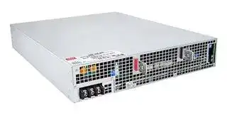
Illustrative purposes only

SHP-30K-055
AC/DC Enclosed Power Supply (PSU), ITE & Industrial, 1 Outputs, 19 kW, 55 VDC, 346 A
⚠️ Reference pricing provided. In case of supply shortages, we will connect you with our trusted procurement partners to ensure your project's continuity.
- Manufacturer: MEAN WELL
- Product type: AC / DC Enclosed Power Supplies
- SVHC: No SVHC (25-Jun-2025)
- Product Range: SHP-30K-HV Series
- No. of Outputs: 1Outputs
- Output Power Max: 19kW
- Input Voltage VAC: 340V AC to 530V AC
- Power Supply Output Type: Programmable
- Output Current - Output 1: 346A
- Output Current - Output 2: -
- Output Current - Output 3: -
- Output Current - Output 4: -
- Output Voltage - Output 1: 55VDC
- Output Voltage - Output 2: -
- Output Voltage - Output 3: -
- Output Voltage - Output 4: -
- Power Supply Applications: ITE & Industrial
| Delivery and price | |
|---|---|
| Units per pack | 1 |
| Price | 6452.79 € |
| Current stock | 10+ |
| Lead time | 30 days |
Datasheet

30KW 3ψ3W High Efficiency Digital Power Supply **SHP-30K-HV series**

## Front

Back

BauarSicherheitbeegelodwacmat geprufto ges g www.ID 2000000000tuv.com HM wami[®][ Als] g ~~y:~~ **UL62368-1 EN62368-1 TPTC004 IEC62368-1** ■ Features ψ

## ■

## ■

SHP-30K-HV series is a 30KW 3 ψ 3W input AC/DC power supply. This series operates for the wide range three phase AC input (3 phase 3 wire / 340~530VAC) neutral is not needed, and offers the models with DC outputs (55V/115V/230V/380V) that mostly demanded by various industries. Can be working at ℃

**==> picture [13 x 11] intentionally omitted <==**

**----- Start of picture text -----**<br>
■<br>**----- End of picture text -----**<br>


_File Name:SHP-30K-HV-SPEC   2023-09-19_

30KW 3ψ3W High Efficiency Digital Power Supply **SHP-30K-HV series**

## **SPECIFICATION**

|**MODEL**<br>**DC VOLTAGE (factory default)**<br>**CURRENT (factory default)**<br>**CURRENT RANGE**<br>**RATED POWER (max.)**<br>**FULL POWER VOLTAGE RANGE**<br>**OUTPUT**<br>**VOLTAGE ADJ. RANGE**<br>**LINE REGULATION**<br>**LOAD REGULATION**<br>**SETUP, RISE TIME**<br>**HOLD UP TIME (Typ.)**<br>**VOLTAGE RANGE**<br>**Note.5**<br>**FREQUENCY RANGE**<br>**EFFICIENCY (Typ.)**<br>**Note.6**<br>**INPUT**<br>**INRUSH CURRENT (Typ.)**<br>**LEAKAGE CURRENT**<br>**OVER TEMPERATURE**<br>**WORKING TEMP.**<br>**WORKING HUMIDITY**<br>**STORAGE TEMP., HUMIDITY**<br>**TEMP. COEFFICIENT**<br>**VIBRATION**<br>**MTBF**<br>**DIMENSION**<br>**OTHERS**<br>**NOTE**<br>**PACKING**<br>**OVER LOAD**<br>**OVER VOLTAGE**<br>**AC CURRENT (Typ.)**<br>3000ms, 100ms at full load<br>20ms / 400VAC at 75% load          16ms / 400VAC at full load<br>3<br>3-wire / 340 ~ 530VAC<br>ψ<br>47 ~ 63Hz<br><13mA peak / 530VAC, <7mA rms / 530VAC<br>100 ~ 105% of rated current<br>Protection type : Constant current limiting, unit will shutdown after 5 sec. re-power on to recover<br>Protection type : Shut down o/p voltage, re-power on to recover<br>-30 ~ +70<br>(Refer to "Derating Curve")<br>℃<br>20 ~ 90% RH non-condensing<br>-40 ~ +85<br>, 10 ~ 95% RH non-condensing<br>℃<br>±<br>℃<br>℃<br>0.03%/<br>(0 ~ 50<br>)<br>10 ~ 500Hz, 2G 10min./1cycle, 60min. each along X, Y, Z axes<br>540*424*83.5mm (L*W*H)<br>23.4Kg; 1pcs/23.4Kg/2.82CUFT<br>188.1K hrs min.<br>Telcordia SR-332 (Bellcore) ; 20.9K hrs min.      MIL-HDBK-217F (25<br>)<br>℃<br>96%<br>47A/400VAC         39A/480VAC<br>95%<br>60A/400VAC         80A/480VAC<br>30A/400VAC   25.2A/480VAC<br>145 ~ 166V<br>60.5 ~ 69.1V<br>96.5%<br>273 ~ 312V<br>97%<br>420 ~ 480V<br>±0.5%<br>±0.5%<br>±0.5%<br>±0.5%<br>±0.5%<br>±0.5%<br>±0.5%<br>±0.5%<br>±1.0%<br>±1.0%<br>±1.0%<br>±1.0%<br>1Vp-p<br>0.55Vp-p<br>1.5Vp-p<br>2Vp-p<br>90 ~ 138V<br>39 ~ 57.6V<br>170 ~ 260V<br>260 ~ 400V<br>115V<br>55V<br>230V<br>380V<br>261A<br>346A<br>130.5A<br>79A<br>0 ~ 261A<br>0 ~ 346A<br>0 ~ 139A<br>0 ~ 90A<br>30000W<br>19000W<br>115 ~ 138V<br>48 ~ 57.6V<br>216 ~ 260V<br>334 ~ 400V<br>30000W<br>30000W<br>**SHP-30K-115**<br>**SHP-30K-55**<br>**SHP-30K-230**<br>**SHP-30K-380**<br>**POWER FACTOR (Typ.)**<br>≧0.98/400VAC/480VAC at full load<br>**SAFETY STANDARDS**<br>UL62368-1, IEC62477, CAN/CSA C22.2<br>, TUV<br>EN62368-1, EAC TP TC 004 approved<br>BS EN/<br>No. 62368-1<br>**RIPPLE & NOISE (max.) Note.2**<br>**VOLTAGE TOLERANCE Note.3**<br>I/P-O/P:4.25KVAC     I/P-FG:3KVAC     O/P-FG:3KVAC<br>I/P-O/P, I/P-FG, O/P-FG:100M Ohms / 500VDC / 25<br>/ 70% RH<br>℃<br>**ENVIRONMENT**<br>**SAFETY &**<br>**FUNCTION**<br>**EMC**<br>**(Note 7)**<br>**PROTECTION**<br>Shut down o/p voltage, recovers automatically after temperature goes down<br>**Parameter**<br>**Parameter**<br>ESD<br>Radiated<br>EFT / Burst<br>Surge<br>Conducted<br>Magnetic Field<br>Voltage Dips and Interruptions<br>Conducted<br>Radiated<br>Harmonic Current<br>Voltage Flicker<br>EN55024 , EN61204-3, EN61000-6-2<br>**Standard**<br>**Standard**<br>BS EN/EN55032 (CISPR32) / EN55011 (CISPR11)<br>BS EN/EN55032 (CISPR32) / EN55011 (CISPR11)<br>BS EN/EN61000-3-2<br>BS EN/EN61000-3-3<br>BS EN/EN61000-4-2<br>BS EN/EN61000-4-3<br>BS EN/EN61000-4-4<br>BS EN/EN61000-4-5<br>BS EN/EN61000-4-6<br>BS EN/EN61000-4-8<br>BS EN/EN61000-4-11<br>**Test Level / Note**<br>**Test Level / Note**<br>Level 3, 8KV air ; Level 2, 4KV contact<br>Level 3<br>Level 3<br>Level 3<br>Level 4<br>>95% dip 0.5 periods, 30% dip 25 periods,<br>>95% interruptions 250 periods<br>Class A<br>Class A<br>-----<br>-----<br>**EMC IMMUNITY**<br>**EMC EMISSION**<br>**ALARM SIGNAL OUTPUT**<br>**REMOTE ON-OFF CONTROL**<br>**AUXILIARY POWER(AUX)**<br>Please refer to the function manual.<br>AC-OK,DC-OK, Fan Fail. Please refer to the function manual.<br>12V@1.5A tolerance<br>5%, ripple 150mVp-p<br>±<br>**CURRENT SHARING**<br>Up to 12 units or more. Please refer to the Current share derating curve<br>**OUTPUT VOLTAGE PROGRAMMABLE**<br>Can be adjusted via built-in potentiometer<br>Adjustment of output voltage is allowable between 50 ~ 120% of nominal output voltage. Please refer to the PV curve function manual<br>Adjustment of constant current level is allowable between 1 ~ 100% of rated current. Please refer to the PC<br>function manual<br>curve<br>**CONSTANT CURRENT LEVEL PROGRAMMABLE**<br>Level 4, 4KV/Line-Earth ; Level 3, 2KV/Line-Line<br>**DC-OK SIGNAL**<br>The TTL signal output, PSU turn on = -0.5 ~ 0.5V ; PSU turn off = 3.5 ~ 5.5V.  Please refer to the function manual<br>℃<br>ncludes set up tolerance,<br>derating curve<br>http://www.meanwell.com)<br>℃<br>℃<br>Under light load condition, output voltage ripple will exceed specification. The behavior can be minimized by increasing the load.<br>※<br>:<br>https://www.meanwell.com/serviceDisclaimer.aspx<br>**WITHSTAND VOLTAGE Note.4**<br>**ISOLATION RESISTANCE Note.4**<br>1. All parameters NOT specially mentioned are measured at400VAC input, rated load and 25__ of ambient temperature.<br>2. Ripple & noise are measured at 20MHz of bandwidth by using a 12" twisted pair-wire terminated with a 0.1uf & 47uf parallel capacitor.<br>3. Tolerance<br>line regulation and load regulation.<br>4. During withstand voltage and isolation resistance testing, the screw “A” shall be temporarily removed, and shall be installed back after the testing.<br>5. Derating may be needed under low input voltages. Please check the<br>for more details.<br>6. The efficiency is measured at 75% load and 480VAC input.<br>7. The power supply is considered a component which will be installed into a final equipment. All the EMC tests are been executed by mounting the unit on<br>a 600mm*900mm metal plate with 1mm of thickness. The final equipment must be re-confirmed that it still meets EMC directives. For guidance on how to<br>perform these EMC tests, please refer to “EMI testing of component power supplies.” (as available on<br>8. The ambient temperature derating of 3.5<br>/1000m with fanless models and of 5<br>/1000m with fan models for operating altitude higher than 2000m(6500ft).<br>9. If use PV signal to adjust Vo, under certain operations conditions, ripple noise of Vo might slightly go over rating defined in this specification.<br>10<br>Product Liability Disclaimer<br>For detailed information, please refer to|**MODEL**<br>**DC VOLTAGE (factory default)**<br>**CURRENT (factory default)**<br>**CURRENT RANGE**<br>**RATED POWER (max.)**<br>**FULL POWER VOLTAGE RANGE**<br>**OUTPUT**<br>**VOLTAGE ADJ. RANGE**<br>**LINE REGULATION**<br>**LOAD REGULATION**<br>**SETUP, RISE TIME**<br>**HOLD UP TIME (Typ.)**<br>**VOLTAGE RANGE**<br>**Note.5**<br>**FREQUENCY RANGE**<br>**EFFICIENCY (Typ.)**<br>**Note.6**<br>**INPUT**<br>**INRUSH CURRENT (Typ.)**<br>**LEAKAGE CURRENT**<br>**OVER TEMPERATURE**<br>**WORKING TEMP.**<br>**WORKING HUMIDITY**<br>**STORAGE TEMP., HUMIDITY**<br>**TEMP. COEFFICIENT**<br>**VIBRATION**<br>**MTBF**<br>**DIMENSION**<br>**OTHERS**<br>**NOTE**<br>**PACKING**<br>**OVER LOAD**<br>**OVER VOLTAGE**<br>**AC CURRENT (Typ.)**<br>3000ms, 100ms at full load<br>20ms / 400VAC at 75% load          16ms / 400VAC at full load<br>3<br>3-wire / 340 ~ 530VAC<br>ψ<br>47 ~ 63Hz<br><13mA peak / 530VAC, <7mA rms / 530VAC<br>100 ~ 105% of rated current<br>Protection type : Constant current limiting, unit will shutdown after 5 sec. re-power on to recover<br>Protection type : Shut down o/p voltage, re-power on to recover<br>-30 ~ +70<br>(Refer to "Derating Curve")<br>℃<br>20 ~ 90% RH non-condensing<br>-40 ~ +85<br>, 10 ~ 95% RH non-condensing<br>℃<br>±<br>℃<br>℃<br>0.03%/<br>(0 ~ 50<br>)<br>10 ~ 500Hz, 2G 10min./1cycle, 60min. each along X, Y, Z axes<br>540*424*83.5mm (L*W*H)<br>23.4Kg; 1pcs/23.4Kg/2.82CUFT<br>188.1K hrs min.<br>Telcordia SR-332 (Bellcore) ; 20.9K hrs min.      MIL-HDBK-217F (25<br>)<br>℃<br>96%<br>47A/400VAC         39A/480VAC<br>95%<br>60A/400VAC         80A/480VAC<br>30A/400VAC   25.2A/480VAC<br>145 ~ 166V<br>60.5 ~ 69.1V<br>96.5%<br>273 ~ 312V<br>97%<br>420 ~ 480V<br>±0.5%<br>±0.5%<br>±0.5%<br>±0.5%<br>±0.5%<br>±0.5%<br>±0.5%<br>±0.5%<br>±1.0%<br>±1.0%<br>±1.0%<br>±1.0%<br>1Vp-p<br>0.55Vp-p<br>1.5Vp-p<br>2Vp-p<br>90 ~ 138V<br>39 ~ 57.6V<br>170 ~ 260V<br>260 ~ 400V<br>115V<br>55V<br>230V<br>380V<br>261A<br>346A<br>130.5A<br>79A<br>0 ~ 261A<br>0 ~ 346A<br>0 ~ 139A<br>0 ~ 90A<br>30000W<br>19000W<br>115 ~ 138V<br>48 ~ 57.6V<br>216 ~ 260V<br>334 ~ 400V<br>30000W<br>30000W<br>**SHP-30K-115**<br>**SHP-30K-55**<br>**SHP-30K-230**<br>**SHP-30K-380**<br>**POWER FACTOR (Typ.)**<br>≧0.98/400VAC/480VAC at full load<br>**SAFETY STANDARDS**<br>UL62368-1, IEC62477, CAN/CSA C22.2<br>, TUV<br>EN62368-1, EAC TP TC 004 approved<br>BS EN/<br>No. 62368-1<br>**RIPPLE & NOISE (max.) Note.2**<br>**VOLTAGE TOLERANCE Note.3**<br>I/P-O/P:4.25KVAC     I/P-FG:3KVAC     O/P-FG:3KVAC<br>I/P-O/P, I/P-FG, O/P-FG:100M Ohms / 500VDC / 25<br>/ 70% RH<br>℃<br>**ENVIRONMENT**<br>**SAFETY &**<br>**FUNCTION**<br>**EMC**<br>**(Note 7)**<br>**PROTECTION**<br>Shut down o/p voltage, recovers automatically after temperature goes down<br>**Parameter**<br>**Parameter**<br>ESD<br>Radiated<br>EFT / Burst<br>Surge<br>Conducted<br>Magnetic Field<br>Voltage Dips and Interruptions<br>Conducted<br>Radiated<br>Harmonic Current<br>Voltage Flicker<br>EN55024 , EN61204-3, EN61000-6-2<br>**Standard**<br>**Standard**<br>BS EN/EN55032 (CISPR32) / EN55011 (CISPR11)<br>BS EN/EN55032 (CISPR32) / EN55011 (CISPR11)<br>BS EN/EN61000-3-2<br>BS EN/EN61000-3-3<br>BS EN/EN61000-4-2<br>BS EN/EN61000-4-3<br>BS EN/EN61000-4-4<br>BS EN/EN61000-4-5<br>BS EN/EN61000-4-6<br>BS EN/EN61000-4-8<br>BS EN/EN61000-4-11<br>**Test Level / Note**<br>**Test Level / Note**<br>Level 3, 8KV air ; Level 2, 4KV contact<br>Level 3<br>Level 3<br>Level 3<br>Level 4<br>>95% dip 0.5 periods, 30% dip 25 periods,<br>>95% interruptions 250 periods<br>Class A<br>Class A<br>-----<br>-----<br>**EMC IMMUNITY**<br>**EMC EMISSION**<br>**ALARM SIGNAL OUTPUT**<br>**REMOTE ON-OFF CONTROL**<br>**AUXILIARY POWER(AUX)**<br>Please refer to the function manual.<br>AC-OK,DC-OK, Fan Fail. Please refer to the function manual.<br>12V@1.5A tolerance<br>5%, ripple 150mVp-p<br>±<br>**CURRENT SHARING**<br>Up to 12 units or more. Please refer to the Current share derating curve<br>**OUTPUT VOLTAGE PROGRAMMABLE**<br>Can be adjusted via built-in potentiometer<br>Adjustment of output voltage is allowable between 50 ~ 120% of nominal output voltage. Please refer to the PV curve function manual<br>Adjustment of constant current level is allowable between 1 ~ 100% of rated current. Please refer to the PC<br>function manual<br>curve<br>**CONSTANT CURRENT LEVEL PROGRAMMABLE**<br>Level 4, 4KV/Line-Earth ; Level 3, 2KV/Line-Line<br>**DC-OK SIGNAL**<br>The TTL signal output, PSU turn on = -0.5 ~ 0.5V ; PSU turn off = 3.5 ~ 5.5V.  Please refer to the function manual<br>℃<br>ncludes set up tolerance,<br>derating curve<br>http://www.meanwell.com)<br>℃<br>℃<br>Under light load condition, output voltage ripple will exceed specification. The behavior can be minimized by increasing the load.<br>※<br>:<br>https://www.meanwell.com/serviceDisclaimer.aspx<br>**WITHSTAND VOLTAGE Note.4**<br>**ISOLATION RESISTANCE Note.4**<br>1. All parameters NOT specially mentioned are measured at400VAC input, rated load and 25__ of ambient temperature.<br>2. Ripple & noise are measured at 20MHz of bandwidth by using a 12" twisted pair-wire terminated with a 0.1uf & 47uf parallel capacitor.<br>3. Tolerance<br>line regulation and load regulation.<br>4. During withstand voltage and isolation resistance testing, the screw “A” shall be temporarily removed, and shall be installed back after the testing.<br>5. Derating may be needed under low input voltages. Please check the<br>for more details.<br>6. The efficiency is measured at 75% load and 480VAC input.<br>7. The power supply is considered a component which will be installed into a final equipment. All the EMC tests are been executed by mounting the unit on<br>a 600mm*900mm metal plate with 1mm of thickness. The final equipment must be re-confirmed that it still meets EMC directives. For guidance on how to<br>perform these EMC tests, please refer to “EMI testing of component power supplies.” (as available on<br>8. The ambient temperature derating of 3.5<br>/1000m with fanless models and of 5<br>/1000m with fan models for operating altitude higher than 2000m(6500ft).<br>9. If use PV signal to adjust Vo, under certain operations conditions, ripple noise of Vo might slightly go over rating defined in this specification.<br>10<br>Product Liability Disclaimer<br>For detailed information, please refer to|**SHP-30K-55**|**SHP-30K-115**|**SHP-30K-115**|**SHP-30K-230**|**SHP-30K-230**|**SHP-30K-380**|
|---|---|---|---|---|---|---|---|
||**DC VOLTAGE (factory default)**|55V|115V||230V||380V|
||**CURRENT (factory default)**|346A|261A||130.5A||79A|
||**CURRENT RANGE**|0 ~ 346A|0 ~ 261A||0 ~ 139A||0 ~ 90A|
||**RATED POWER (max.)**|19000W|30000W||30000W||30000W|
||**FULL POWER VOLTAGE RANGE**|48 ~ 57.6V|115 ~ 138V||216 ~ 260V||334 ~ 400V|
||**RIPPLE & NOISE (max.) Note.2**|0.55Vp-p|1Vp-p||1.5Vp-p||2Vp-p|
||**VOLTAGE ADJ. RANGE**|90 ~ 138V<br>39 ~ 57.6V<br>170 ~ 260V<br>260 ~ 400V<br>Can be adjusted via built-in potentiometer||||||
||**VOLTAGE TOLERANCE Note.3**|±1.0%|±1.0%||±1.0%||±1.0%|
||**LINE REGULATION**|±0.5%|±0.5%||±0.5%||±0.5%|
||**LOAD REGULATION**|±0.5%|±0.5%||±0.5%||±0.5%|
||**SETUP, RISE TIME**|3000ms, 100ms at full load||||||
||**HOLD UP TIME (Typ.)**|20ms / 400VAC at 75% load          16ms / 400VAC at full load||||||
||**VOLTAGE RANGE**<br>**Note.5**|3<br>3-wire / 340 ~ 530VAC<br>ψ||||||
||**FREQUENCY RANGE**|47 ~ 63Hz||||||
||**POWER FACTOR (Typ.)**|≧0.98/400VAC/480VAC at full load||||||
||**EFFICIENCY (Typ.)**<br>**Note.6**|95%|96%||96.5%||97%|
||**AC CURRENT (Typ.)**|30A/400VAC   25.2A/480VAC|47A/400VAC         39A/480VAC|||||
||**INRUSH CURRENT (Typ.)**|60A/400VAC         80A/480VAC||||||
||**LEAKAGE CURRENT**|<13mA peak / 530VAC, <7mA rms / 530VAC||||||
||**OVER LOAD**|100 ~ 105% of rated current<br>Protection type : Constant current limiting, unit will shutdown after 5 sec. re-power on to recover||||||
||**OVER VOLTAGE**|Protection type : Shut down o/p voltage, re-power on to recover<br>145 ~ 166V<br>60.5 ~ 69.1V<br>273 ~ 312V<br>420 ~ 480V||||||
||**OVER TEMPERATURE**|Shut down o/p voltage, recovers automatically after temperature goes down||||||
||**CURRENT SHARING**|Up to 12 units or more. Please refer to the Current share derating curve||||||
||**OUTPUT VOLTAGE PROGRAMMABLE**|Adjustment of output voltage is allowable between 50 ~ 120% of nominal output voltage. Please refer to the PV curve function manual||||||
||**CONSTANT CURRENT LEVEL PROGRAMMABLE**|Adjustment of constant current level is allowable between 1 ~ 100% of rated current. Please refer to the PC<br>function manual<br>curve||||||
||**AUXILIARY POWER(AUX)**|12V@1.5A tolerance<br>5%, ripple 150mVp-p<br>±||||||
||**REMOTE ON-OFF CONTROL**|Please refer to the function manual.||||||
||**ALARM SIGNAL OUTPUT**|AC-OK,DC-OK, Fan Fail. Please refer to the function manual.||||||
||**DC-OK SIGNAL**|The TTL signal output, PSU turn on = -0.5 ~ 0.5V ; PSU turn off = 3.5 ~ 5.5V.  Please refer to the function manual||||||
||**WORKING TEMP.**|-30 ~ +70<br>(Refer to "Derating Curve")<br>℃||||||
||**WORKING HUMIDITY**|20 ~ 90% RH non-condensing||||||
||**STORAGE TEMP., HUMIDITY**|-40 ~ +85<br>, 10 ~ 95% RH non-condensing<br>℃||||||
||**TEMP. COEFFICIENT**|±<br>℃<br>℃<br>0.03%/<br>(0 ~ 50<br>)||||||
||**VIBRATION**|10 ~ 500Hz, 2G 10min./1cycle, 60min. each along X, Y, Z axes||||||
||**SAFETY STANDARDS**|UL62368-1, IEC62477, CAN/CSA C22.2<br>, TUV<br>EN62368-1, EAC TP TC 004 approved<br>BS EN/<br>No. 62368-1||||||
||**WITHSTAND VOLTAGE Note.4**|I/P-O/P:4.25KVAC     I/P-FG:3KVAC     O/P-FG:3KVAC||||||
||**ISOLATION RESISTANCE Note.4**|I/P-O/P, I/P-FG, O/P-FG:100M Ohms / 500VDC / 25<br>/ 70% RH<br>℃||||||
||**MTBF**<br>**EMC IMMUNITY**<br>**EMC EMISSION**|**Parameter**||**Standard**||**Test Level / Note**||
|||Conducted||BS EN/EN55032 (CISPR32) / EN55011 (CISPR11)||Class A||
|||Radiated||BS EN/EN55032 (CISPR32) / EN55011 (CISPR11)||Class A||
|||Harmonic Current||BS EN/EN61000-3-2||-----||
|||Voltage Flicker||BS EN/EN61000-3-3||-----||
|||EN55024 , EN61204-3, EN61000-6-2||||||
|||**Parameter**||**Standard**||**Test Level / Note**||
|||ESD||BS EN/EN61000-4-2||Level 3, 8KV air ; Level 2, 4KV contact||
|||Radiated||BS EN/EN61000-4-3||Level 3||
|||EFT / Burst||BS EN/EN61000-4-4||Level 3||
|||Surge||BS EN/EN61000-4-5||Level 4, 4KV/Line-Earth ; Level 3, 2KV/Line-Line||
|||Conducted||BS EN/EN61000-4-6||Level 3||
|||Magnetic Field||BS EN/EN61000-4-8||Level 4||
|||Voltage Dips and Interruptions||BS EN/EN61000-4-11||>95% dip 0.5 periods, 30% dip 25 periods,<br>>95% interruptions 250 periods||
|||188.1K hrs min.<br>Telcordia SR-332 (Bellcore) ; 20.9K hrs min.      MIL-HDBK-217F (25<br>)<br>℃||||||
||**DIMENSION**|540*424*83.5mm (L*W*H)||||||
||**PACKING**<br>23.4Kg; 1pcs/23.4Kg/2.82CUFT<br>℃<br>ncludes set up tolerance,<br>derating curve<br>http://www.meanwell.com)<br>℃<br>℃<br>Under light load condition, output voltage ripple will exceed specification. The behavior can be minimized by increasing the load.<br>※<br>:<br>https://www.meanwell.com/serviceDisclaimer.aspx<br>1. All parameters NOT specially mentioned are measured at400VAC input, rated load and 25__ of ambient temperature.<br>2. Ripple & noise are measured at 20MHz of bandwidth by using a 12" twisted pair-wire terminated with a 0.1uf & 47uf parallel capacitor.<br>3. Tolerance<br>line regulation and load regulation.<br>4. During withstand voltage and isolation resistance testing, the screw “A” shall be temporarily removed, and shall be installed back after the testing.<br>5. Derating may be needed under low input voltages. Please check the<br>for more details.<br>6. The efficiency is measured at 75% load and 480VAC input.<br>7. The power supply is considered a component which will be installed into a final equipment. All the EMC tests are been executed by mounting the unit on<br>a 600mm*900mm metal plate with 1mm of thickness. The final equipment must be re-confirmed that it still meets EMC directives. For guidance on how to<br>perform these EMC tests, please refer to “EMI testing of component power supplies.” (as available on<br>8. The ambient temperature derating of 3.5<br>/1000m with fanless models and of 5<br>/1000m with fan models for operating altitude higher than 2000m(6500ft).<br>9. If use PV signal to adjust Vo, under certain operations conditions, ripple noise of Vo might slightly go over rating defined in this specification.<br>10<br>Product Liability Disclaimer<br>For detailed information, please refer to|||||||


“EMI testing of component power supplies.” (as available on http://www.meanwell.com) ℃ /1000m with fanless models and of 5 ℃ /1000m with fan models for operating altitude higher than 2000m(6500ft).

10 Under light load condition, output voltage ripple will exceed specification. The behavior can be minimized by increasing the load. ※ Product Liability Disclaimer : For detailed information, please refer to https://www.meanwell.com/serviceDisclaimer.aspx

_File Name:SHP-30K-HV-SPEC 2023-09-19_

## 30KW 3ψ3W High Efficiency Digital Power Supply **SHP-30K-HV series**

## **BLOCK DIAGRAM**

**==> picture [500 x 448] intentionally omitted <==**

**----- Start of picture text -----**<br>
PFC fosc : 80KHz<br>PWM fosc : 90KHz<br>EMI RECTIFIERS POWER RECTIFIERS +V<br>I/P & &<br>FILTER PFC SWITCHING FILTER -V<br>DETECTION PWM O.V.P.<br>CIRCUIT CONTROL<br>DETECTION<br>CIRCUIT<br>O.L.P.<br>PV/PC ENABLE<br>MCU ISOLATOR<br>O.T.P.<br>PV/PC<br>TRANSCEIVERS DA/DB<br>MCU<br>FAN-FAIL<br>POWERAUX ATORISOL MCU ISOLATIONDATA AC-OKT-ALARMDC-OK<br>(SDA/SCL)<br>(CANH/CANL)<br>RECTIFIERS AUX POWER (DATA+/DATA-)<br>&<br>FILTER (12V/1.5A)<br>REMOTE ON-OFF<br>FAN<br>DERATING CURVE<br>100<br>Others<br>80<br>60 55V<br>50<br>40<br>20<br>-30 0 10 20 30 40 45 50 60 70 (HORIZONTAL)<br>AMBIENT TEMPERATURE ( ℃ )<br>LOAD (%)<br>**----- End of picture text -----**<br>


_File Name:SHP-30K-HV-SPEC   2023-09-19_

30KW 3ψ3W High Efficiency Digital Power Supply **SHP-30K-HV series**

**==> picture [503 x 518] intentionally omitted <==**

**----- Start of picture text -----**<br>
STATIC CHARACTERISTICS EFFICIENCY VS LOAD (380V MODEL)<br>100<br>97<br>95<br>100<br>90<br>90<br>85<br>80 480VAC & 380VDC<br>80<br>70<br>75<br>60<br>70<br>50<br>65<br>10% 20% 30% 40% 50% 60% 70% 80% 90% 100%<br>340 360 380 400 420 440 460 480 500 525 530<br>LOAD<br>INPUT VOLTAGE (V) 60Hz<br>AC Power Connection<br>◎ψ3 3-wire / △ 340VAC~530VAC T SHP-30K<br>L3<br>L2<br>L1<br>S<br>R FG<br>Fig 1.1<br>◎ψ3 3-wire / Y 340VAC~530VAC<br>T SHP-30K<br>L3<br>L2<br>L1<br>S<br>FG<br>R<br>Fig 1.2<br>EFFICIENCY (%)<br>340V~530VAC<br>340V~530VAC<br>LOAD (%)<br>340V~530VAC<br>340V~530VAC<br>**----- End of picture text -----**<br>


_File Name:SHP-30K-HV-SPEC   2023-09-19_

30KW 3ψ3W High Efficiency Digital Power Supply **SHP-30K-HV series**

## **Function Manual**

- **1.Output Voltage Programming (or, PV / remote voltage programming / remote adjust / margin programming / dynamic voltage trim)**

- (1)Default by potentiometer (SVR) ON 1 2 3 (a)Have the DIP switch position-3 set as OFF (b)Output voltage can be trimmed by SVR.

- (2)By Output Voltage Programming ON 1 2 3 (a)Have the DIP switch position-3 set as OFF (b)The output voltage can be trimmed to 50~120% by applying EXTERNAL VOLTAGE between _PV+_ and _PV-_ on CN53.

**==> picture [448 x 434] intentionally omitted <==**

**----- Start of picture text -----**<br>
DIP SW1<br>SW1DIP CN86<br>CN53<br>SW51 (Fine adjustments)<br>SW52 (Main Adjustments)<br>-V<br>PIN1,2 -V(Signal)<br>LOAD<br>+V<br>PIN3,4 PV+<br>EXTERNAL VOLTAGE (DC)(0~5V)<br>Fig 1.1<br>Vout for 55V model<br>100<br>95.5<br>120<br>83.3<br>114.5113.7 55V(Default) 80<br>106.5 380V(Default) 70<br>100 230V115V(Default)(Default) 60<br>Non-Linear 40<br>50 20<br>V<br>24 43.2 48 55 57.6<br>V 55V<br>0 1 3.64 4 4.37 4.41 4.7 4.8 57.5 103.5 115 138<br>115V<br>EXTERNAL VOLTAGE (DC) 108 194.4 216 260<br>230V<br>◎ The 100% output voltage is 48/115/216/334V. 167 300.6 334 400 380V<br>OUTPUT VOLTAGE<br>OUTPUT  VOLTAGE(%)<br>OUTPUT CURRENT (%)<br>**----- End of picture text -----**<br>


- The rated current should change with the Output Voltage Programming accordingly.

**==> picture [18 x 7] intentionally omitted <==**

**----- Start of picture text -----**<br>
Fig 1.2<br>**----- End of picture text -----**<br>


_File Name:SHP-30K-HV-SPEC   2023-09-19_

30KW 3ψ3W High Efficiency Digital Power Supply **SHP-30K-HV series**

**==> picture [511 x 668] intentionally omitted <==**

**----- Start of picture text -----**<br>
2.Constant Current Programming (or, PC / remote current programming / dynamic current trim)<br>(1)Default Overload Protection(OLP) value ON 1 2 3<br>(a)Have the DIP switch position-2 set as OFF<br>(b)Output current is set default value.<br>(2)By Constant Current Level Programming ON 1 2 3<br>(a)Have the DIP switch position-2 set as OFF<br>(b)The constant current level can be trimmed to 1~100% of the rated current by applying EXTERNAL VOLTAGE between PC+ and PC- on CN53.<br>DIP SW1<br>SW1DIP CN86<br>CN53<br>SW51<br>SW52<br>-V<br>PIN1,2 -V(Signal)<br>LOAD<br>+V<br>PIN5,6 PC+<br>EXTERNAL VOLTAGE (DC)(0~5V)<br>Fig 2.1<br>※ Under PC function at wattage < 10KW, the power supply might enter burst mode and cause output unstable, please increase the load to minimized the effect.<br>※ Auto de-rating function covered by over temperature protection, it works either in PC mode or under control by communication protocol.<br>T1(Typ.): Maximum ambient temperature of full load.<br>T2(Typ.): T1+5℃.<br>Iout<br>110 100<br>100<br>80 Non-Linear<br>Non-Linear<br>60<br>50<br>40<br>1 20<br>V<br>0 0.047 4.7 4.8 T1 T2 (HORIZONTAL)<br>EXTERNAL VOLTAGE (DC) AMBIENT TEMPERATURE  ( ℃ )<br>◎ The 100% output current is 346/261/139/90A.<br>◎ It might cause higher current ripple when the output current<br>Fig 2.2<br>adjust below 20%(@<1V programming)<br>LOAD (%)<br>OUTPUT  CURRENT(%)<br>**----- End of picture text -----**<br>


_File Name:SHP-30K-HV-SPEC   2023-09-19_

30KW 3ψ3W High Efficiency Digital Power Supply **SHP-30K-HV series**

**==> picture [511 x 668] intentionally omitted <==**

**----- Start of picture text -----**<br>
3.DA, DB signal and parallel control function<br>(1)Non-parallel operation ON 1 2 3<br>(a)set the DIP switch of postion-1 as OFF<br>(b)By default, non-parallel operation.<br>(2)Default parallel operation ON 1 2 3<br>(a)set the DIP switch of postion-1 as OFF<br>(b)PSUs are configured in parallel operation.<br>DIP SW1<br>SW1DIP CN86<br>CN53<br>SW51<br>SW52<br>Fig 3.1<br>4.Remote ON-OFF Control<br>※ The power supply can be turned ON-OFF by using the "Remote ON-OFF" function.<br>Between Remote ON-OFF ( CN86  pin1 ) and 5V-AUX( CN86 pin 2) Output Status<br>Switch close (Short) power supply ON<br>Switch open (Open) power supply OFF<br>Table 4.1<br>SW1DIP CN86<br>CN53<br>SW51<br>SW52<br>Fig 4.1<br>PIN3 Remote ON-OFF PIN4 +5V-AUX<br>**----- End of picture text -----**<br>


_File Name:SHP-30K-HV-SPEC   2023-09-19_

30KW 3ψ3W High Efficiency Digital Power Supply **SHP-30K-HV series**

## **5.Alarm Signal Output**

※ There are 4 alarm signals, DC-OK, T-ALARM, Fan Fail and AC-OK, in TTL signal form, on CN86. These signals are isolated from output.

**==> picture [230 x 203] intentionally omitted <==**

**----- Start of picture text -----**<br>
SW1DIP CN86<br>CN53<br>SW51<br>SW52<br>PIN6,8,10,12 GND-AUX<br>PIN5 T-ALARM<br>Application<br>Circuit<br>PIN7 Fan Fail<br>PIN9 DC-OK<br>PIN11 AC-OK<br>Fig 5.1<br>**----- End of picture text -----**<br>


|DC-OK & T-ALARM & Fan Fail Signal|Power Supply Status|
|---|---|
|“High” >3.5~5.5V|OFF|
|“Low” <-0.5~0.5V|ON|
|||
|AC-OK Signal|Power Supply Status|
|“High” >3.5~5.5V|ON|
|“Low” <-0.5~0.5V|OFF|


※ DC OK might mis-triggered when the voltage difference between PSU and the load, please minimized the unnecessary voltage difference.

_File Name:SHP-30K-HV-SPEC   2023-09-19_

30KW 3ψ3W High Efficiency Digital Power Supply **SHP-30K-HV series**

## **6.Current Sharing**

SHP-30K-HV has the built-in active current sharing function and can be connected in parallel, up to 12 units or more, to provide higher output power as exhibited below :

- ※ The power supplies should be paralleled using short and large diameter wiring and then connected to the load.

- ※ In parallel connection, power supply with the highest output Voltage will be the master unit and its Vout will be the DC bus voltage.

- ※ The total output current must not exceed the value determined  by the following equation: Maximum output current at parallel operation = (Rated current per unit) x (Number of unit) x 95%;when parallel unit less than 4. Maximum output current at parallel operation = (Rated current per unit) x (Number of unit) x [95% - (Number of unit - 4) x 2%];when parallel unit more than 5.

- ※ When the total output current is less than 5% of the total rated current, or say (5% of Rated current per unit)×(Number of unit) the current shared among units may not be balanced. (Please refer to the current share dreating curve)

- ※ Under parallel operation ripple of the output voltage may be higher than the SPEC at light load condition. It will go back to normal ripple level once the output load is more than 5%.

- ※ CN53/SW1 Function pin connection

**==> picture [475 x 504] intentionally omitted <==**

**----- Start of picture text -----**<br>
PSU1 PSU2 PSU3 PSU4 PSU5 PSU6 PSU7 PSU8 PSU9 PSU10 PSU11 PSU12<br>Parallel eG (O(n (GO<br>CN53 SW1 PIN1 CN53 SW1 PIN1 CN53 SW1 PIN1 CN53 SW1 PIN1 CN53 SW1 PIN1 CN53 SW1 PIN1 CN53 SW1 PIN1 CN53 SW1 PIN1 CN53 SW1 PIN1 CN53 SW1 PIN1 CN53 SW1 PIN1 CN53 SW1 PIN1<br>ye a oT E—=EEq  EE<br>Poof 1 unit X f t ON<br>2 unit V ON V ON<br>pt r<br>3 unit V ON V OFF V ON<br>fof TT<br>4 unit V ON V OFF V OFF V ON<br>pt | tf fF ft ft ft tt<br>5 unit V ON V OFF V OFF V OFF V ON<br>fF of  Te | tf fF ft tf ft ft<br>se 6 unit V ON ee V OFF QQ V OFF V OFF GN V OFF GG V ON COG GS OO GG<br>ff 7 unit V | ON tf V fF OFF ft V ft OFF ft V OFF V OFF V OFF V ON<br>Qe 8 unit V Ge ON V OFF GG V OFF V OFF V GGG OFF V OFF V OFF GGG V ON GO OG<br>ff 9 unit V | ON [| V fF OFF ft V ft OFF ft V ft OFF tf V ft OFF ft V ft OFF hm V OFF V OFF V ON<br>eG 10 unit V ON V GGG OFF V OFF V OFF V GGG OFF V OFF V OFF GO V GG OFF V I OFF V GO ON OG<br>ff 11 unit V | ON [| V Ff OFF ft V ft OFF ft V tf OFF tf V ft OFF ft V ft OFF tT V mm OFF V OFF V OFF V OFF V ON<br>bt 12 unit V tr ON V OFF V OFF V OFF V OFF V OFF V OFF V OFF V OFF V OFF V OFF V ON<br>(V : CN53 connected ; X : CN53 not connected.)<br>PSU1 PSU2 PSU11 PSU12<br>ana e: e — s aa e- e area l ....... a e= ee ee ao ee-<br>o<br>[pe —~ foe —e ~~ p<br> n— la = : ata a i [a]<br>+V -V<br>LOAD<br>Fig 6.1<br>7 9 7 9 7 9 7 9<br>DB DA DB DA .......... DB DA DB DA<br>PSU1 PSU2 PSU11 PSU12<br>CN53 DB DA CN53 DB DA CN53 DB DA CN53 DB DA<br>8 10 8 10 8 10 8 10<br>If the lines of CN53 are too long, they should<br>be twisted in pairs to avoid the noise.<br>◎ DA,DB are connected mutually in parallel.<br>∣ ∣ ∣ ∣ ∣ ∣ ∣ ∣ ∣ ∣ ∣ ∣ ∣ ∣ ∣ ∣ ∣ ∣ ∣ ∣ ∣ ∣<br>∣ ∣ ∣ ∣ ∣ ∣ ∣ ∣ ∣ ∣ ∣ ∣ ∣ ∣ ∣ ∣ ∣ ∣ ∣ ∣<br>∣ ∣ ∣ ∣ ∣ ∣ ∣ ∣ ∣ ∣ ∣ ∣ ∣ ∣ ∣ ∣ ∣ ∣<br>∣ ∣ ∣ ∣ ∣ ∣ ∣ ∣ ∣ ∣ ∣ ∣ ∣ ∣ ∣ ∣<br>∣ ∣ ∣ ∣ ∣ ∣ ∣ ∣ ∣ ∣ ∣ ∣ ∣ ∣<br>∣ ∣ ∣ ∣ ∣ ∣ ∣ ∣ ∣ ∣ ∣ ∣<br>∣ ∣ ∣ ∣ ∣ ∣ ∣ ∣ ∣ ∣<br>∣ ∣ ∣ ∣ ∣ ∣ ∣ ∣<br>∣ ∣ ∣ ∣ ∣ ∣<br>∣ ∣ ∣ ∣<br>∣ ∣<br>**----- End of picture text -----**<br>


_File Name:SHP-30K-HV-SPEC   2023-09-19_

30KW 3ψ3W High Efficiency Digital Power Supply **SHP-30K-HV series**

**==> picture [331 x 192] intentionally omitted <==**

**----- Start of picture text -----**<br>
Mechanical SpecificationCurrent Share Derating Curve<br>Total load<br>95%<br>79%<br>Units (Parallel Connection)<br>1 2 3 4 5 6 7 8 9 10 11 12<br>**----- End of picture text -----**<br>


## **Typical Application**

System power or Energy Backup System Configuration Cabinet(285KW)

**==> picture [472 x 359] intentionally omitted <==**

**----- Start of picture text -----**<br>
450 750<br>A ���� ���������������� E<br>B<br>D F<br>C<br>G<br>(Front View) (Side View) (Back View)<br>Item Description Item Description<br>A CMU2 Smart Controller E AC Input Circuit Breaker<br>B SHP-30K-HV Power Supply F DC Output Terminal<br>C 30U Cabinet G AC Input Terminal Block<br>D RJ-45 port<br>1579<br>!<br>**----- End of picture text -----**<br>


◎ For more system power or solutions, please visit our virtual Expo C3.3+N product hall. ◎ Any further request, please contact MEAN WELL sales team.

_File Name:SHP-30K-HV-SPEC   2023-09-19_

## 30KW 3ψ3W High Efficiency Digital Power Supply **SHP-30K-HV series**

**==> picture [511 x 668] intentionally omitted <==**

**----- Start of picture text -----**<br>
Mechanical Specification Case No.234B     Unit:mm<br>540<br>488 21 40 max.<br>1 CN53 CN86<br>1 1 3 5 7 9 20 18 16 14 1210 8 6 4 2<br>2 4 6 8 10 19 17 15 13 11 9 7 5 3 1<br>4-M4 L=5mm 1<br>68.75 7.4<br>SW51 SW52<br>434 75<br>20 2 SW51 SW52<br>DIP-SW1  2  319 12 CN53CN86109 LED1 SVR SVR<br>+V<br>Air flow<br>direction<br>-V<br>10 max. FG M5<br>TB1<br>1<br>4-M4 L=5mm 2<br>3<br>15 max. Screw "A"<br>(Note.4)<br>7 7.1<br>540<br>488 21<br>4-M4<br>1<br>1<br>4-M4 L=5mm 1<br>※ Mounting Instruction Chassis of SHP-30K<br>Hole No. Recommended Screw Size MAX. Penetration Depth  L Recommended mounting torque Mounting Surface<br>1 M4 5mm 7~1  K0 gf-cm<br>Mounting Screw<br>L<br>2<br>-ψ<br>8.5<br>10.2<br>12<br>16<br>38 83.5<br>25<br>38<br>46.75 46.75<br>3<br>331.6 331.6 424<br>483.6 466.1<br>22.7<br>22.7<br>**----- End of picture text -----**<br>


_File Name:SHP-30K-HV-SPEC   2023-09-19_

30KW 3ψ3W High Efficiency Digital Power Supply **SHP-30K-HV series**

|※Control Pin No. Assignment<br>: HRS DF11-10DP-2DS or equivalent<br>(<br>3)<br>CN5|※Control Pin No. Assignment<br>: HRS DF11-10DP-2DS or equivalent<br>(<br>3)<br>CN5|※Control Pin No. Assignment<br>: HRS DF11-10DP-2DS or equivalent<br>(<br>3)<br>CN5|※Control Pin No. Assignment<br>: HRS DF11-10DP-2DS or equivalent<br>(<br>3)<br>CN5|※Control Pin No. Assignment<br>: HRS DF11-10DP-2DS or equivalent<br>(<br>3)<br>CN5|※Control Pin No. Assignment<br>: HRS DF11-10DP-2DS or equivalent<br>(<br>3)<br>CN5|※Control Pin No. Assignment<br>: HRS DF11-10DP-2DS or equivalent<br>(<br>3)<br>CN5|※Control Pin No. Assignment<br>: HRS DF11-10DP-2DS or equivalent<br>(<br>3)<br>CN5|||
|---|---|---|---|---|---|---|---|---|---|
|1|||9|||||||
||||||||Mating Housing<br>HRS DF11-10DS or equivalent|||
||||||||Terminal<br>HRS DF11-**SC or equivalent|||
|2|||10|||||||
|Pin No.|||||Function||Description|||
|1,2||||-V(Signal)|||Negative output voltage signal. It is for local sense and certain function reference; it cannot be connected directly to the load.|||
|3,4|||||PV+||Connection for output voltage programming. (Note)|||
|5,6|||||PC+||Connection for constant current level programming. (Note)|||
|7,8|||||DB||Differential digital signal for parallel control. (Note)|||
|9,10|||||DA||Differential digital signal for parallel control. (Note)|||
|Note: Non-isolated signal,|||||||referenced to [-V(Signal)].|||
|※Control Pin No. Assignment<br>: HRS DF11-20DP-2DS or equivalent<br>(<br>)<br>CN86||||||||||
|20|||||2|||||
||||||||Mating Housing<br>HRS DF11-20DS or equivalent|||
||||||||Terminal<br>HRS DF11-**SC or equivalent|||
|19|||||1|||||
|**Pin No.**|||||**Function**||**Description**|||
|1,2|||||RL||Short: Termination resistors(120<br>) For CANBus<br>MODBus<br>Communication, please use Jumper (pin1,2)<br>Ω<br>、<br>、|||
|3|||||Remote<br>ON-OFF||The unit can turn the output ON/OFF by dry contact between Remote ON/OFF and +5-AUX.(Note)<br>Short (4.5 ~ 5.5V) : Power ON ; Open(0 ~ 0.5V) : Power OFF ; The maximum input voltage is 5.5V|||
|4|||||+5V-AUX||Auxiliary voltage output, 4.5~5.5V, referenced to GND-AUX (pin 6,8,10,12,19,20) only for Remote ON/OFF used. This output is not|||
||||||||controlled by the Remote ON/OFF control.|||
||||||||High (3.5 ~ 5.5V) : When the internal temperature exceeds the limit of temperature alarm.|||
|5|||||T-ALARM||Low (-0.5 ~ 0.5V) : When the internal temperature is normal.|||
||||||||The maximum sourcing current is 10mA and only for output.(Note)|||
|6,8,10,12|||||GND-AUX||Auxiliary voltage output GND.<br>The signal return is isolated from the output terminals (+V & -V).|||
||||||||High(3.5~5.5V):When the fan fail.|||
|7|||||Fan Fail||Low(-0.5~0.5V):When the fan works normally.|||
||||||||The maximum sourcing current is 10mA and only for output.(Note)|||
||||||||High(3.5 ~ 5.5V) :  When Vout<br>80%<br>6%.<br>≦<br>±|||
|9|||||DC-OK||Low(-0.5 ~ 0.5V) :  When Vout<br>80%<br>6%.<br>≧<br>±|||
||||||||The maximum sourcing current is 10mA and only for output.(Note)|||
||||||||High (3.5 ~ 5.5V): When AC input<br>335<br>≧<br>±1.5%Vac, PSU works normally.|||
|11|||||AC-OK||Low (-0.5 ~ 0.5V): When AC input<br>3<br>≦<br>±<br>20<br>1.5%Vac, PSU shut down.|||
||||||||The maximum sourcing current is 10mA and only for output.(Note)|||
||||||||For PMBus model: Serial Clock used in the PMBus interface.(Note)|||
|13,14||||For CANBus model: Data line used in CANBus interface.(Note)<br>SCL/CANL/<br>DATA-||||||
||||||||For MODBus model: Data line used in MODBus interface.(Note)|||
||||||||For PMBus model: Serial Data used in the PMBus interface.(Note)|||
|15,16|||For CANBus model: Data line used in CANBus interface.(Note)<br>SDA/CANH/<br>DATA+|||||||
||||||||For MODBus model: Data line used in MODBus interface.(Note)|||
|17,18|||||+12V-AUX||Auxiliary voltage output, 11.4~12.6V, referenced to GND-AUX (pin19 & 20).<br>The maximum load current is 1.5A. This output is not controlled by “Remote ON-OFF”.|||
|19,20|||||GND-AUX||Auxiliary voltage output GND.<br>The signal return is isolated from the output terminals(+V & -V).|||
|Note: Isolated||||signal, referenced to(GND-AUX).||||||


_File Name:SHP-30K-HV-SPEC   2023-09-19_

## 30KW 3ψ3W High Efficiency Digital Power Supply **SHP-30K-HV series**

## ※ LED Status Indicators

LED Description Green(LED1) LED on when output voltage is OK Red(LED2) LED on when any protection occurs ※ AC Input Terminal Pin No. Assignment (TB1) Pin No. Assignment Diagram Maximum mounting torque 1 AC/L1 2 AC/L2 18Kgf-cm 3 AC/L3 ※ DIP Switch Position Assignment(DIP-SW1): Please refer to the Function Manual. Pin No. Assignment Diagram 1 DA,DB Signal and paralled control function 1 2 3 2 Output Current Programming (PC) ON DIP-SW PIN2:PC OFF DIP-SW PIN3:PV 3 Output Voltage Programming (PV)

※SW51 and SW52 S.W For PMBus、CANBus、MODBus interface address setting, please refer to the user manual for more details

_File Name:SHP-30K-HV-SPEC   2023-09-19_
Updated at June 6, 2026
About Novapart
Novapart is a B2B electronic component broker specialising in stock shortages and cost reduction. We source hard-to-find parts and identify compliant alternatives across a catalogue of 410,000+ components from 500+ manufacturers.
Learn more →Stock Shortage Specialist
When a component is unavailable, discontinued or has an unacceptable lead time, we tap into our network of vetted European and Asian distributors to source what you need — without compromising on quality or traceability.
Request a quote →Compliant Alternatives
We identify pin-to-pin, electrically equivalent substitutes that meet the same certifications (RoHS, AEC-Q100, REACH) as your original specification — validated against datasheets, not just part numbers. Often at a lower cost.
BOM Analysis service →