
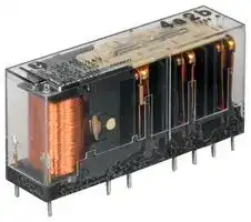


SFS6-DC24V
Safety Relay, 24 VDC, 3PST-NO, 3PST-NC, SF Series, Through Hole, 6 A, Solder
- Manufacturer: PANASONIC
- Product type: Safety Relays
- Coil Voltage:24VDC; Contact Configuration:3PST-NO, 3PST-NC; Product Range:SF Series; Relay Mounting:Through Hole; Contact Current:6A; Relay Terminals:Solder; Contact Voltage AC N
- SVHC: No SVHC (23-Jan-2024)
- IP Rating: -
- Coil Voltage: 24VDC
- Product Range: SF Series
- Relay Mounting: Through Hole
- Contact Current: 6A
- Relay Terminals: Solder
- Contact Material: Silver Tin Oxide
- Approvals & Standards: UL
- Contact Configuration: 3PST-NO, 3PST-NC
- Contact Voltage AC Nom: 250V
- Contact Voltage DC Nom: 30V
| Delivery and price | |
|---|---|
| Units per pack | 20 |
| Price | 14.5 € |
| Current stock | 200+ |
| Lead time | 30 days |
## **Slim type safety relays**

## **FEATURES**

**1. Acquisition of Korean safety certification (“S” mark)**

Excluding with diode type

**2. Forcibly guided contact structure**

**3. Slim profile (mm inch)**

- 40/50 (L) × 13 (W) × 24 (H)

- 1.575/1.969 (L) × .512 (W) × .945 (H)

## SF RELAYS Slim type

## **TYPICAL APPLICATIONS**

   **1. Machine tools**

   **2. Robots**

   **3. Safety PLCs**

   **4. Circuits with stringent safety standard requirements such as those in motor vehicle production equipment.**

**4. Fast response time is achieved (8 ms or less).**

**==> picture [85 x 21] intentionally omitted <==**

**----- Start of picture text -----**<br>
RoHS compliant<br>[<br>**----- End of picture text -----**<br>


Protective construction: Flux-resistant type

**5. With diode and LED indication type available**

**6. Sockets and terminal sockets (spade and ring tongue terminal compatible) are available.**

## **ORDERING INFORMATION**

**==> picture [138 x 25] intentionally omitted <==**

**----- Start of picture text -----**<br>
SF S<br>S: Slim type<br>**----- End of picture text -----**<br>


Contact arrangement

- 2: 2 Form A 2 Form B

- 3: 3 Form A 1 Form B

- 4: 4 Form A 2 Form B

- 5: 5 Form A 1 Form B

6: 3 Form A 3 Form B

Operation indication

Nil: Without LED indication L: With LED indication

Nominal coil voltage 12, 24, 48V DC

Function

Nil: None D: With diode

Notes: 1. Please consult us about other coil voltages. 2. LED indication color is green.

ASCTB119E   201507-T

–1–

SFS

## **TYPES**

## **1. Standard type**

|**TYPES**<br>**1. Standard type**|**TYPES**<br>**1. Standard type**||||
|---|---|---|---|---|
|Contact arrangement||Nominal coil voltage|Without LED indication|With LED indication|
||||Part No.|Part No.|
|4 poles|2 Form A 2 Form B<br>3 Form A 1 Form B|12 V DC|SFS2-DC12V|SFS2-L-DC12V|
|||24 V DC|SFS2-DC24V|SFS2-L-DC24V|
|||48 V DC|SFS2-DC48V|SFS2-L-DC48V|
|||12 V DC|SFS3-DC12V|SFS3-L-DC12V|
|||24 V DC|SFS3-DC24V|SFS3-L-DC24V|
|||48 V DC|SFS3-DC48V|SFS3-L-DC48V|
|6 poles|4 Form A 2 Form B<br>5 Form A 1 Form B<br>3 Form A 3 Form B|12 V DC|SFS4-DC12V|SFS4-L-DC12V|
|||24 V DC|SFS4-DC24V|SFS4-L-DC24V|
|||48 V DC|SFS4-DC48V|SFS4-L-DC48V|
|||12 V DC|SFS5-DC12V|SFS5-L-DC12V|
|||24 V DC|SFS5-DC24V|SFS5-L-DC24V|
|||48 V DC|SFS5-DC48V|SFS5-L-DC48V|
|||12 V DC|SFS6-DC12V|SFS6-L-DC12V|
|||24 V DC|SFS6-DC24V|SFS6-L-DC24V|
|||48 V DC|SFS6-DC48V|SFS6-L-DC48V|


Standard packing: Carton: 50 pcs.; Case: 200 pcs.

* Sockets and terminal sockets available.

## **2. With diode and LED indication type**

|Contact arrangement|Contact arrangement|Nominal coil voltage|Part No.|
|---|---|---|---|
|4 poles|2 Form A 2 Form B<br>3 Form A 1 Form B|12 V DC|SFS2-L-DC12V-D|
|||24 V DC|SFS2-L-DC24V-D|
|||48 V DC|SFS2-L-DC48V-D|
|||12 V DC|SFS3-L-DC12V-D|
|||24 V DC|SFS3-L-DC24V-D|
|||48 V DC|SFS3-L-DC48V-D|
|6 poles|4 Form A 2 Form B<br>5 Form A 1 Form B<br>3 Form A 3 Form B|12 V DC|SFS4-L-DC12V-D|
|||24 V DC|SFS4-L-DC24V-D|
|||48 V DC|SFS4-L-DC48V-D|
|||12 V DC|SFS5-L-DC12V-D|
|||24 V DC|SFS5-L-DC24V-D|
|||48 V DC|SFS5-L-DC48V-D|
|||12 V DC|SFS6-L-DC12V-D|
|||24 V DC|SFS6-L-DC24V-D|
|||48 V DC|SFS6-L-DC48V-D|


Standard packing: Carton: 50 pcs.; Case: 200 pcs.

* Sockets and terminal sockets available.

## **RATING**

## **1. Coil data**

|**RATING**<br>**1. Coil data**|**RATING**<br>**1. Coil data**||||||||
|---|---|---|---|---|---|---|---|---|
|Contact arrangement||Nominal coil<br>voltage|Pick-up voltage<br>(at 20°C68°F)|Drop-out voltage<br>(at 20°C68°F)|Nominal<br>operating current<br>[±10%]<br>(at 20°C68°F)|Coil resistance<br>[±10%]<br>(at 20°C68°F)|Nominal<br>operating power<br>(at 20°C68°F)|Max. applied<br>voltage<br>(at 20°C68°F)|
|4 poles|2 Form A 2 Form B|12V DC|75%V or less of<br>nominal voltage<br>(Initial)|10%V or more of<br>nominal voltage<br>(Initial)|30   mA|400Ω|Approx. 360mW|110%V of<br>nominal voltage|
|||24V DC|||15   mA|1,600Ω|||
|||48V DC|||7.5mA|6,400Ω|||
||3 Form A 1 Form B|12V DC|||30   mA|400Ω|||
|||24V DC|||15   mA|1,600Ω|||
|||48V DC|||7.5mA|6,400Ω|||
|6 poles|4 Form A 2 Form B|12V DC|||41.7mA|288Ω|Approx. 500mW||
|||24V DC|||20.8mA|1,152Ω|||
|||48V DC|||10.4mA|4,608Ω|||
||5 Form A 1 Form B|12V DC|||41.7mA|288Ω|||
|||24V DC|||20.8mA|1,152Ω|||
|||48V DC|||10.4mA|4,608Ω|||
||3 Form A 3 Form B|12V DC|||41.7mA|288Ω|||
|||24V DC|||20.8mA|1,152Ω|||
|||48V DC|||10.4mA|4,608Ω|||


Note: The nominal operating current will increase by approximately 2mA due to the LED on the LED indication type.

ASCTB119E   201507-T

–2–

SFS

## **2. Specifications (relay)**

|Characteristics|Item|Item|Specifcations|Specifcations|Specifcations|Specifcations|Specifcations|
|---|---|---|---|---|---|---|---|
||||4poles||6poles|||
|Contact|Contact arrangement||2 Form A 2 Form B|3 Form A 1 Form B|4 Form A 2 Form B|5 Form A 1 Form B|3 Form A 3 Form B|
||Contact resistance(Initial)||Max. 100 mΩ (Byvoltage drop6 V DC 1A)|||||
||Contact material||Au fashed AgSnO2type|||||
|Rating|Nominal switchingcapacity (resistive load)||6A 250V AC, 6A 30V DC|||||
||Max. switching power(resistive load)||1,500VA, 180W|||||
||Max. switchingvoltage||250V AC, 125V DC|||||
||Max. switchingcurrent||6 A(Reduce by0.1 A/°C for temperatures 70 to 85°C158 to 185°F)|||||
||Min. switchingcapacity (Reference value)*1||1mA 5V DC|||||
||Nominal operating power||Approx. 360mW||Approx. 500mW|||
|Electrical<br>characteristics|Insulation resistance(Initial)||Min. 1,000MΩ (at 500V DC)Measurement at same location as “Breakdown voltage” section.|||||
||Breakdown<br>voltage<br>(Initial)|Between open contacts<br>Between contact sets<br>Between contact and coil|1,500 Vrms for 1 min.(Detection current: 10mA)|||||
||||2,500 Vrms for 1 min.<br>(Detection current: 10mA);<br>7-8/9-10 between open contacts||2,500 Vrms for 1 min. (Detection current: 10mA);<br>7-8/11-12 between open contacts<br>9-10/13-14 between open contacts<br>11-12/13-14 between open contacts|||
||||4,000 Vrms for 1 min.<br>(Detection current: 10mA);<br>3-4/5-6 between open contacts<br>3-4/7-8 between open contacts<br>5-6/9-10 between open contacts||4,000 Vrms for 1 min. (Detection current: 10mA);<br>3-4/5-6 between open contacts<br>3-4/7-8 between open contacts<br>5-6/9-10 between open contacts<br>7-8/9-10 between open contacts|||
||||4,000 Vrms for 1min(Detection current: 10mA)|||||
||Operate time(at 20°C68°F)||Max. 20ms(Nominal coil voltage applied to the coil, excludingcontact bounce time)|||||
||Response time(at 20°C68°F)*2||Max. 8ms(Nominal coil voltage applied to the coil, excludingcontact bounce time and without diode)*4|||||
||Release time(at 20°C68°F)||Max. 20ms(Nominal coil voltage applied to the coil, excludingcontact bounce time)|||||
|Mechanical<br>characteristics|Shock<br>resistance|Functional<br>Destructive|200 m/s2 (Half-wavepulse of sine wave: 11 ms; detection time: 10μs)|||||
||||1,000 m/s2 (Half-wavepulse of sine wave: 6 ms)|||||
||Vibration<br>resistance|Functional<br>Destructive|10 to 55 Hz at double amplitude of 1.5 mm(Detection time: 10μs)|||||
||||10 to 55 Hz at double amplitude of 1.5 mm|||||
|Expected life|Mechanical||Min. 107 (at 180 times/min.)|||||
||Electrical||250 V AC 6 A resistive load: Min. 105 (at 20 times/min.)|||||
||||30 V DC 6 A resistive load: Min. 105 (at 20 times/min.)|||||
||||250 V AC 1 A resistive load: Min. 5×10⁵ (at 30 times/min.)|||||
||||30 V DC 1 A resistive load: Min. 5×10⁵ (at 30 times/min.)|||||
||||[AC 15]240 V AC 2 A inductive load: Min. 105 (at 20 times/min., cosϕ= 0.3)|||||
||||[DC 13]24 V DC 1 A inductive load: Min. 105 (at 20 times/min., L/R = 48 ms)|||||
|Conditions|Conditions for<br>storage*3|operation, transport and|Ambient temperature: –40°C to +85°C–40°F to +185°F<br>Humidity: 5 to 85% R.H.(Not freezingand condensingat low temperature)|||||
||Max. operatingspeed||20 times/min.(at max. rating)|||||
|Unit weight|||Approx. 20g .71 oz||Approx. 23g .81 oz|||


Notes: *1. This value can change due to the switching frequency, environmental conditions, and desired reliability level, therefore it is recommended to check this with the actual load.

- *2. Response time is the time after the coil voltage turns off until the time when “a” contact turns off.

- *3. The upper limit of the ambient temperature is the maximum temperature that can satisfy the coil temperature rise value. Refer to Usage, transport and storage conditions in NOTES.

- *4. Response time of built-in diode type is 12 ms or less (excluding contact bounce time when nominal coil voltage is applied to the coil).

ASCTB119E   201507-T

–3–

SFS

## **REFERENCE DATA**

## 1. Operate/response/release time

Tested sample: SFS4-DC24V (4 Form A 2 Form B), 20pcs. (a contacts: 80, b contacts: 40)

## 2. Coil temperature rise

Tested sample: SFS4-DC24V (4 Form A 2 Form B), 3pcs.

## 3. Malfunctional shock

Tested sample: SFS4-DC24V (4 Form A 2 Form B), 3pcs.

Measured portion: Inside the coil Ambient temperature: Room temperature (27°C 80.6°F), 70°C 158°F, 85°C 185°F

**==> picture [528 x 313] intentionally omitted <==**

**----- Start of picture text -----**<br>
50 50<br>Operate time Deenergized condition<br>Release time Z' Z X X' Energized conditionY<br>40 Response time 40 Y 200m/s [2]<br>Y'<br>X Z<br>30 30 200m/s [2] 200m/s [2]<br>20 20<br>0A Room temperature<br>6A Room temperature 200m/s [2] 200m/s [2]<br>0A 70°C 158°F Z' X'<br>10 10 6A 70°C 158°F<br>0A 85°C 185°F 200m/s [2]<br>0 0 4.5A 85°C 185°F Y'<br>0 1 2 3 4 5 6 7 8 9 10 11 12 13 14 15 90 100 110 120 130<br>Time, ms Coil applied voltage, %V<br>4. Max, switching capacity<br>10<br>7 [8] AC resistive load<br>6<br>5<br>4<br>3<br>2<br>DC resistive load<br>1<br>0.7<br>0.5<br>0.3<br>0.2<br>0.1<br>10 20 30 50 70 100 200300 500 1000<br>125 250<br>Contact voltage, V<br>C°<br>No. of contacts Temperature rise,<br>Contact current, A<br>**----- End of picture text -----**<br>


## **Other contact gaps when contacts are welded**

## **Sample: SFS4-DC24V (4 Form A 2 Form B)**

The table below shows the state of the other contacts.

In case of form “NO” contact weld the coil applied voltage is 0 V. In case of form “NC” contact weld the coil applied voltage is nominal.

|||State of other contacts|State of other contacts|State of other contacts|State of other contacts|State of other contacts|State of other contacts|
|---|---|---|---|---|---|---|---|
|||3-4(NC)|5-6(NC)|7-8(NO)|9-10(NO)|11-12(NO)|13-14(NO)|
|Welded contact No.|3-4(NC)|||>0.5|>0.5|>0.5|>0.5|
||5-6(NC)|||>0.5|>0.5|>0.5|>0.5|
||7-8(NO)|>0.5|>0.5|||||
||9-10(NO)|>0.5|>0.5|||||
||11-12(NO)|>0.5|>0.5|||||
||13-14(NO)|>0.5|>0.5|||||


>0.5: contact gap is kept at min. 0.5 mm .020inch

Empty cells: either ON or OFF Note: Contact gaps are shown at the initial state.

If the contact transfer is caused by load switching, it is necessary to check the actual loading.

ASCTB119E   201507-T

–4–

SFS

## **DIMENSIONS** (mm inch) The CAD data of the products with a GD **CAD Data** mark can be downloaded from: http://industrial.panasonic.com/ac/e/

## **1. 4 poles (2 Form A 2 Form B, 3 Form A 1 Form B)**

## PC board pattern (Bottom view)

**==> picture [528 x 274] intentionally omitted <==**

**----- Start of picture text -----**<br>
GD CAD Data External dimensions PC board pattern (Bottom view)<br>Max. 40 10.16<br>Max. 1.575 .400 10-1.4 .055 dia.<br>Max. 13<br>Max. .512<br>13.97<br>(1.83) .550 5.08<br>(.072) .200<br>5.08 .200 11.43 .450<br>3.5 Max. 24<br>.138 Max. .945 Tolerance: ±0.1 ±.004<br>1.83 0.5<br>.072 .020<br>13.97<br>1.0 .550 5.08<br>.039 .200<br>10.16 5.08 .200 11.43 .450 General tolerance: ±0.3 ±.012<br>.400<br>Schematic (Bottom view)<br>1 3 4 7 8 1 3 4 7 8 1 3 4 7 8 1 3 4 7 8<br>With diode and<br>Standard<br>LED indication type<br>2 5 6 9 10 2 5 6 9 10 2 5 6 9 10 2 5 6 9 10<br>(2 Form A 2 Form B) (3 Form A 1 Form B) (2 Form A 2 Form B) (3 Form A 1 Form B)<br>1 3 4 7 8 1 3 4 7 8<br>With LED indication<br>2 5 6 9 10 2 5 6 9 10<br>(2 Form A 2 Form B) (3 Form A 1 Form B)<br>**----- End of picture text -----**<br>


## GD **CAD Data**

## **2. 6 poles (4 Form A 2 Form B, 5 Form A 1 Form B, 3 Form A 3 Form B)**

## GD **CAD Data**

External dimensions

## PC board pattern (Bottom view)

**==> picture [528 x 313] intentionally omitted <==**

**----- Start of picture text -----**<br>
||||||||||||||||||||||
|---|---|---|---|---|---|---|---|---|---|---|---|---|---|---|---|---|---|---|---|---|
|Max. 50|10.16|
|Max. 1.969|.138|
|.|ae|14-1.4 .055 dia.|
|Max. 13|
|Max. .512|
|13.97|
|(1.83)|.550|5.08|
|(.072)|.200|
|5.08|.200|5.08|.200|
|.1383.5|Max. .945Max. 24|11.43|.450|5.08|.200|
|Tolerance: ±0.1 ±.004|
|1.83|0.5|
|1.0|.072|13.97|.020|
|.039|.550|5.08|
|10.16|.200|
|.400|
|5.08|.200|5.08|.200|
|11.43|.450|5.08|.200|General tolerance: ±0.3 ±.012|
|Schematic (Bottom view)|
|1|3|4|7|8|11|12|1|3|4|7|8|11|12|1|3|4|7|8|11|12|
|Standard|
|2|5|6|9|10|13|14|2|5|6|9|10|13|14|2|5|6|9|10|13|14|
|(4 Form A 2 Form B)|(5 Form A 1 Form B)|(3 Form A 3 Form B)|
|1|3|4|7|8|11|12|1|3|4|7|8|11|12|1|3|4|7|8|11|12|
|With LED indication|
|2|5|6|9|10|13|14|2|5|6|9|10|13|14|2|5|6|9|10|13|14|
|(4 Form A 2 Form B)|(5 Form A 1 Form B)|(3 Form A 3 Form B)|
|1|3|4|7|8|11|12|1|3|4|7|8|11|12|1|3|4|7|8|11|12|
|With diode and|
|LED indication type|
|2|5|6|9|10|13|14|2|5|6|9|10|13|14|2|5|6|9|10|13|14|
|(4 Form A 2 Form B)|(5 Form A 1 Form B)|(3 Form A 3 Form B)|

**----- End of picture text -----**<br>


## **SAFETY STANDARDS**

> Certification authority ~~|~~ File No.

> UL/C-UL ~~fo~~ E43149* 6A 277V AC, 6A 30V DC TÜV B 15 05 13461 346 6A 250V AC (cosφ=1.0), 6A 30V DC (0ms), AC15: 2A 240V AC (cosφ=0.3), DC13: 1A 24V DC (L/R 48ms) ~~|~~ * CSA standard: Certified by C-UL

ASCTB119E   201507-T

–5–

SFS

## **NOTES**

## **1. For cautions for use, please read “GENERAL APPLICATION GUIDELINES”.**

## **2. Coil operating power**

Pure DC current should be applied to the coil. If it includes ripple, the ripple factor should be less than 5%. However, check it with the actual circuit since the characteristics may be slightly different.

The wave form should be rectangular.

## **3. Coil connection**

When connecting coils, refer to the wiring diagram to prevent mis-operation or malfunction.

## **4. Cleaning**

This relay is not sealed, therefore, immersion may cause failure. Be careful that flux does not overflow onto the PC board or penetrate inside the relay.

## **5. Soldering**

When using automatic soldering, the following conditions are recommended

- 1) Preheating: 120°C 248°F, within 120 Sec (PC board solder surface)

2) Soldering: 260°C±5°C 500°F±41°F, within 6 Sec

## **6. Other**

- 1) If the relay has been dropped, the appearance and characteristics should always be checked before use.

- 2) The switching lifetime is defined under the standard test condition specified in the JIS* C 5442-1996 standard

(temperature 15 to 35°C 59 to 95°F, humidity 25 to 75%). Check this with the actual product as it is affected by the coil driving circuit, load type, activation frequency, activation phase, ambient conditions and other factors.

Also, be especially careful with loads such as those listed below. (1) When used for AC load-operation and the operating phase is synchronous. Rocking and fusing can easily occur due to contact shifting.

(2) During high frequency on/off operation with certain loads, arcing may occur at the contacts. This can cause fusion to Oxygen and Nitrogen gas in the air creating Nitric Acid (HNO3) which can cause corrosion to the contacts.

Please see the following countermeasure examples:

1. Incorporate an arc-extinguishing circuit.

2. Lower the operating frequency

## **7. Usage, transport and storage conditions**

- 1) Ambient temperature, humidity, and atmospheric pressure during usage, transport, and storage of the relay:

(1) Temperature: –40 to +85°C –40 to +185°F

(When the temperature is 70 to 85°C 158 to 185°F, reduce the 6 A max. switching current by 0.1 A/°C.)

(2) Humidity: 5 to 85% RH (Avoid freezing and condensation.) The humidity range varies with the temperature. Use within the range indicated in the graph below.

(3) Atmospheric pressure: 86 to 106 kPa

Temperature and humidity range for usage, transport, and storage

**==> picture [130 x 112] intentionally omitted <==**

**----- Start of picture text -----**<br>
Humidity, %RH<br>85<br>Tolerance range<br>(Avoid freezing  (Avoid<br>when used at  condensation<br>temperatures  when used at<br>lower than 0°C 32°F) temperatures higher than 0°C 32°F)<br>5<br>–40 0 85<br>–40 +32 +185<br>Temperature, °C °F<br>**----- End of picture text -----**<br>


## 2) Condensation

Condensation forms when there is a sudden change in temperature under high temperature and high humidity conditions. Condensation will cause deterioration of the relay insulation.

## 3) Freezing

Condensation or other moisture may freeze on the relay when the temperatures is lower than 0°C 32°F. This causes problems such as sticking of movable parts or operational time lags.

4) Low temperature and low humidity

At low temperature, low humidity environments, the plastic becomes brittle.

Please note corrections.

**8. Please connect DC coil types with LED and built-in diode correctly by verifying the coil polarity (“+” and “–”). Connecting with reverse polarity will cause the LED not to light and damage the built-in diode due to its specification.**

3. Lower the ambient humidity

3) For secure operations, nominal coil voltage should be applied. In addition, please note that pick-up and drop-out voltage will vary according to the ambient temperature and operating conditions.

4) Heat, smoke, and/or fire may occur if the relay is used outside the allowable ranges for the coil ratings, contact ratings, operating cycle lifetime, and other specifications. Therefore, do not use the relay if these ratings are exceeded. Also, make sure that the relay is wired correctly.

- 5) Incorrect wiring may cause false operation or generate heat or

6) Check the ambient conditions when storing or transporting the relays and devices containing the relays. Freezing or condensation may occur in the relay causing damage. Avoid exposing the relays to heavy loads, or strong shock and vibration.

ASCTB119E   201507-T

–6–

## SF RELAYS **ACCESSORIES** Slim type (Sockets and DIN rail terminal sockets)

## **TYPES**

## **1. Sockets**

|**TYPES**<br>**1. Sockets**||||
|---|---|---|---|
|Type||No. ofpoles|Part No.|
|PC board sockets||4poles<br>6poles|SFS4-PS<br>SFS6-PS|
|Standard packing: Carton: 10 pcs.; Case: 100 pcs.||||
|**2. DIN rail terminal socket**||||
|Type<br>Terminal sockets<br>**New**||No. ofpoles<br>4poles|Part No.<br>SFS4-SFD-R|
|for spade and ring tongue terminals||6poles|SFS6-SFD-R|
|Standard packing: Carton: 10 pcs.; Case: 100 pcs.||||


Note: For previous products (spade tongue terminal dedicated terminal sockets), please order SFS4-SFD for 4 poles and SFS6-SFD for 6 poles.

## **RATING**

## **Specifications**

|**RATING**<br>**Specificationspecificationsecifications**||
|---|---|
|Item|Specifications|
|Breakdown voltage(Initial)|Between each terminal: 2,500 Vrms for 1 min.(Detection current: 10mA)|
|Insulation resistance(Initial)|Min. 1,000MΩ (at 500V DC)Measurement at same location as “Breakdown voltage” section.|
|Max. carryingcurrent|6 A(Reduce by0.1 A/°C for temperatures 70 to 85°C158 to 185°F)|


## **DIMENSIONS** (mm inch)

> The CAD data of the products with a GD **CAD Data** mark can be downloaded from: http://industrial.panasonic.com/ac/e/

## **1. PC board sockets (4 poles)**

**==> picture [528 x 357] intentionally omitted <==**

**----- Start of picture text -----**<br>
(SFS4-PS) External dimensions PC board pattern (Bottom view)<br>GD CAD Data 1.96950.0 1.57139.9 3-3.2         dia..126<br>10.16 4.1 24.8 (For M3 screw)<br>.400 .161 .976 Please use the screw<br>15.0 with a stem length of<br>.591 8 mm .315 inch.<br>(6.93) 10-1.1 .043 dia.<br>H c ; -- ; (.273) 13.97.550 5.08<br>O C \\ / J .200<br>1.57540.0 5.08 .200 11.43 .450<br>Tolerance: ±0.1 ±.004<br>i \ 7 /<br>(13) (13)<br>(.512) (.512)<br>0.8 6.93 0.4<br>.031 .273 13.97 .016<br>10.16 .550 5.08<br>.400 .200<br>5.08 .200 11.43 .450 General tolerance: ±0.3 ±.012<br>Schematic (Bottom view)<br>1 3 4 7 8 1 3 4 7 8<br>Standard<br>2 5 6 9 10 2 5 6 9 10<br>(When 2 Form A 2 Form B mounted) (When 3 Form A 1 Form B mounted)<br>1 3 4 7 8 1 3 4 7 8<br>With LED indication<br>2 5 6 9 10 2 5 6 9 10<br>(When 2 Form A 2 Form B mounted) (When 3 Form A 1 Form B mounted)<br>1 3 4 7 8 1 3 4 7 8<br>With diode and<br>LED indication type<br>2 5 6 9 10 2 5 6 9 10<br>(When 2 Form A 2 Form B mounted) (When 3 Form A 1 Form B mounted)<br>**----- End of picture text -----**<br>


ASCTB111E   201407-T

–1–

SFS ACCESSORIES

## **2. PC board sockets (6 poles)**

## PC board pattern (Bottom view)

(SFS6-PS)

**==> picture [528 x 363] intentionally omitted <==**

**----- Start of picture text -----**<br>
(SFS6-PS) External dimensions PC board pattern (Bottom view)<br>GD CAD Data 60.0 49.9 3-3.2         dia..126<br>2.362 10.16 4.1 24.8 1.965 (For M3 screw)<br>.400 .161 .976 Please use the screw<br>15.0 with a stem length of<br>.591 8 mm .315 inch.<br>| = «| STE Ere 14-1.1 .043 dia.<br>(6.93)<br>(.273) 13.97<br>i Ol U \A 0 i / / 40.0 5.08 amimiil .200.550 5.085.08.200.200<br>1.575 11.43 .450 5.08 .200<br>Tolerance: ±0.1 ±.004<br>(13) (13)<br>(.512) (.512)<br>0.8 6.93 0.4<br>.031 .273 13.97 .016<br>10.16 .550 5.08<br>.400 .200<br>5.08 .200 5.08 .200<br>11.43 .450 5.08 .200 General tolerance: ±0.3 ±.012<br>Schematic (Bottom view)<br>1 3 4 7 8 11 12 1 3 4 7 8 11 12 1 3 4 7 8 11 12<br>Standard<br>+ a ‘lh a ad ‘f er od<br>2 5 6 9 10 13 14 2 5 6 9 10 13 14 2 5 6 9 10 13 14<br>(When 4 Form A 2 Form B mounted) (When 5 Form A 1 Form B mounted) (When 3 Form A 3 Form B mounted)<br>1 3 4 7 8 11 12 1 3 4 7 8 11 12 1 3 4 7 8 11 12<br>With LED indication<br>+ ee a a ht, tL<br>2 5 6 9 10 13 14 2 5 6 9 10 13 14 2 5 6 9 10 13 14<br>(When 4 Form A 2 Form B mounted) (When 5 Form A 1 Form B mounted) (When 3 Form A 3 Form B mounted)<br>1 3 4 7 8 11 12 1 3 4 7 8 11 12 1 3 4 7 8 11 12<br>With diode and<br>LED indication type + i aon ‘i h ‘ih<br>2 5 6 9 10 13 14 2 5 6 9 10 13 14 2 5 6 9 10 13 14<br>(When 4 Form A 2 Form B mounted) (When 5 Form A 1 Form B mounted) (When 3 Form A 3 Form B mounted)<br>**----- End of picture text -----**<br>


## **3. Terminal socket for spade and ring tongue terminals (For 4 poles finger protect type)**

**==> picture [528 x 299] intentionally omitted <==**

**----- Start of picture text -----**<br>
GD CAD Data External dimensions Mounting hole dimensions<br>6.5<br>.256 2-M3.5 or 4 dia. hole<br>2-M.138 or .157 dia. hole<br>y R2.0 .079 M3         screw.118 14.5±0.2<br>— .571±.008<br>. a<br>6.2±0.3 dia. 75.0<br>.244±.012 dia. 2.953<br>80.0±0.2<br>3.150±.008<br>|<br>2-4×5 hole<br>6.5<br>.256<br>1 .2486.3 +0.3+.01200 i Tolerance: ±0.1 ±.004<br>Schematic (Top view)<br>*2.457 *62.4  2.31958.9 A | |sl 10 7 8<br>lll 029 9<br>[| S| | FEALT os 6<br>[c___ 7<br>1.39435.4 .1574.0 .88222.4 5<br>General tolerance: ±0.5 ±.020 4<br>* Reference value (when using DIN rail ATA48011) i 3 2 1<br>**----- End of picture text -----**<br>


Note: Ring tongue terminals cannot be used with conventional DIN rail terminal socket (SFS4-SFD). In use of a ring tongue terminals, please use SFS4-SFD-R.

ASCTB111E   201407-T

–2–

SFS ACCESSORIES

## **4. Terminal socket for spade and ring tongue terminals (For 6 poles finger protect type)**

**==> picture [528 x 288] intentionally omitted <==**

**----- Start of picture text -----**<br>
GD CAD Data External dimensions Mounting hole dimensions<br>6.5 2-M3.5 or 4 dia. hole<br>.256 2-M.138 or .157 dia. hole<br>22.0±0.2<br>R2.0 .079 .866±.008<br>M3         screw.118<br>6.2.244±0.3 dia.±.012 dia. 2.95375.0 80.0±0.2<br>3.150±.008<br>al<br>RTO<br>2-4×5 hole<br>6.5<br>.256 Tolerance: ±0.1 ±.004<br>.2486.3+0.3+.01200<br>Schematic (Top view)<br>14 12<br>*62.4  58.9 | ‘a = i = O- «O<br>*2.457  2.319 13 11<br>|, Flee tt<br>10 8<br>9 7<br>35.4 4.0 29.8<br>1.394 .157 1.173 6 4<br>General tolerance: ±0.5 ±.020 5 2 1 3<br>**----- End of picture text -----**<br>


* Reference value (when using DIN rail ATA48011)

Note: Ring tongue terminals cannot be used with conventional DIN rail terminal socket (SFS6-SFD). In use of a ring tongue terminals, please use SFS6-SFD-R.

## **NOTES**

## **Installation**

- 1) Attach directly to the chassis or use a DIN rail.

- (1) When attaching directly to chassis

- Use a M3.5 screw, spring washer, and hex nut.

- For the mounting pitch, refer to the dimensions.

- (2) When installing on a DIN rail

- Use a 35 mm 1.378 inch wide DIN rail (DIN46277).

- Install and remove as shown in the figures below.

**==> picture [369 x 183] intentionally omitted <==**

**----- Start of picture text -----**<br>
Pull<br><When installing> <When removing><br>Push<br>Screwdriver<br>4 | Ti |<br>cles L L e l a RE<br>DIN rail<br>2) Refer to the figure below for applicable wire-pressed terminals.<br>Spade tongue terminal Ring tongue terminal<br>6.3 mm max. 3 mm min. 6.3 mm max. 3 mm min.<br>.248 inch max. .118 inch min. .248 inch max. .118 inch min.<br>**----- End of picture text -----**<br>


- 2) Refer to the figure below for applicable wire-pressed terminals.

ASCTB111E   201407-T

–3–
Updated at April 23, 2026
Panasonic Industry is a global leader in the design and manufacture of high-quality electronic components. Renowned for a commitment to continuous innovation, the company provides the essential building blocks that empower modern engineering. From industrial automation to consumer electronics, Panasonic's components are trusted worldwide for their outstanding reliability, efficiency, and long-term performance. The extensive portfolio is anchored by a massive selection of passive components, featuring an industry-leading range of aluminium electrolytic, film, and polymer capacitors. Alongside these advanced capacitance solutions, engineers rely on Panasonic's robust power inductors and a highly versatile array of electromechanical devices, including solid-state, power, and signal relays engineered to excel in demanding environments. Beyond core passives and switching solutions, the offering encompasses critical circuit protection devices such as TVS varistors and NTC thermistors, as well as sophisticated thermal management materials. Panasonic also delivers precision light and motion sensors, highly reliable batteries, and advanced Bluetooth and WLAN connectivity modules, providing a comprehensive ecosystem of components to support next-generation technological design.
About Novapart
Novapart is a B2B electronic component broker specialising in stock shortages and cost reduction. We source hard-to-find parts and identify compliant alternatives across a catalogue of 410,000+ components from 500+ manufacturers.
Learn more →Stock Shortage Specialist
When a component is unavailable, discontinued or has an unacceptable lead time, we tap into our network of vetted European and Asian distributors to source what you need — without compromising on quality or traceability.
Request a quote →Compliant Alternatives
We identify pin-to-pin, electrically equivalent substitutes that meet the same certifications (RoHS, AEC-Q100, REACH) as your original specification — validated against datasheets, not just part numbers. Often at a lower cost.
BOM Analysis service →