
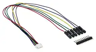


SEN5X JUMPER WIRE
Jumper Wire, 6 Pin, For Evaluation Board, SEN5x Series
- Manufacturer: SENSIRION
- Product type:
- SVHC: No SVHC (12-Jan-2017)
| Delivery and price | |
|---|---|
| Units per pack | 1 |
| Price | 8.33 € |
| Current stock | 10+ |
| Lead time | 15 days |
## **Datasheet SEN5x**
Environmental Sensor Node for HVAC and Air Quality Applications
- PM, NOx, VOC, RH & T sensor platform
- Fast & easy integration
- One driver for up to 8 data signals
- Superior sensing accuracy and lifetime
- Fully calibrated digital output
## **Overview**
The SEN5x is a unique sensor module family combining the measurement of critical air quality parameters – particulate matter, VOC, NOx, humidity, and temperature – in a single package. The modules are a result of Sensirion’s extensive experience in environmental sensing and offers best possible performance of each sensing parameter, a superior lifetime, as well as a compact form factor. The SEN5x sensors provide fully calibrated outputs with a digital interface. The combination of all measurement parameters in a single device allows manufacturers of air quality devices to reduce design and integration efforts, shorten development times and simplify their supply chain. Proprietary algorithms enable straightforward integration into HVAC and air quality applications allowing resource/time savings and focus on core competencies. The implemented Sensirion Temperature Acceleration Routine (STAR) engine accelerates the device’s response to ambient temperature change by a factor of 2-3 to provide better UX and more accurate measurements to end users.
1/30
Version 2 – D1 – March 2022
www.sensirion.com
**==> picture [447 x 252] intentionally omitted <==**
**----- Start of picture text -----**<br>
Air<br>Flow<br>RH & T<br>I2C<br>VOC & NOx<br>3V3 Power 5V<br>VDD<br>Laser Supply<br>Laser<br>Controller SDA<br>ESD<br>MCU<br>Protection<br>Amplifier & SCL<br>Filter<br>Photo-<br>diode GND<br>Fan<br>Fan<br>Controller<br>**----- End of picture text -----**<br>
**Figure 1** Functional block diagram of the SEN5x. The RH & T and VOC sensors are only contained in the SEN54 and SEN55, the NOx signal is only contained in the SEN55.
2/30
Version 2 – D1 – March 2022
www.sensirion.com
## **Content**
|1|Product Family Overview and Ordering Information|4|
|---|---|---|
|2|Environmental Sensor Node Specifications|5|
|3|Electrical Specifications|11|
|4|Hardware Interface Specifications|13|
|5|Functional Overview|14|
|6|Operation and Communication through the I2C Interface|17|
|7|Technical Drawings|26|
|8|Revision History|28|
|9|Important Notices|29|
3/30
Version 2 – D1 – March 2022
www.sensirion.com
## **1 Product Family Overview and Ordering Information**
The SEN5x product family consists of a lineup of sensors with identical dimensions, identical hardware & firmware interface, and varying number of sensor outputs. **Table 1** gives an overview of all available product variants with their respective sensor outputs.
Specifications and commands for sensor inputs/outputs only apply for the given product if the sensor output is part of this product.
|Products|Sensor outputs|Description||Article Number|
|---|---|---|---|---|
|SEN50-SDN-T|Particulate Matter|Particulate matter sensor, tray packaging,<br>45 pcs. per tray||3.000.667|
|SEN54-SDN-T|Particulate Matter<br>Relative Humidity<br>Temperature<br>VOC Index|Environmental sensor node, tray packaging,<br>45 pcs. per tray||3.000.535|
|SEN55-SDN-T|Particulate Matter|Environmental sensor node, tray packaging,||3.000.593|
||Relative Humidity|45 pcs. per tray|||
||Temperature||||
||VOC Index||||
||NOxIndex||||
**Table 1:** Sensor module specifications.
4/30
Version 2 – D1 – March 2022
www.sensirion.com
## **2 Environmental Sensor Node Specifications**
Default conditions of standard Measurement-Mode (6.1.1), 25 °C and 5 V supply voltage apply to values in the table below, unless otherwise stated.
## **2.1 Sensor Module Specifications**
|Parameter|Conditions|Value||Units|
|---|---|---|---|---|
|Samplinginterval|-|10.03||s|
|Lifetime1|24 h/dayoperation|> 10||years|
|Acoustic emission level|0.2 m|24||dB(A)|
|Longterm acoustic emission level drift|0.2 m|+0.5||dB(A)/year|
|Weight|-|36.410%||g|
**Table 2:** Sensor module specifications.
> 1 Lifetime is based on mean-time-to-failure (MTTF) calculation. Lifetime might vary depending on different operating conditions.
5/30
Version 2 – D1 – March 2022
www.sensirion.com
## **2.2 Particulate Matter Specifications**
|Parameter<br>~~a~~|Parameter<br>~~a~~|Conditions<br>~~a~~<br>~~a~~|Value<br>Units<br>~~a~~<br>~~a~~|Value<br>Units<br>~~a~~<br>~~a~~|
|---|---|---|---|---|
|Mass concentration specified range<br>-<br>0 to 1’000<br>μg/m3<br>~~a~~<br>~~a~~<br>~~a~~<br>~~a~~|||||
|Mass concentration size range<br>PM1.0<br>0.3 to 1.0<br>μm<br>PM2.5<br>0.3 to 2.5<br>μm<br>PM4<br>0.3 to 4.0<br>μm<br>PM10<br>0.3 to 10.0<br>μm<br>~~a~~<br>~~a~~<br>~~a~~<br>~~a~~<br>~~a~~<br>~~a~~<br>~~a~~<br>~~eeee~~|||||
|Mass concentration precision2,3for PM1 and PM2.540 to 100μg/m3<br>5μg/m3AND 5 % m.v.<br>100 to 1000 μg/m3<br>10<br>% m.v.<br>~~a~~<br>~~a~~<br>~~ee~~<br>~~eeee~~|||||
|Mass concentration precision2,3 for PM4, PM105<br>0 to 100 μg/m3<br>25<br>μg/m3<br>100 to 1000μg/m3<br>25<br>% m.v.<br>~~ee ee~~<br>~~ne~~<br>~~a~~|||||
|Maximum long-term mass concentration precision<br>limit drift<br>0 to 100 μg/m3<br>1.25<br>μg/m3 /year<br>100 to 1000 μg/m3<br>1.25<br>% m.v. /year<br>~~ne~~<br>~~a~~<br>~~ee~~<br>~~a~~|||||
|Typical start-up time6<br>number<br>concentration<br>200 – 3000 #/cm3<br>8<br>s<br>100 – 200 #/cm3<br>16<br>s<br>50 – 100 #/cm3<br>30<br>s<br>~~ee~~<br>~~a~~<br>~~——~~<br>~~——~~<br>~~——~~|||||
|Sensor output characteristics<br>PM2.5 mass concentration<br>Calibrated to TSI DustTrak™<br>DRX 8533 Ambient Mode<br>~~——~~<br>~~ee~~<br>~~ee~~|||||
|Additional T-dependent mass precision limit drift3<br>temperature<br>difference to 25°C<br>typ.<br>0.5<br>% m.v. / °C<br>~~ee~~<br>~~ee~~<br>~~ee~~<br>~~po~~|||||
|Laser wavelength<br>(DIN EN 60825-1 Class 1)<br>~~ee~~||typ.<br>~~ee~~<br>~~po~~|660<br>~~po~~|nm<br>~~po~~|
**Table 3:** Particulate matter sensor specifications. Default conditions of 252 °C, 5010% relative humidity and 5 V supply voltage apply unless otherwise stated. ‘max.’ means ‘maximum’, ‘typ.’ means ‘typical’, ‘% m.v.’ means ‘% of measured value’.
> 2 Also referred to as “between-parts variation” or “device-to-device variation”.
> 3 For further details, please refer to the document “Sensirion Particulate Matter Sensor Specification Statement”.
> 4 Verification Aerosol for PM2.5 is a 3% atomized KCl solution. Deviation to reference instrument is verified in end-tests for every sensor after calibration.
> 5 PM4 and PM10 output values are calculated based on distribution profile of all measured particles.
> 6 Time after starting Measurement-Mode, until a stable measurement is obtained.
6/30
Version 2 – D1 – March 2022
www.sensirion.com
**2.3 Temperature and Humidity Specifications**
|Parameter|Conditions|Value 7||Units|
|---|---|---|---|---|
|Compensated outputs8|-|Temperature and<br>Relative Humidity||°C<br>%RH|
|Typical accuracytemperature|@15-30 °C, 50 %RH|0.45||°C|
|Max. accuracytemperature|@15-30 °C,50 %RH|±0.7||°C|
|Repeatabilitytemperature|@25 °C,50 %RH|0.1||°C|
|Response time temperature9|@ 25 °C, 50 %RH,63%|< 60||s|
|Typical accuracyrelative humidity|@25 °C, 30-70 %RH|4.5||%RH|
|Max. accuracyrelative humidity|@25 °C,30-70 %RH|±6||%RH|
|Repeatabilityrelative humidity|@25 °C, 50 %RH|1||%RH|
|Response time relative humidity10|@25 °C,50 %RH, 63%|< 20||s|
**Table 4:** Temperature and humidity specifications.
> 7 For the definition of the typical and max. accuracy tolerance, please refer to the document “Sensirion Humidity Sensor Specification Statement”.
> 8 Self-heating of the module is compensated according to the application note “Temperature Acceleration and Compensation Instructions for SEN5x”.
> 9 For a step from 15°C to 25°C
> 10 For a step from 75%RH to 25%RH
7/30
Version 2 – D1 – March 2022
www.sensirion.com
**2.4 Gas Specifications**
|Parameter<br>Comments<br>~~a~~<br>~~ee~~<br>~~eee~~|Min.<br>~~po~~<br>~~eee~~|Units<br>Typ.11<br>Max.<br>~~po~~<br>~~eee~~|Units<br>Typ.11<br>Max.<br>~~po~~<br>~~eee~~|Units<br>Typ.11<br>Max.<br>~~po~~<br>~~eee~~|
|---|---|---|---|---|
|Output signals<br>VOC Index<br>1<br>–<br>500<br>VOC Indexpoints<br>NOxIndex<br>1<br>–<br>500<br>NOx Indexpoints<br>~~po~~<br>~~a~~<br>~~ee~~<br>~~eee~~|||||
|Device-to-device<br>variation<br>VOC Index12<br>–<br><±15<br><±15<br>–<br>VOC Index points<br>or<br>% VOC Index m.v.<br>(the larger)<br>NOxIndex12<br>–<br><±50<br><±50<br>–<br>NOx Index points<br>or<br>% NOx Index m.v.<br>(the larger)<br>~~ee~~<br>~~eee~~<br>~~EE~~|||||
|Repeatability<br>VOC Index12<br>–<br><±5<br><±5<br>–<br>VOC Index points<br>or<br>% VOC Index m.v.<br>(the larger)<br>NOxIndex12<br>–<br><±10<br><±10<br>–<br>NOx Index points<br>or<br>% NOx Index m.v.<br>(the larger)<br>~~eSee~~<br>~~ee~~|||||
|Response time<br>Changing concentration<br>from 5 to 10 ppm of ethanol, at<br>samplinginterval of 1 s<br>63<br>–<br><10<br>–<br>s<br>90<br>–<br><30<br>–<br>s<br>~~eSee~~<br>~~ee~~<br>~~pf~~<br>~~|~~<br>~~**|**~~|||||
|Switch-on behavior<br>Time until reliablydetectingevents13<br>–<br><60<br>–<br>s<br>Time until specifications in this table<br>are met<br>VOC Index<br><1<br>–<br>h<br>NOx Index<br><6<br>–<br>h<br>~~eS ee~~<br>~~ee~~<br>~~pf~~<br>~~|~~<br>~~**|**~~<br>~~ee~~<br>~~a~~<br>~~a~~<br>~~ee~~|||||
||NOx Index<br>~~a~~<br>~~a~~|<6<br>~~a~~<br>~~ee~~|–<br>~~a~~|h<br>~~a~~|
> 11 95 % of the sensors will be within the typical tolerance corresponding to 2σ assuming a normal distribution for ≥100 sensors.
> 12 Evaluated using the calibration and test sequence according to the application note _SGP40 – Testing Guide_ . 13 Signal change during 60-s event of 5000 to 10000 ppb of ethanol or of 100 to 300 ppb of NO2 is three times larger than raw signals drift, without this event during the same duration.
8/30
Version 2 – D1 – March 2022
www.sensirion.com
## **2.5 Recommended and Absolute Maximum/Minimum Operating and Storage Conditions**
The SEN5x contains different sensing components with different recommended operating and storage ranges. To ensure an optimal performance of the SEN5x, the “SEN5x Handling Instructions” as well as the “SEN5x Mechanical Assembly and Design-in Guidelines” need to be followed.
## **2.5.1 SEN54 and SEN55**
Table 6 and Figure 2 show the recommended operating and storage conditions in which all the sensing components of the SEN54 and SEN55 show best performance, as well as absolute maximum/minimum conditions which must not be exceeded. Gas sensing specifications are guaranteed only when the SEN54 and SEN55 are operated and stored under the recommended conditions given in Table 6.
Exposure to conditions outside the recommended range may temporarily reduce sensor performance (reversible RH drift, reduced RH, T, gas, PM accuracy). Exposure to conditions outside absolute maximum/minimum range may lead to permanently reduced sensor performance (gas sensitivity drift) or cause permanent damage to the device.
The sensor must not be exposed towards condensing conditions at any time.
|Condition<br>Parameter|Condition<br>Parameter|Recommended|Recommended|Absolute Maximum/Minimum<br>Unit|Absolute Maximum/Minimum<br>Unit|Absolute Maximum/Minimum<br>Unit|
|---|---|---|---|---|---|---|
|||Min.|Max.|Min.|Max.||
|Operating conditions<br>Temperature<br>10<br>40<br>-10<br>50<br>°C<br>Relative humidity<br>20<br>80<br>0<br>90 (non-condensing) % RH|||||||
|Storage conditions<br>Temperature<br>10<br>30<br>-40<br>70<br>°C<br>Relative Humidity<br>20<br>60<br>0<br>80 (non-condensing) % RH|||||||
||Relative Humidity|20|60|0|80 (non-condensing) % RH|80 (non-condensing) % RH|
**Table 6** Recommended and absolute maximum/minimum operating and storage conditions for SEN54 and SEN55.
**==> picture [416 x 191] intentionally omitted <==**
**----- Start of picture text -----**<br>
Operating Storage<br>100 100<br>80 80<br>ioe PEREEEE<br>60 Soeleeen 60 et<br>40 40<br>200 foPELLey 200 asEEEanne-EEE<br>-40 -20 0 20 40 60 80 -40 -20 0 20 40 60 80<br>Temperature / °C Temperature / °C<br>Lou! Recommended range CJ Absolute maximum/minimum range<br>Relative humidity / % Relative humidity / %<br>**----- End of picture text -----**<br>
**Figure 2** Recommended and absolute maximum/minimum operating and storage conditions for SEN54 and SEN55.
9/30
Version 2 – D1 – March 2022
www.sensirion.com
## **2.5.2 SEN50**
**Table 7** and **Figure 3** show the recommended operating and storage conditions in which all the sensing components of the SEN50 shows the best performance, as well as absolute maximum/minimum conditions which must not be exceeded.
Exposure to conditions outside the recommended range may temporarily reduce sensor performance (PM accuracy). Exposure to conditions outside absolute maximum/minimum range may lead to permanently reduced sensor performance (gas sensitivity drift) or cause permanent damage to the device.
The sensor must not be exposed towards condensing conditions at any time.
|Condition<br>Parameter|Condition<br>Parameter|Recommended|Recommended|Absolute Maximum/Minimum<br>Unit|Absolute Maximum/Minimum<br>Unit|Absolute Maximum/Minimum<br>Unit|
|---|---|---|---|---|---|---|
|||Min.|Max.|Min.|Max.||
|Operating conditions<br>Temperature<br>10<br>40<br>-10<br>60<br>°C<br>Relative humidity<br>20<br>80<br>0<br>95 (non-condensing) % RH|||||||
|Storage conditions<br>Temperature<br>10<br>30<br>-40<br>70<br>°C<br>Relative Humidity<br>20<br>60<br>0<br>95 (non-condensing) % RH|||||||
||Relative Humidity|20|60|0|95 (non-condensing) % RH|95 (non-condensing) % RH|
**Table 7** Recommended and absolute maximum/minimum operating and storage conditions for SEN50.
**==> picture [416 x 191] intentionally omitted <==**
**----- Start of picture text -----**<br>
Operating Storage<br>100 100<br>80 80<br>60 60<br>40 40<br>20 20<br>0 0<br>-40 -20 0 20 40 60 80 -40 -20 0 20 40 60 80<br>Temperature / ° C Temperature / ° C<br>Recommended range Absolute maximum/minimum range<br>Relative humidity / % Relative humidity / %<br>**----- End of picture text -----**<br>
**Figure 3** Recommended and absolute maximum/minimum operating and storage conditions for SEN50.
10/30
Version 2 – D1 – March 2022
www.sensirion.com
## **3 Electrical Specifications**
## **3.1 Electrical Characteristics**
|Parameter<br>Conditions<br>Min<br>Typ<br>Max<br>Unit<br>Supplyvoltage<br>-<br>4.5<br>5.0<br>5.5<br>V<br>~~OO~~|
|---|
|Sensor startup time (Time after<br>power-on until I2C<br>communication can be started)<br>-<br>-<br>-<br>50<br>ms<br>Average supply current<br>Idle Mode (first 10 seconds)<br>SEN55<br>-<br>3.8<br>4.2<br>mA<br>SEN54<br>-<br>0.7<br>1<br>SEN50<br>-<br>0.7<br>1<br>Idle Mode (after first 10 seconds)<br>SEN55<br>-<br>2.6<br>3<br>SEN54<br>-<br>0.7<br>1<br>SEN50<br>-<br>0.7<br>1<br>RHT/Gas-only Measurement Mode<br>SEN55<br>-<br>6.8<br>8<br>SEN54<br>-<br>6.5<br>7.7<br>Measurement-Mode (first 60 seconds)<br>SEN55<br>-<br>70<br>100<br>SEN54<br>-<br>70<br>100<br>SEN50<br>-<br>70<br>100<br>Measurement-Mode (after first 60<br>seconds)<br>SEN55<br>-<br>63<br>80<br>SEN54<br>-<br>63<br>80<br>SEN50<br>-<br>63<br>80<br>Peak supplycurrent<br>Measurement mode(pulse width of 16µs)<br>-<br>100<br>110<br>mA<br>Input high level voltage(VIH)<br>-<br>2.31<br>-<br>5.5<br>V<br>Input low level voltage(VIL)<br>-<br>0<br>-<br>0.99<br>~~a ee~~<br>~~es~~<br>~~ee ee ee~~<br>~~a~~<br>~~ee ee ee~~<br>~~a ee~~<br>~~ee~~~~**e**~~<br>~~ee~~<br>~~ee e~~<br>~~ee~~<br>~~ee~~<br>~~ee~~<br>~~ee ee ee~~<br>~~a~~<br>~~eee~~<br>~~es~~<br>~~ee ee ee~~<br>~~ee ee ee eee~~<br>~~a ee~~<br>~~ee~~<br>~~es~~<br>~~ee ee ee~~<br>~~po~~<br>~~ee ee eee eee~~<br>~~a ee~~<br>~~eee~~<br>~~aee~~<br>~~a~~|
|Output low level voltage(VOL)<br>Sink current <6mA<br>0<br>0<br>0.4<br>~~pf~~|
**Table 8** Electrical specifications at 25°C.
## **3.2 Absolute Maximum Ratings**
Stress levels beyond those listed in Table 9 may cause permanent damage to the device. These are stress ratings only and functional operation of the device at these conditions cannot be guaranteed. Exposure to the absolute maximum rating conditions for extended periods may affect the reliability of the device.
|Parameter|Min|Max||Unit|
|---|---|---|---|---|
|Supplyvoltage VDD|-0.3|5.5|||
|Interface Select SEL|-0.3|5.5||V|
|I/Opins(RX/SDA,TX/SCL)|-0.3|5.5|||
|Max. current on anyI/Opin|-16|16||mA|
|Operatingtemperature range||see Table 6|||
|Operatinghumidityrange||see Table 6|||
|Storage temperature range(short-term,e.g. transport)||see Table 6|||
|Storage humidityrange(short-term,e.g. transport)||see Table 6|||
**Table 9:** Absolute minimum and maximum ratings.
11/30
Version 2 – D1 – March 2022
www.sensirion.com
## **3.3 ESD / EMC Ratings**
## **Immunity**
|Description|Standard||Rating|
|---|---|---|---|
|Electro Static Discharge|IEC 61000-4-2||±4 kV contact,±8 kV air|
|Power-FrequencyMagnetic Field|IEC 61000-4-8||30A/m,50Hz and 60Hz|
|Radio-FrequencyEM-Field AM-modulated|IEC 61000-4-3||80MHz - 1000MHz,3V/m,80% AM@1kHz|
|Radio-FrequencyEM-Field AM-modulated|IEC 61000-4-3||1.4GHz – 6GHz,3V/m,80% AM@1kHz|
## **Emission**
|Description|Standard||Rating|
|---|---|---|---|
|Emission in SAC for 30MHz to 230MHz|IEC/CISPR 16||40dB(µV/m)QP@3m|
|Emission in SAC for 230MHz to 1000MHz|IEC/CISPR 16||47dB(µV/m)QP@3m|
12/30
Version 2 – D1 – March 2022
www.sensirion.com
## **4 Hardware Interface Specifications**
The sensor is equipped with a serial communication interface. The interface connector is located at the side of the sensor adjacent to the air outlet. The used connector is ACES 51451-0060N-001 on the sensor’s side, while the corresponding plug is ACES 51452-006H0H0-001. At the time of writing JST GHR-06V-S is compatible and can be used as well. In **Table 11** , a description of the pin layout is given.
|Part<br>Connector|Part<br>Connector|
|---|---|
|Sensor<br>side<br>ACES 51451-0060N-001||
|Cable side|Compatible with ACES 51452-006H0H0-001 (e.g.,<br>JST GHR-06V-S)|
**Table 10:** SEN5x connector
|Pin|Name|Description<br>Comments|Description<br>Comments|
|---|---|---|---|
|1<br>VDD<br>Supplyvoltage<br>5V ± 10%||||
|2<br>GND<br>Ground||||
|3<br>SDA<br>Serial data input / output<br>LVTTL 3.3V<br>compatible||||
|4<br>SCL<br>Serial clock input<br>LVTTL 3.3V<br>compatible||||
|5<br>SEL<br>Interface select<br>Connect to<br>GND||||
|6|NC|Do not connect||
**Figure 4** Pin layout. The communication interface connector (ACES 51451-0060N-001) is located at the side of the sensor adjacent to the air outlet.
**Table 11:** SEN5x pin assignment.
Note, that there is an internal electrical connection between GND pin (2) and metal shielding. Keep this metal shielding electrically floating to avoid any unintended currents through this internal connection. If this is not an option, proper external potential equalization between GND pin and any potential connected to the shielding is mandatory. Any current though the connection between GND and metal shielding may damage the product and poses a safety risk through overheating.
13/30
Version 2 – D1 – March 2022
www.sensirion.com
## **5 Functional Overview**
## **5.1 Operating Modes**
**==> picture [142 x 32] intentionally omitted <==**
**----- Start of picture text -----**<br>
Start<br>Start<br>RHT/Gas-Only<br>Measurement<br>Measurement<br>**----- End of picture text -----**<br>
**Figure 5** SEN5x operating modes. The RHT/Gas-Only Measurement Mode is applicable for SEN55 and SEN54 only. The direct switch between Measurement and RHT/Gas-Only Measurement mode is available only for firmware version v2 and newer.
## **Idle**
- The module is in Idle Mode after power on or reset.
- Most of the internal electronics switched off /reduced power consumption.
- Fan and laser are switched off.
- The module is ready to receive and process any command.
## **Measurement**
- All electronics switched on / max. power consumption.
- The measurement is running, and the module is continuously processing measurement data.
- New readings are available every second.
## **RHT/Gas-Only Measurement**
- The RHT/Gas-Only Measurement mode can be entered from Idle and the Measurement modes. The direct switch between Measurement and RHT/Gas-Only Measurement mode is available only for firmware version v2 and newer.
- Fan and laser are switched off for reduced power consumption.
- RHT and gas sensor are switched on. RHT and gas measurement is running, and the module is continuously processing measurement data.
- New readings are available every second.
- The PM output is 0xFFFF
14/30
Version 2 – D1 – March 2022
www.sensirion.com
## **5.2 Fan Auto Cleaning**
When the module is in Measurement-Mode an automatic fan-cleaning procedure will be triggered periodically following a defined cleaning interval. This will accelerate the fan to maximum speed for 10 seconds to blow out the accumulated dust inside the fan.
- Measurement values are not updated while the fan-cleaning is running.
- The cleaning interval is set to 604’800 seconds (i.e., 168 hours or 1 week) with a tolerance of 3%.
- The interval can be configured using the Set Automatic Cleaning Interval command.
- Set the interval to 0 to disable the automatic cleaning.
- A sensor reset, resets the cleaning interval to its default value
- If the sensor is switched off, the time counter is reset to 0. Make sure to trigger a cleaning cycle at least every week if the sensor is switched off and on periodically (e.g., once per day).
- The cleaning procedure can also be started manually with the Start Cleaning command.
## **5.3 Temperature compensation**
By default, the temperature and humidity outputs from the sensor are compensated for the modules self-heating. If the module is designed into a device, the temperature compensation might need to be adapted to incorporate the change in thermal coupling and self-heating of other device components.
A guide to achieve optimal performance, including references to mechanical design-in examples can be found in the app note “Temperature Acceleration and Compensation Instructions for SEN5x” at www.sensirion.com.
## **5.4 Device Status Register**
The Device Status Register is a 32-bit register that contains information about the internal state of the module.
|31|30|29|28|27|26|25|24|23|22|21|20|19|18|17|16|
|---|---|---|---|---|---|---|---|---|---|---|---|---|---|---|---|
|||||||||||Warning||Info||||
|res.|res.|res.|res.|res.|res.|res.|res.|res.|res.|SPEED|res.|FAN|res.|res.|res.|
|15|14|13|12|11|10|9|8|7|6|5|4|3|2|1|0|
|||||||||Error|Error|Error|Error|||||
||res.|res.|res.|res.|res.|res.|res.|GAS<br>SENSOR|RHT|LASER|FAN|res.|res.|res.|res.|
Note: All “res.” bits are reserved for internal use or future versions. These bits can be both 0 and 1 and should therefore be ignored.
Bit 21 **SPEED:** Fan speed out of range
- 0: Fan speed is ok.
- 1: Fan speed is too high or too low.
- During the first 3 seconds after starting the measurement (fan start-up) the fan speed is not checked.
- The fan speed is also not checked during the auto cleaning procedure.
- Apart from the two exceptions mentioned above, the fan speed is checked once per second in the measurement mode. If it is out of range twice in succession, the SPEED-bit is set.
- At very high or low ambient temperatures, the fan may take longer to reach its target speed after start-up. In this case, the bit will be set. As soon as the target speed is reached, this bit is cleared automatically.
- If this bit is constantly set, this indicates a problem with the power supply or that the fan is no longer working properly
15/30
Version 2 – D1 – March 2022
www.sensirion.com
## Bit 19 **FAN:** Fan cleaning active
- 0: Fan is running normal.
- 1: Active during the automatic cleaning procedure of the fan
## Bit 7 **GAS SENSOR:** Gas sensor error (VOC & NOx)
- 0: Gas sensor is running normal.
- 1: Gas sensor error
## Bit 6 **RHT:** RHT communication error
- 0: RHT sensor is running normal.
- 1: Error in internal communication with the RHT sensor
## Bit 5 **LASER:** Laser failure
- 0: Laser current is ok.
- 1: Laser is switched on and current is out of range.
- The laser current is checked once per second in the measurement mode. If it is out of range, the LASER-bit is set.
- If the laser current is back within limits, this bit will be not cleared automatically.
- A laser failure can occur at very high temperatures outside of specifications or when the laser module is defective.
## Bit 4 **FAN:** Fan failure, fan is mechanically blocked or broken.
- 0: Fan works as expected.
- 1: Fan is switched on, but the measured fan speed is 0 RPM.
- The fan is checked once per second in the measurement mode. If 0 RPM is measured twice in succession, the FAN bit is set.
- The FAN-bit will not be cleared automatically.
- A fan failure can occur if the fan is mechanically blocked or broken.
16/30
Version 2 – D1 – March 2022
www.sensirion.com
## **6 Operation and Communication through the I[2] C Interface**
Usage:
I[2] C address: 0x69 Max. speed: standard mode, 100 kbit/s Clock stretching: not used
Both SCL and SDA lines are open drain I/Os. They should be connected to external pull-up resistors (e.g. Rp = 10 kΩ). **Important notice:** in order to correctly select I[2] C as interface, the interface select (SEL) pin must be pulled to GND before or at the same time the sensor is powered up.
**Figure 6** : Typical I[2] C application circuit.
To avoid electromagnetic interference and crosstalk, use as short as possible electronic connections (< 10 cm) and/or well shielded connection cables.
For detailed information on the I2C protocol, refer to NXP I2C-bus specification[14] .
## **Checksum Calculation**
The Read and Write Commands transmit the data in 2-byte packets, followed by an 8-bit checksum. The checksum is calculated as follows:
|Property<br>Name||Value<br>CRC-8||uint8_t CalcCrc(uint8_t data[2]) {<br>uint8_t crc = 0xFF;<br>for(int i = 0; i < 2; i++) {|
|---|---|---|---|---|
|Protected Data||read and/or write data||crc ^= data[i];|
|Width<br>Polynomial<br>Initialization||8 bit<br>0x31(x^8 + x^5 + x^4 + 1)<br>0xFF||for(uint8_t bit = 8; bit > 0; --bit) {<br>if(crc & 0x80) {<br>crc = (crc << 1) ^ 0x31u;<br>} else {<br>crc = (crc << 1);|
|Reflect Input||false||}<br>}|
|Reflect Output||false||}|
|Final XOR||0x00||return crc;<br>}|
|Example||CRC(0xBEEF)= 0x92|||
_Please note that the checksums are used only for the 2-byte data packets. The command code itself already contains a 3-bit CRC and therefore no checksum must be appended to it._
> 14 http://www.nxp.com/documents/user_manual/UM10204.pdf
17/30
Version 2 – D1 – March 2022
www.sensirion.com
## **6.1 I[2] C Commands**
The following table shows an overview of the available I[2] C commands.
|Address<br>Pointer<br>~~ee~~<br>~~a~~|Command Name<br>~~ee~~|Communication<br>Command execution time<br>~~ee~~<br>~~ee~~|Communication<br>Command execution time<br>~~ee~~<br>~~ee~~|
|---|---|---|---|
|0x0021<br>Start Measurement<br>Write Data<br>< 50 ms<br>~~ee~~<br>~~ee~~<br>~~a~~||||
|0x0037<br>Start Measurement in<br>RHT/Gas-OnlyMeasurement Mode<br>Write Data<br>< 50 ms<br>~~ee~~<br>~~a~~<br>~~a~~||||
|0x0104<br>StopMeasurement<br>Write Data<br>< 200 ms<br>~~a~~<br>~~a~~||||
|0x0202<br>Read Data-ReadyFlag<br>Read/ Write Data<br>< 20 ms<br>~~a~~<br>~~a~~<br>~~a~~||||
|0x03C4<br>Read Measured Values<br>Read/ Write Data<br>< 20 ms<br>~~a~~<br>~~a~~<br>~~a~~<br>~~ee~~<br>~~a~~||||
|0x60B2<br>Read/ Write Temperature<br>Compensation Parameters<br>Read/ Write Data and Parameters<br>< 20 ms<br>~~a~~<br>~~aee~~<br>~~a~~||||
|0x60C6<br>Read/ Write Warm Start<br>Parameters<br>Read/ Write Data and Parameters<br>< 20 ms<br>~~a ee~~<br>~~a~~||||
|0x60D0<br>Read/Write VOC Algorithm Tuning<br>Parameters<br>Read/ Write Data and Parameters<br>< 20 ms<br> ~~ee~~<br>~~a~~<br>~~a~~<br>~~ee~~<br>~~a~~||||
|0x60E1<br>Read/Write NOx Algorithm Tuning<br>Parameters<br>Read/ Write Data and Parameters<br>< 20 ms<br>~~a~~<br>~~a~~<br>~~ee~~<br>~~aeeee~~<br>~~a~~||||
|0x60F7<br>Read/Write RH/T Acceleration<br>Mode<br>Read/ Write Data and Parameters<br>< 20 ms<br>~~ee~~<br>~~aeeee~~<br>~~a~~||||
|0x6181<br>Read/Write VOC Algorithm State<br>Read/ Write Data and Parameters<br>< 20 ms<br>~~ee~~<br>~~a eeee~~<br>~~a~~||||
|0x5607<br>Start Fan Cleaning<br>Write Data<br>< 20 ms<br>~~a~~||||
|0x8004<br>Read/Write Auto CleaningInterval<br>Read/ Write Data and Parameters<br>< 20 ms<br>~~a~~||||
|0xD014<br>Read Product Name<br>Read/ Write Data<br>< 20 ms<br>~~a~~<br>~~a~~||||
|0xD033<br>Read Serial Number<br>Read/ Write Data<br>< 20 ms<br>~~a~~<br>~~aa~~||||
|0xD100<br>Read Firmware Version<br>Read/ Write Data<br>< 20 ms<br>~~aa~~<br>~~a~~<br>~~a~~||||
|0xD206<br>Read Device Status<br>Read/ Write Data<br>< 20 ms<br>~~a~~<br>~~a~~<br>~~>~~||||
|0xD210<br>Clear Device Status<br>Write Data<br>< 20 ms<br>~~>~~<br>~~a~~<br>~~a~~||||
|0xD304<br>~~a~~|Reset|Write Data|< 100 ms|
**Table 12:** Reference table for I[2] C commands.
Please note that all commands are volatile.
## **6.1.1 Start Measurement (0x0021)**
Starts the measurement. After power up, the module is in Idle-Mode. Before any measurement values can be read, the Measurement-Mode needs to be started using this command.
## **6.1.2 Start Measurement in RHT/Gas-Only Measurement Mode (0x0037)**
Starts a continuous measurement without PM. Only humidity, temperature, VOC, and NOx are available in this mode. Laser and fan are switched off to keep power consumption low.
## **6.1.3 Stop Measurement (0x0104)**
Stops the measurement. Use this command to return to the initial state (Idle-Mode).
## **6.1.4 Read Data-Ready Flag (0x0202)**
This command can be used for polling to find out when new measurements are available.
18/30
Version 2 – D1 – March 2022
www.sensirion.com
## **Read/Write Data:**
|Byte #||Description|
|---|---|---|
|0||unused,always 0x00|
|1||**Data-Ready Flag**<br>0x00: no new measurements available<br>0x01: new measurements readyto read|
|2||Checksum for bytes 0,1|
## **6.1.5 Read Measured Values (0x03C4)**
Reads the measured values from the sensor module and resets the “Data-Ready Flag”. If the sensor module is in Measurement-Mode, an updated measurement value is provided every second and the “Data-Ready Flag” is set. If no synchronized readout is desired, the “Data-Ready Flag” can be ignored. The command “Read Measured Values” always returns the latest measured values. After sending the “Read Measured Values” command, a wait time of 10 ms is needed so that the sensor internally can fill the data buffers. After 20 ms, the read data header can be sent to read out the sensor data. In RHT/Gas-Only Measurement Mode, the PM output is 0xFFFF. If any value is unknown, 0xFFFF is returned.
|Byte #<br>~~sO~~|Datatype<br>~~sO~~|Scale factor<br>Description<br>~~sO~~|Scale factor<br>Description<br>~~sO~~|
|---|---|---|---|
|0..1<br>big-endian, uint16<br>10<br>Mass Concentration PM1.0 [µg/m³]<br>~~sO~~<br>~~a~~<br>~~Ge~~||||
|2<br>Checksum for bytes 0, 1<br>~~a~~<br>~~Ge~~<br>~~a CG~~<br>~~es~~||||
|3..4<br>big-endian, uint16<br>10<br>Mass Concentration PM2.5 [µg/m³]<br>~~a CG~~<br>~~es~~<br>~~eeeG~~||||
|5<br>Checksum for bytes 3, 4<br>~~es~~<br>~~eeeG~~||||
|6..7<br>big-endian, uint16<br>10<br>Mass Concentration PM4.0 [µg/m³]<br>~~eeeG~~<br>~~aCG~~||||
|8<br>Checksum for bytes 6, 7<br>~~a CG~~<br>~~aDG~~<br>~~aa~~<br>~~GO~~||||
|9..10<br>big-endian, uint16<br>10<br>Mass Concentration PM10 [µg/m³]<br>~~a DG~~<br>~~aa~~<br>~~GO~~||||
|11<br>Checksum for bytes 9, 10<br>~~a a~~<br>~~GO~~<br>~~a CG~~||||
|12..13<br>big-endian, int16<br>100<br>Compensated Ambient Humidity [%RH]<br>~~a CG~~<br>~~a~~||||
|14<br>Checksum for bytes 12, 13<br>~~Ge~~||||
|15..16<br>big-endian, int16<br>200<br>Compensated Ambient Temperature [°C]<br>~~Ge~~<br>~~a CG~~||||
|17<br>Checksum for bytes 15, 16<br>~~a CG~~<br>~~a~~<br>~~eG~~<br>~~es~~||||
|18..19<br>big-endian, int16<br>10<br>VOC Index<br>~~a~~<br>~~eG~~<br>~~es~~<br>~~es~~||||
|20<br>Checksum for bytes 18, 19<br>~~es~~<br>~~es~~<br>~~ee~~||||
|21..22<br>big-endian, int16<br>10<br>NOx Index<br>~~es~~<br>~~ee~~<br>~~Ge~~||||
|23<br>~~eea~~|Checksum for bytes 21, 22<br>~~a~~|~~a~~<br>~~Ge~~|~~a~~|
19/30
Version 2 – D1 – March 2022
www.sensirion.com
## **6.1.6 Read/ Write Temperature Compensation Parameters (0x60B2)**
These commands allow to compensate temperature effects of the design-in at customer side by applying a custom temperature offset to the ambient temperature. The compensated ambient temperature is calculated as follows:
T_Ambient_Compensated = T_Ambient + (slope*T_Ambient) + offset
Where slope and offset are the values set with this command, smoothed with the specified time constant. The time constant is how fast the slope and offset are applied. After the specified value in seconds, 63% of the new slope and offset are applied.
More details about the tuning of these parameters are included in the application note “Temperature Acceleration and Compensation Instructions for SEN5x”.
All temperatures (T_Ambient_Compensated,T_Ambient and offset) are represented in °C.
**Read/Write Data and Parameters:**
|Byte #|Datatype|Scale factor<br>Description|Scale factor<br>Description|
|---|---|---|---|
|0..1<br>big-endian, int16<br>200<br>Temperature offset [°C] (default value: 0)||||
|2<br>Checksum for bytes 0, 1||||
|3..4<br>big-endian, int16<br>10000<br>Normalized temperature offset slope (default value: 0)||||
|5<br>Checksum for bytes 3, 4||||
|6..7<br>big-endian, uint16<br>1<br>Time constant in seconds (default value: 0)||||
|8|Checksum for bytes 6, 7|||
## **6.1.7 Read/ Write Warm Start Parameter (0x60C6)**
The temperature compensation algorithm is optimized for a cold start by default, i.e., it is assumed that the "Start Measurement" commands are called on a device not yet warmed up by previous measurements. If the measurement is started on a device that is already warmed up, this parameter can be used to improve the initial accuracy of the ambient temperature output. This parameter can be gotten and set in any state of the device, but it is applied only the next time starting a measurement, i.e., when sending a "Start Measurement" command. So, the parameter needs to be written before a warm-start measurement is started.
**Read/Write Data and Parameters:**
|Byte #|Datatype|Scale factor<br>Description|Scale factor<br>Description|
|---|---|---|---|
|0..1<br>big-endian, uint16<br>1<br>Warm start behavior as a value in the range from<br>0 (cold start, default value) to 65535 (warm start).<br>(default value: 0)||||
|2|Checksum for bytes 0, 1|||
20/30
Version 2 – D1 – March 2022
www.sensirion.com
## **6.1.8 Read/ Write VOC Algorithm Tuning Parameters (0x60D0)**
The VOC algorithm can be customized by tuning 6 different parameters. More details on the tuning instructions are provided in the application note “Engineering Guidelines for SEN5x”. Note that this command is available only in idle mode. In measure mode, this command has no effect. In addition, it has no effect if at least one parameter is outside the specified range.
**Read/Write Data and Parameters:**
|Byte #<br>~~re~~|Datatype<br>~~re~~|Scale<br>factor<br>Description<br>~~re~~|Scale<br>factor<br>Description<br>~~re~~|
|---|---|---|---|
|0..1<br>big-endian, int16<br>1<br>Index Offset<br>VOC index representing typical (average) conditions. Allowed<br>values are in range 1..250. The default value is 100.<br>~~re~~<br>~~ee~~||||
|2<br>Checksum for bytes 0, 1<br>~~a~~<br>~~pf}~~||||
|3..4<br>big-endian, int16<br>1<br>Learning Time Offset Hours<br>Time constant to estimate the VOC algorithm offset from the<br>history in hours. Past events will be forgotten after about twice the<br>learning time. Allowed values are in range 1..1000. The default<br>value is 12 hours.<br>~~a~~<br>~~pf}~~||||
|5<br>Checksum for bytes 3, 4<br>~~pf}~~<br>~~a~~<br>~~P|~~||||
|6..7<br>big-endian, int16<br>1<br>Learning Time Gain Hours<br>Time constant to estimate the VOC algorithm gain from the history<br>in hours. Past events will be forgotten after about twice the<br>learning time. Allowed values are in range 1..1000. The default<br>value is 12 hours.<br>~~pf}~~<br>~~a~~<br>~~P|~~||||
|8<br>Checksum for bytes 6, 7<br>~~P|~~<br>~~aa~~||||
|9..10<br>big-endian, int16<br>1<br>Gating Max Duration Minutes<br>Maximum duration of gating in minutes (freeze of estimator during<br>high VOC index signal). Zero disables the gating. Allowed values<br>are in range 0..3000. The default value is 180 minutes.<br>~~P|~~<br>~~a a~~<br>~~ee~~||||
|11<br>Checksum for bytes 9, 10<br>~~ee~~<br>~~a~~<br>~~ef}~~||||
|12..13<br>big-endian, int16<br>1<br>Std Initial<br>Initial estimate for standard deviation. Lower value boosts events<br>during initial learning period, but may result in larger device-to-<br>device variations. Allowed values are in range 10..5000. The<br>default value is 50.<br>~~a~~<br>~~ef}~~||||
|14<br>Checksum for bytes 12, 13<br>~~ef}~~<br>~~aa~~||||
|15..16<br>big-endian, int16<br>1<br>Gain Factor<br>Gain factor to amplify or to attenuate the VOC index output.<br>Allowed values are in range 1..1000. The default value is 230.<br>~~ef}~~<br>~~a a~~<br>~~re~~||||
|17<br>~~a~~|Checksum for bytes 15, 16|||
21/30
Version 2 – D1 – March 2022
www.sensirion.com
## **6.1.9 Read/ Write NOx Algorithm Tuning Parameters (0x60E1)**
The NOx algorithm can be customized by tuning 6 different parameters. More details on the tuning instructions are provided in the application note “Engineering Guidelines for SEN5x”. This command is available only in idle mode. In measure mode, this command has no effect. In addition, it has no effect if at least one parameter is outside the specified range.
**Read/Write Data and Parameters:**
|Byte #<br>~~ee~~|Datatype<br>~~ee~~|Scale factor<br>Description<br>~~ee~~|Scale factor<br>Description<br>~~ee~~|
|---|---|---|---|
|0..1<br>big-endian, int16<br>1<br>Index Offset<br>NOx index representing typical (average) conditions. Allowed<br>values are in range 1..250. The default value is 1.<br>~~ee~~<br>~~ee~~||||
|2<br>Checksum for bytes 0, 1<br>~~ee~~<br>~~ee~~<br>~~ef~~||||
|3..4<br>big-endian, int16<br>1<br>Learning Time Offset Hours<br>Time constant to estimate the NOx algorithm offset from the<br>history in hours. Past events will be forgotten after about twice the<br>learning time. Allowed values are in range 1..1000. The default<br>value is 12 hours.<br>~~efff~~||||
|5<br>Checksum for bytes 3, 4<br>~~efff~~<br>~~ef~~||||
|6..7<br>big-endian, int16<br>1<br>Learning Time Gain Hours<br>The time constant to estimate the NOx algorithm gain from the<br>history has no impact for NOx. This parameter is still in place for<br>consistency reasons with the VOC tuning parameters command.<br>Thisparameter must always be set to 12 hours.<br>~~ef~~<br>~~efff~~||||
|8<br>Checksum for bytes 6, 7<br>~~efff~~||||
|9..10<br>big-endian, int16<br>1<br>Gating Max Duration Minutes<br>Maximum duration of gating in minutes (freeze of estimator during<br>high NOx index signal). Set to zero to disable the gating. Allowed<br>values are in range 0..3000. The default value is 720 minutes.<br>~~ef~~<br>~~a~~||||
|11<br>Checksum for bytes 9, 10<br>~~a~~<br>~~pf~~||||
|12..13<br>big-endian, int16<br>1<br>Std Initial<br>The initial estimate for standard deviation parameter has no<br>impact for NOx. This parameter is still in place for consistency<br>reasons with the VOC tuning parameters command. This<br>parameter must always be set to 50.<br>~~pfpp~~||||
|14<br>Checksum for bytes 12,<br>13<br>~~pfpp~~||||
|15..16<br>big-endian, int16<br>1<br>Gain Factor<br>Gain factor to amplify or to attenuate the NOx index output.<br>Allowed values are in range 1..1000. The default value is 230.<br>~~a~~||||
|17<br>~~a~~<br>~~a~~|Checksum for bytes 15,<br>16|||
22/30
Version 2 – D1 – March 2022
www.sensirion.com
## **6.1.10 Read/ Write RH/T Acceleration Mode (0x60F7)**
By default, the RH/T acceleration algorithm is optimized for a sensor which is positioned in free air. If the sensor is integrated into another device, the ambient RH/T output values might not be optimal due to different thermal behavior. This parameter can be used to adapt the RH/T acceleration behavior for the actual use-case, leading in an improvement of the ambient RH/T output accuracy. There is a limited set of different modes available, each identified by a number:
- 0: Low Acceleration
- 1: High Acceleration • 2: Medium Acceleration
Medium and high accelerations are particularly indicated for air quality monitors which are subjected to large temperature changes. Low acceleration is advised for stationary devices not subject to large variations in temperature. This parameter can be changed in any state of the device, but it is applied only the next time starting a measurement, i.e., when sending a "Start Measurement" command. So, the parameter needs to be set before a new measurement is started.
**Read/Write Data and Parameters:**
|Byte #||Datatype||Scale factor||Description|
|---|---|---|---|---|---|---|
|0..1|big-endian, uint16||1|||RH/T acceleration mode.|
|2||Checksum for bytes 0, 1|||||
## **6.1.11 Read/ Write VOC Algorithm State (0x6181)**
Allows to backup and restore the VOC algorithm state to resume operation after a short interruption, skipping initial learning phase. By default, the VOC algorithm resets its state to initial values each time a measurement is started, even if the measurement was stopped only for a short time. So, the VOC index output value needs a long time until it is stable again. This can be avoided by restoring the previously memorized algorithm state before starting the measure mode.
**Read/Write Data and Parameters:**
|Byte #|Datatype|Scale factor||Description|
|---|---|---|---|---|
|0..1|Bytearray8|1||VOC algorithm state.|
|2|Checksum for bytes 0, 1||||
|…|||||
|9..10|Bytearray8|1|||
|11|Checksum for bytes 9, 10|Checksum for bytes 9, 10|||
## **6.1.12 Start Fan Cleaning (0x5607)**
Starts the fan-cleaning manually. This command can only be executed in Measurement-Mode. For more details, note the explanations given in 5.2 Fan Auto Cleaning.
## **6.1.13 Read/Write Auto Cleaning Interval (0x8004)**
Reads/Writes the interval [s] of the periodic fan-cleaning. For more details, note the explanations given in 5.2 Fan Auto Cleaning. Please note that since this configuration is volatile, it will be reverted to the default value after a device reset.
23/30
Version 2 – D1 – March 2022
www.sensirion.com
## **Read/Write Data and Parameters:**
|Byte #|Description|||
|---|---|---|---|
|0,1|Most Significant Byte||big-endian, unsigned 32-bit integer value:|
|2|Checksum for bytes 0,1||**Auto Cleaning Interval [s]**|
|3,4|Least Significant Byte|||
|5|Checksum for bytes 3,4|||
## **6.1.14 Read Product Name (0xD014)**
This command returns the product name SEN5x (SEN50, SEN54 or SEN55). It is defined as a string value with a maximum length of 32 ASCII characters (including terminating null-character).
## **Read/Write Data:**
|Byte #||Description|
|---|---|---|
|0||ASCII Character 0|
|1||ASCII Character 1|
|2||Checksum for bytes 0,1|
|…||…|
|45||ASCII Character 30|
|46||ASCII Character 31|
|47||Checksum for bytes 45,46|
## **6.1.15 Read Serial Number (0xD033)**
This command returns the requested serial number. It is defined as a string value with a maximum length of 32 ASCII characters (including terminating null-character).
## **Read/Write Data:**
|Byte #||Description|
|---|---|---|
|0||ASCII Character 0|
|1||ASCII Character 1|
|2||Checksum for bytes 0,1|
|…||…|
|45||ASCII Character 30|
|46||ASCII Character 31|
|47||Checksum for bytes 45,46|
## **6.1.16 Read Firmware Version (0xD100)**
Get firmware version.
## **Read/Write Data:**
|Byte #||Description|
|---|---|---|
|0||Firmware version|
|1||Reserved|
24/30
Version 2 – D1 – March 2022
www.sensirion.com
2 Checksum for bytes 0, 1 ~~I~~
## **6.1.17 Read Device Status (0xD206)**
Use this command to read the Device Status Register. For more details, note the explanations given in section 5.4 Device Status Register.
## **Read/Write Data:**
|Byte #|Description|||
|---|---|---|---|
|0,1|Most Significant Byte||big-endian, unsigned 32-bit integer value:|
|2|Checksum for bytes 0,1||**Device Status Register**|
|3,4|Least Significant Byte|||
|5|Checksum for bytes 3,4|||
## **6.1.18 Clear Device Status (0xD210)**
Clears all flags in device status register.
## **6.1.19 Device Reset (0xD304)**
Device software reset command. After calling this command, the module is in the same state as after a power reset.
25/30
Version 2 – D1 – March 2022
www.sensirion.com
## **7 Technical Drawings**
## **7.1 Product outline drawings**
**Figure 7:** Package outline dimensions (given in mm) of the SEN5x.
26/30
Version 2 – D1 – March 2022
www.sensirion.com
## **7.2 Product Label**
The SEN5x contains a label (size: 18 x 12 mm) which is attached to one side of the sensor and contains the following information:
**==> picture [128 x 276] intentionally omitted <==**
**----- Start of picture text -----**<br>
Label Design<br>a<br>[eee<br>[ali<br>Table 13 Label information.<br>label<br>position<br>**----- End of picture text -----**<br>
|Label Content<br>Description<br>SEN5x<br>Product name<br>SDN-T<br>Sensirion internal marking<br>xxxxxxxxxxxxxxxx / S<br>16-digit decimal serial number<br>~~PE~~<br>~~ee~~|
|---|
**Figure 8:** Indication of label position on SEN5x.
27/30
Version 2 – D1 – March 2022
www.sensirion.com
## **8 Revision History**
|March 2022|2|4<br>9-10<br>14<br>23|Updated table<br>Added Recommended and Absolute Maximum/Minimum Operating and<br>Storage Conditions for SEN55 and SEN50<br>Updated flowchart and description of operating modes<br>Updated names for the RH/T Acceleration Modeparameters|
|---|---|---|---|
28/30
Version 2 – D1 – March 2022
www.sensirion.com
## **9 Important Notices**
## **Warning, Personal Injury**
**Do not use this product as safety or emergency stop devices or in any other application where failure of the product could result in personal injury. Do not use this product for applications other than its intended and authorized use. Before installing, handling, using or servicing this product, please consult the data sheet and application notes. Failure to comply with these instructions could result in death or serious injury.** If the Buyer shall purchase or use SENSIRION products for any unintended or unauthorized application, Buyer shall defend, indemnify and hold harmless SENSIRION and its officers, employees, subsidiaries, affiliates and distributors against all claims, costs, damages and expenses, and reasonable attorney fees arising out of, directly or indirectly, any claim of personal injury or death associated with such unintended or unauthorized use, even if SENSIRION shall be allegedly negligent with respect to the design or the manufacture of the product.
## **ESD Precautions**
The inherent design of this component causes it to be sensitive to electrostatic discharge (ESD). To prevent ESDinduced damage and/or degradation, take customary and statutory ESD precautions when handling this product. See application note “ESD, Latchup and EMC” for more information.
## **Warranty**
SENSIRION warrants solely to the original purchaser of this product for a period of 12 months (one year) from the date of delivery that this product shall be of the quality, material and workmanship defined in SENSIRION’s published specifications of the product. Within such period, if proven to be defective, SENSIRION shall repair and/or replace this product, in SENSIRION’s discretion, free of charge to the Buyer, provided that:
- notice in writing describing the defects shall be given to SENSIRION within fourteen (14) days after their appearance;
- such defects shall be found, to SENSIRION’s reasonable satisfaction, to have arisen from SENSIRION’s faulty design, material, or workmanship;
- the defective product shall be returned to SENSIRION’s factory at the Buyer’s expense; and
- the warranty period for any repaired or replaced product shall be limited to the unexpired portion of the original period.
This warranty does not apply to any equipment which has not been installed and used within the specifications recommended by SENSIRION for the intended and proper use of the equipment. EXCEPT FOR THE WARRANTIES EXPRESSLY SET FORTH HEREIN, SENSIRION MAKES NO WARRANTIES, EITHER EXPRESS OR IMPLIED, WITH RESPECT TO THE PRODUCT. ANY AND ALL WARRANTIES, INCLUDING WITHOUT LIMITATION, WARRANTIES OF MERCHANTABILITY OR FITNESS FOR A PARTICULAR PURPOSE, ARE EXPRESSLY EXCLUDED AND DECLINED.
SENSIRION is only liable for defects of this product arising under the conditions of operation provided for in the data sheet and proper use of the goods. SENSIRION explicitly disclaims all warranties, express or implied, for any period during which the goods are operated or stored not in accordance with the technical specifications. SENSIRION does not assume any liability arising out of any application or use of any product or circuit and specifically disclaims any and all liability, including without limitation consequential or incidental damages. All operating parameters, including without limitation recommended parameters, must be validated for each customer’s applications by customer’s technical experts. Recommended parameters can and do vary in different applications. SENSIRION reserves the right, without further notice, (i) to change the product specifications and/or the information in this document and (ii) to improve reliability, functions and design of this product.
Copyright © 2021, by SENSIRION. CMOSens[®] is a trademark of Sensirion. All rights reserved
29/30
Version 2 – D1 – March 2022
www.sensirion.com
## **Headquarters and Subsidiaries**
**Sensirion AG** Laubisruetistr. 50 CH-8712 Staefa ZH Switzerland
**Sensirion Inc., USA** phone: +1 312 690 5858 info-us@sensirion.com www.sensirion.com
## **Sensirion Korea Co. Ltd.**
phone: +82 31 337 7700~3 info-kr@sensirion.com www.sensirion.com/kr
phone: +41 44 306 40 00 fax: +41 44 306 40 30 info@sensirion.com www.sensirion.com
**Sensirion Japan Co. Ltd.** phone: +81 3 3444 4940 info-jp@sensirion.com www.sensirion.com/jp
**Sensirion China Co. Ltd.** phone: +86 755 8252 1501 info-cn@sensirion.com www.sensirion.com/cn
## **Sensirion Taiwan Co. Ltd**
phone: +886 3 5506701 info@sensirion.com www.sensirion.com
To find your local representative, please visit www.sensirion.com/distributors
30/30
Version 2 – D1 – March 2022
www.sensirion.com
Updated at June 9, 2026
Sensirion AG is a premier manufacturer of high-quality digital microsensors and systems. Founded in 1998 as a spin-off from the Swiss Federal Institute of Technology Zurich, the company has established a global reputation for its innovative sensor solutions. Sensirion components are widely utilized across demanding applications in the medical, industrial, automotive, and HVAC sectors. A defining feature of the brand is its patented CMOSens Technology, which seamlessly integrates the sensor element, logic circuitry, calibration data, and a digital interface onto a single microchip. This advanced integration is particularly evident in Sensirion’s highly accurate pressure sensors and transducers, which represent our primary offering from the brand. These differential pressure sensors deliver exceptional precision, rapid response times, and long-term stability for critical measurement and control tasks. Backed by rigorous quality standards, including ISO/TS 16949, Sensirion consistently provides dependable and intelligent system solutions. Whether deployed in complex analytical instruments or industrial automation, Sensirion's cutting-edge transducer technologies empower engineers to achieve superior accuracy and system reliability.
About Novapart
Novapart is a B2B electronic component broker specialising in stock shortages and cost reduction. We source hard-to-find parts and identify compliant alternatives across a catalogue of 410,000+ components from 500+ manufacturers.
Learn more →Stock Shortage Specialist
When a component is unavailable, discontinued or has an unacceptable lead time, we tap into our network of vetted European and Asian distributors to source what you need — without compromising on quality or traceability.
Request a quote →Compliant Alternatives
We identify pin-to-pin, electrically equivalent substitutes that meet the same certifications (RoHS, AEC-Q100, REACH) as your original specification — validated against datasheets, not just part numbers. Often at a lower cost.
BOM Analysis service →