
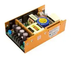


SDS120PS24B-L
AC/DC Open Frame Power Supply (PSU), ITE, 1 Output, 120 W, 90V AC to 264V AC, Fixed
- Manufacturer: XP POWER
- Product type: AC / DC Open Frame Power Supplies
- SVHC: No SVHC (15-Jan-2018)
- Product Range: SDS120 Series
- No. of Outputs: 1 Output
- Input Voltage VAC: 90V AC to 264V AC
- Power Supply Output Type: Fixed
- Output Current - Output 1: 5A
- Output Current - Output 2: -
- Output Current - Output 3: -
- Output Current - Output 4: -
- Output Voltage - Output 1: 24V
- Output Voltage - Output 2: -
- Output Voltage - Output 3: -
- Output Voltage - Output 4: -
- Power Supply Applications: ITE
- Power Rating (Forced Cooling): -
- Power Rating (Convection Cooling): 120W
| Delivery and price | |
|---|---|
| Units per pack | 10 |
| Price | 142.05 € |
| Current stock | 10+ |
| Lead time | 30 days |
**120-150 Watts**

xppower.com

## **SDS Series**

- Convection-cooled

- 3”x 5”Footprint

- Up to 90% Efficiency

- Open Frame, U-Channel & Covered Versions

- Low Temperature Option

- Single & Multi Outputs

- 3 Year Warranty

## **Specif** ~~**ication**~~

## **Input**

- Input Voltage • 90-264 VAC (120-370 VDC) Input Frequency • 47-63 Hz Input Current • 120 W: 1.7 / 1.0 A max at 115 / 230 VAC 150 W: 2.0 / 0.8 A max at 115 / 230 VAC

- Inrush Current • 120 W: 20 / 51 A max at 115 / 230 VAC 150 W: 54 / 63 A max at 115 / 230 VAC

- Power Factor • >0.9 Earth Leakage Current • 120 W: 0.30 / 0.75 mA at 115 / 230 VAC 150 W: 0.40 / 0.75 mA at 115 / 230 VAC

- Input Protection • Internal T3.15 A / 250 VAC fuse in line

## **Output**

- Output Voltage • See table Output Voltage Trim • ±5% output 1 only (3.3 V variant ±10%) Initial Set Accuracy • Single output models: ±1% Multi-output models: ±5%

- Minimum Load • No minimum load required for single output models. For multi-output models (see table)

- Start Up Delay • 2 s max Start Up Rise Time • 2 ms typical Hold Up Time • 16 ms minimum at full load and 110 VAC Line Regulation • 0.5% typical Load Regulation • 3.0% typical Transient Response • 4% max deviation, recovery to within 1% in 500 μ s for a 50% load change

Ripple & Noise • 1% pk-pk typical, 20 MHz bandwidth Overvoltage Protection • 112-132% V1 only, recycle input to reset Overload Protection • All outputs: 110-150% with auto recovery (primary power limit) Short Circuit Protection • Trip & restart (hiccup mode), auto recovery Temperature • ±0.04%/°C Coefficient

## **General**

- Efficiency • 120 W: 80% typical 150 W: 88% typical

- Isolation • 3000 VAC Input to Output, 1500 VAC Input to Ground, 500 VDC Output to Ground

- Isolation Resistance • 50 M Ω Switching Frequency • 120 W: PFC 100 kHz typical, PWM 67 kHz typical. 150 W: PFC 34 kHz minimum, PWM 55 kHz typical. 180 W: PFC 67 kHz typical, PWM 67 kHz typical

- Power Density • 120 W: 4.87 W/In[3] , 150 W: 6.50 W/In[3] Signals • Power Fail Detect = TTL active low, combined AC and DC OK signal (-P versions SDS120 & 150 only) Warning time 16 ms

- MTBF • >130 kHrs to MIL-HDBK-217F at 25 °C, GB

## **Environmental**

- Operating Temperature • 0 °C to +70 °C (-20 °C to +70 °C, SDS180), derate linearly from 100% load at +50 °C to 50% load at +70 °C, for low temperature option add suffix -L: -40 °C to +70 °C, SDS120 and SDS150

- Cooling • Convection-cooled Operating Humidity • 5-95% RH, non-condensing Storage Temperature • -40 °C to +85 °C

## **EMC & Safety**

|**EMC & Safetyy**||
|---|---|
|Emissions|• EN55022, level B conducted & radiated.|
|Harmonic Currents|• EN61000-3-2 class A|
|Voltage Flicker|• EN61000-3-3|
|ESD Immunity|• EN61000-4-2, level 2 contact, Perf Criteria A|
||SDS150: level 3 air, Perf criteria A|
|Radiated Immunity|• EN61000-4-3, level 2, Perf Criteria A|
|EFT/Burst|• EN61000-4-4, level 2, Perf Criteria A|
|Surge|• EN61000-4-5, installation class 3,|
||Perf Criteria A|
|Conducted Immunity|• EN61000-4-6, level 2 , Perf Criteria A|
|Magnetic Field|• EN61000-4-8, 1 A/m, Perf Criteria A|
|Dips & Interruptions|• EN61000-4-11, 30% 10 ms, 60% 100 ms,|
||>95% 5000 ms Perf Criteria A, B, B|
|Safety Approvals|• EN60950-1, UL60950-1,CSA60950-1|
||per cUL, CE & UKCA meets all applicable|
||directives & legislation|


**SDS120**

## ~~**Models and Ratings**~~

**==> picture [525 x 232] intentionally omitted <==**

**----- Start of picture text -----**<br>
Output  Output 1 Output 2 Output 3 Model Number [(2, 4, 5)]<br>Power Vnom Imin Imax Tol. [(1)] Vnom Imin Imax Tol. [(1)] Vnom Imin Imax Tol. [(1)]<br>SS 72.0 W 3.3 V 0.00 A 22.00 A 5% SDS120PS03B<br>120.0 W 12.0 V 0.00 A 10.00 A 3% SDS120PS12B<br>Re es ns PDSS(OU)(QnSC (ICC(O(n<br>Rs 120.0 W 18.0 V 0.00 A eG 6.66 A 3% (O(n (n(n (OC SDS120PS18B<br>es 120.0 W 24.0 V 0.00 A QR 5.00 A 2% (QO (OQ QO ( SDS120PS24B<br>es 120.0 W 28.0 V 0.00 A ns 4.28 A ns 2% (S(O (S(O (a SDS120PS28B<br>SS 79.5 W +3.3 V  SS 1.50 A 15.00 A 5% +5.0 V 0.40 A 6.0 A 5% SDS120PD00B<br>eS 120.0 W +3.3 V 1.50 A a 15.00 A 5% +12.0 V CC 0.20 A 6.0 A 5% CC SDS120PD01B<br>a 120.0 W +5.0 V 1.50 A a 15.00 A 5% +12.0 V CC 0.20 A 6.0 A 5% CC SDS120PD02B<br>es 120.0 W +5.0 V 1.50 A (DQ 15.00 A 5% +15.0 V QO 0.20 A (QS 6.0 A 5% (I (OO ( SDS120PD03B<br>Re 120.0 W +5.0 V es(GG 1.50 A 15.00 A 5% +24.0 V 0.10 A 3.5 A 5% SDS120PD04B<br>es 120.0 W +5.0 V 1.50 A 15.00 A 5% -24.0 V 0.20 A (QO 2.0 A 5% (QO (OO SDS120PD05B<br>a 120.0 W +28.0 V 0.39 A CaQO 3.92 A 5% QQ +5.0 V Ca 0.20 A (QQ 2.0 A GC 5% QO ( SDS120PD06B<br>sn 91.5 W +3.3 V 1.50 A 15.00 A 5% +5.0 V 0.60 A 6.0 A 5% -12.0 V 0.00 A 1.0 A 5% SDS120PT01B<br>ee 120.0 W +3.3 V 1.50 A a 15.00 A 5% QOCC +12.0 V GO 0.60 A 6.0 A 5% +5.0 V CO 0.00 A 0.8 A 5% SDS120PT02B<br>CC 120.0 W +3.3 V 1.50 A 15.00 A 5% +12.0 V 0.60 A 6.0 A 5% -5.0 V 0.00 A 0.8 A 5% SDS120PT03B<br>120.0 W +3.3 V 1.50 A 15.00 A 5% +12.0 V 0.60 A 6.0 A 5% -12.0 V 0.00 A 0.8 A 5% SDS120PT04B<br>Re ss (OG QOeC(QO<br>es 120.0 W +3.3 V 1.50 A QO 15.00 A 5% GG +12.0 V 0.60 A ( 6.0 A C 5% G +12.0 V (COO 0.00 A 0.8 A 5% SDS120PT05B<br>120.0 W +5.0 V 1.50 A 15.00 A 5% +12.0 V 0.60 A 6.0 A 5% +5.0 V 0.00 A 0.8 A 5% SDS120PT06B<br>eeSSC CG<br>SC 120.0 W +5.0 V 1.50 A 15.00 A 5% +12.0 V 0.60 A 6.0 A SC 5% -5.0 V CC 0.00 A 0.8 A 5% SDS120PT07B<br>CC 120.0 W +5.0 V 1.50 A 15.00 A 5% +12.0 V 0.60 A 6.0 A SC 5% -12.0 V CC 0.00 A 0.8 A 5% SDS120PT08B<br>a 120.0 W +5.0 V 1.50 A 15.00 A 5% +15.0 V CC 0.60 A 6.0 A 5% -15.0 V CC 0.00 A 0.8 A 5% SDS120PT10B<br>120.0 W +5.0 V 1.50 A 15.00 A 5% +15.0 V 0.60 A 6.0 A 5% +15.0 V 0.00 A 0.8 A 5% SDS120PT11B<br>es 120.0 W +5.0 V 1.50 A QQ 15.00 A 5% +24.0 V (GG 0.35 A 3.5 A 5% -24.0 V (QO 0.00 A 0.8 A 5% SDS120PT12B<br>Rs 120.0 W +5.0 V GGG 1.50 A 15.00 A 5% +24.0 V 0.35 A 3.5 A 5% +24.0 V 0.00 A 0.8 A 5% SDS120PT13B<br>a 120.0 W +5.0 V 1.50 A SC 15.00 A 5% +24.0 V SC 0.35 A 3.5 A SCQO 5% -12.0 V CC 0.00 A QO 0.8 A 5% SDS120PT14B<br>SC 120.0 W +5.0 V 1.50 A 15.00 A 5% +24.0 V 0.35 A 3.5 A 5% +12.0 V 0.00 A 0.8 A 5% SDS120PT15B<br>ee 120.0 W +5.0 V 1.50 A a 15.00 A 5% CC +10.0 V 0.60 A 6.0 A SC 5% -10.0 V CC 0.00 A 1.0 A 5% SDS120PT16B<br>a 120.0 W +5.0 V SC 1.50 A 15.00 A 5% +10.0 V a 0.60 A CC 6.0 A 5% +10.0 V 0.00 A 1.0 A 5% SDS120PT17B<br>**----- End of picture text -----**<br>


## ~~**Notes**~~

_1. Tol. (total regulation) includes line regulation and load regulation._

_2. For optional PCB only version, delete suffix ‘B’ from model number. Example SDS120PS03._

_3. For non-standard voltages contact sales._

_4. For optional low temperature -40 °C operation, add suffix ‘-L’ to model number. Example: SDS120PS12B-L_

_5. For optional Power Fail Detect circuit, add suffix ‘-P’ to model number, example: SDS120PS12B-P_

## ~~**Mechanical Details**~~

**==> picture [527 x 277] intentionally omitted <==**

**----- Start of picture text -----**<br>
fe iini a 1.18<br>B (30.0) (33.2) [1.30 ]<br>B<br>1.57 (40.0) 0.79 (20.3) 0.21<br>(5.5)<br>4.49 (114.3) 0.25 (6.4)<br>1.5 (39.2)<br>4.55 (115.6)5.00 (127.0) 0.22 (5.7) 0.22 (5.6) (6.35)0.25 Power Fail Detect (PFD)<br>(0.60)0.02 aN C0.3 (ø6.40)ø0.25  (2.45)0.09  (76.6)3.01 i A ©O | | B © B Voltage Adj. f 5o B ©© P2 1 A See section-A (4x) (81.6)3.21 | 0.22(5.6) | +5 V Pin 13 is +5 V for normal opera-tion.  Source current is 5 mA max.<br>M3xP0.5 P (0.60)0.02 e/ = (ø5.40)ø0.21  |  L it~ H1D0.2 \ t (65.3)2.57 | A q InputLNG | AC ©©-—-Ih B o © B — —-—- B —- | IP -§©| A 13 See section-B (11x) { A G1 A H2 M3xP0.50.03(0.8) 0.01(0.3) / Uy / j | PFD is <0.4 V for either  AC Fail (<90 VAC) or DC Fail (<95% Vnom). Sink current is 10 mA max.<br>See section-B (scale 4/1) section-A (scale 4/1)<br>2.7 (68.58) 0.55 0.09 H3 Internal<br>ø0.29  3.9 (99.06) (13.9) (2.5)<br>_ (ø7.44) (0.38)0.01 See section-C (4x) A N G1<br>4.49 (114.25) PIN CONNECTIONS<br>4.00 (101.6) 0.25 (6.35) Pin Single Dual Triple Pin Single Dual Triple<br>ZEITrT ø0.14 (ø3.6) A G2 B — | B :: \ (30.75)1.21  1.i 0.79 (20.3) a 12 V1V1 V2V2 V2V2 89 ReturnReturn CommonCommon CommonCommon<br>See section-C (scale 4/1) R2.0 wy b4 B a 3 V1 V1 V1 10 Return N/C V3<br>1.30  aa 4 V1 V1 V1 11 Return Common Common<br>(33.2) 5 V1 V1 V1 12 Return Common Common<br>a 6 V1 V1 V1 13 PFD [(1)] PFD [(1)] PFD [(1)]<br>0.85 0.15 (4.0) 1.18 (30.02) 7 Return Common Common<br>(21.6) 0.9 0.15 (4.0)<br>(23.0)<br>Notes<br>ø0.21 (5.4)<br>**----- End of picture text -----**<br>


   5. For mating connector kit order part number SDS120/SDS150 CON KIT. 6. For cable harness order part number SDS120S LOOM for single output models & SDS120M LOOM for multi-output models.

1. Optional Power Fail Detect signal on ‘-P’ versions only. Standard models pin 13 is N/C.

2. I/P connector P1 mates with Molex housing 09-50-3051 & Molex 2878 series crimp terminal.

   7. Maximum mounting screw penetration: 0.14 (3.5)

3. O/P P2 mates with Molex housing 09-50-3131 & Molex 2878 series crimp terminal.

   8. All dimensions are in inches (mm).

4. For optional cover kit order part number SDS120 COVER, to receive unit with cover fitted add suffix ‘-C’ to model number, e.g. SDS120PS12B-C (overall height is 1.73 (44.0)).

9. Weight: 0.77-0.99 lbs (350-450 g) approx.

10. For PCB-only version, overall dimensions are max 5.00 x 3.00 x 1.44 (127.0 x 76.2 x 36.6).

**SDS150**

## ~~**Models and Ratings**~~

|Output Power|Output Voltage|Output Current|Output Current|Total Regulation(1)|Model Number(2,4,5,6)|
|---|---|---|---|---|---|
|||Minimum|Maximum|||
|150 W|24 V|0 A|6.25 A|3%|SDS150PS24B|
|150 W|36 V|0 A|4.17 A|2%|SDS150PS36B|


## ~~**Notes**~~

_1. Total regulation includes line regulation and load regulation._

_2. For optional 2 pin Molex input, add suffix ‘-D’ to model number. Example SDS150PS12B-D._

_3. For non-standard voltages contact sales._

_4. For optional low temperature -40 °C operation, add suffix ‘-L’ to model number. Example: SDS150PS12B-L_

_5. For optional PCB only version, delete suffix ‘B’ from model number. Example SDS150PS48._

_6. For optional Power Fail Detect signal (PFD), add suffix ‘-P’ to model number. Example: SDS150PS48B-P._

## ~~**Mechanical Details**~~

## **U Channel**

**==> picture [329 x 450] intentionally omitted <==**

**----- Start of picture text -----**<br>
1.18 (30.0) 0.54 (13.6) M3* P0.5 (Mounting Holes) x 5<br>0.30 (7.7) AC Input 1.18 (30.0)<br>G N L<br>P1<br>5.00<br>(127.0)<br>4.50<br>3.90<br>(114.3)<br>(99.0)<br>tid 13 sere 1 P2 | HL<br>o 2.57 (65.3) o DC Output 0.67  0.25<br>0.55 M3* P0.5 (Mounting Holes) x 4 Pitch = 3.96 mm (16.9) (6.4)<br>(14.0)<br>Voltage<br>Adj.<br>3.21 (81.5)<br>|<br>1.<br>Open Frame<br>M3 x P0.5 (Mounting Holes) x 4 ~ J 1.57 (40.0 E ) . 0.80 (20.3)<br>ø4.0 (Mounting Holes) x 4<br>5.00 (127.0)<br>4.55 (115.6) 0.22 (5.7) 1.40 (35.6)<br>Voltage Adj.<br>P2<br>1<br>DC<br>AC Output<br>L<br>Input N oo |O Pitch = 3.96 mm =|<br>G 13<br>P 1<br>0.12 (3.0)<br>1.21 (30.7) 0.80 (20.3)<br>4.50 (114.3)<br>4.00 (101.6)<br>0.25 (6.4)<br>1.62 (41.2)<br>1.16 (29.6)<br>0.22 (5.5) 0.56 (14.2)<br>3.00 (76.2) 2.57 (65.3) 7.9)(0.32  3.00 (76.2)<br>)(10.90.43<br>1.16 (29.6)<br>**----- End of picture text -----**<br>


|P2 - PIN CONNECTIONS<br>Pin<br>Function<br>Pin<br> Function<br>1<br>V1<br>7<br>Return<br>2<br>V1<br>8<br>Return<br>3<br>V1<br>9<br>Return|
|---|
|4<br>V1<br>10<br>Return<br>5<br>V1<br>11<br>Return<br>6<br>V1<br>12<br>Return<br>13<br>PFD(4)<br>~~**Notes**~~<br>~~oO~~|
|All dimensions in inches (mm), tolerance ±0.02 (±0.5).|
|2. Input connector P1 mates with Molex housing 09-50-3051 and<br>Molex 2478 series crimp terminal.|
|3. Output connector P2 mates with Molex housing 09-50-3131 and|
|Molex 2478 series crimp terminal.<br>4. Optional power fail detect signal on ‘-P’ versions only. Standard<br>models pin 13 is not connected.<br>5. For mating connector kit order part number<br>SDS120/SDS150 CON KIT.<br>6. For cable harness order part number SDS150 LOOM.|
|7. Maximum mounting screw penetration: 0.14 (3.5)|
|8. For optional cover kit order part number SDS150 COVER|
|9. Weight: U Channel - 1.27 lbs (580 g) approx.<br>Open Frame - 0.86 lbs (390 g) approx.|
|Power Fail Detect (PFD)<br>is +5 V for normal operation.<br>Source current is 5 mA max.<br>+5 V<br>Pin 13|
|PFD is <0.4 V for either<br>AC Fail (<90 VAC) or<br>DC Fail (<95% Vnom).<br>Sink current is 10 mA max.|
||
|Internal|


## ~~**Notes**~~

1. All dimensions in inches (mm), tolerance ±0.02 (±0.5).

2. Input connector P1 mates with Molex housing 09-50-3051 and Molex 2478 series crimp terminal.

## **Open Frame**

3. Output connector P2 mates with Molex housing 09-50-3131 and Molex 2478 series crimp terminal.

4. Optional power fail detect signal on ‘-P’ versions only. Standard models pin 13 is not connected.

5. For mating connector kit order part number SDS120/SDS150 CON KIT.

6. For cable harness order part number SDS150 LOOM.

7. Maximum mounting screw penetration: 0.14 (3.5)

8. For optional cover kit order part number SDS150 COVER

9. Weight: U Channel - 1.27 lbs (580 g) approx.

19 Jan 2023
Updated at June 8, 2026
XP Power is a globally recognized leader in the design and manufacture of critical power solutions for the electronics industry. With a steadfast commitment to total quality and in-house engineering expertise, the company delivers highly reliable components that support complex applications across the industrial, healthcare, and technology sectors. Their extensive manufacturing capabilities provide engineers with a broad and dependable source for innovative power products. Our extensive portfolio of XP Power components is heavily focused on robust power and line protection. The core of this offering features a vast selection of high-performance AC/DC converters, designed to meet the rigorous efficiency and footprint demands of modern electronic systems. Complementing these are numerous reliable DC/DC converters, providing versatile options for precise voltage regulation and seamless system integration. Beyond their primary power conversion ranges, XP Power manufactures specialized components to address specific design challenges. Our selection includes essential passive components, such as power line filters for effective EMC and RFI suppression, ensuring signal integrity and strict regulatory compliance. Additionally, we provide dedicated AC/DC LED power supplies tailored for reliable, long-lasting performance in advanced commercial and industrial lighting applications.
About Novapart
Novapart is a B2B electronic component broker specialising in stock shortages and cost reduction. We source hard-to-find parts and identify compliant alternatives across a catalogue of 410,000+ components from 500+ manufacturers.
Learn more →Stock Shortage Specialist
When a component is unavailable, discontinued or has an unacceptable lead time, we tap into our network of vetted European and Asian distributors to source what you need — without compromising on quality or traceability.
Request a quote →Compliant Alternatives
We identify pin-to-pin, electrically equivalent substitutes that meet the same certifications (RoHS, AEC-Q100, REACH) as your original specification — validated against datasheets, not just part numbers. Often at a lower cost.
BOM Analysis service →