
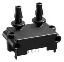


SDP510
Pressure Sensor, Medical, Industrial, Calibrated, 500 Pa, Digital, Differential, 3.3 V, Tube
- Manufacturer: SENSIRION
- Product type: Pressure Transducers
- Port Style: Tube
- Product Range: SDP500 Series
- Sensor Output: Digital
- Voltage Rating: 3.3V
- Operating Pressure Max: 500Pa
- Pressure Measurement Type: Differential
| Delivery and price | |
|---|---|
| Units per pack | 25 |
| Price | 69.26 € |
| Current stock | 10+ |
| Lead time | 30 days |
## **SDP600 Series** (SDP6xx/5xx) Low-cost Digital Differential Pressure Sensor - Accuracy better than 0.2% FS near zero - Digital output (I[2] C) - Excellent repeatability, even below 10 Pa - Calibrated and temperature compensated - Excellent long-term stability - Flow measurement in bypass configuration ## **Product Summary** The SDP600 sensor family is Sensirion’s series of digital differential pressure sensors designed for high-volume applications. They measure the pressure of **air and nonaggressive gases** with superb accuracy and no offset drift. The sensors cover a **pressure range of up to ±500 Pa** (±2 inch H2O / ±5 mbar) and deliver **outstanding accuracy** even at the bottom end of the measuring range. The SDP600 series operates from a 3.3 Vdc supply voltage and features a digital 2-wire interface, which makes it easy to connect directly to a microprocessor. The signal is internally **linearized** and **temperature compensated** . The outstanding performance of these sensors is based on Sensirion’s **patented CMOSens[®] sensor technology** , which combines the sensor element, signal processing and digital calibration on a tiny microchip. The differential pressure is measured by a thermal sensor element using flow-through technology. Compared with membranebased sensors, the SDP600 features an **extended dynamic range** , better **long-term stability** , and improved repeatability, especially near zero. The well-proven CMOS technology is perfectly suited for high-quality mass production and is the ideal choice **for demanding** and **cost-sensitive OEM applications.** ## **Applications** - Medical - HVAC - Automotive - Process automation - Burner control ## **Connection diagram** **==> picture [196 x 67] intentionally omitted <==** **----- Start of picture text -----**<br> Vdd<br>VDD 3.3V<br>C SDA SDP600<br>Series<br>(master)<br>SCL (slave)<br>—__ ©<br>GND<br>**----- End of picture text -----**<br> ## **New versions** - Low pressure versions SDP600/610-125Pa and SDP600/610-25Pa are suited to measure very low and ultra low differential pressure. - Low power versions (SDP606/SDP616) are developed especially for low power battery operation. - Special calibration to measure a massflow in bypass configuration (SDP601/SDP611). ## **OEM options** A variety of custom options can be implemented for highvolume OEM applications. Ask us for more information. SDP600 series with bidirectional digital communication (I[2] C bus) ## **Sensor chip** The SDP600 series features a fourth-generation silicon sensor chip called SF04. In addition to a thermal mass flow sensor element, the chip contains an amplifier, A/D converter, EEPROM memory, digital signal processing circuitry, and interface. The highly sensitive chip requires only a minuscule amount of gas flow through the sensor. 1/10 Version 1.6 – February 2012 www.sensirion.com ## **1. Sensor Performance** ## **1.1 Physical specifications[1]** |Parameter|SDP500<br>SDP510|SDP600-500Pa<br>SDP610-500Pa|SDP600-125Pa<br>SDP610-125Pa|SDP600-25Pa<br>SDP610-25Pa|SDP601<br>SDP611|SDP606<br>SDP616| |---|---|---|---|---|---|---| |Short Description|Low cost|Standard|Low DP|Lowest DP|“Mass Flow”|Low<br>Power2| |Calibrated range3|0 Pa<br>to +500 Pa<br>(0 to 2.0 in. H2O)|– 500 Pa<br>to + 500 Pa<br>(± 2.0 in. H2O)|– 125 Pa<br>to + 125 Pa<br>(± 0.5 in. H2O)|– 25 Pa<br>to + 25 Pa<br>(± 0.1 in. H2O)|– 500 to + 500 Pa<br>(± 2.0 in. H2O)|| |Measurement range<br>~~a~~|– 500 to + 500 Pa<br>(± 2.0 in. H2O)||– 125Pa<br>to + 125 Pa<br>(± 0.5 in. H2O)|– 25 Pa<br>to + 25 Pa<br>(± 0.1 in. H2O)|– 500 to + 500 Pa<br>(± 2.0 in. H2O)<br>~~ee~~|| |Temperature-<br>compensation<br>~~a ee~~<br>~~a~~|yes<br>~~ee~~|yes<br>~~ee~~|yes<br>~~ee~~|yes<br>~~ee~~|mass flow4<br>~~ee~~<br>~~ee~~|yes<br>~~ee~~<br>~~ee~~| |Resolution<br>~~a ee~~<br>~~a~~|12 bits preset5(adjustable from 9 to 16 bit)<br>~~ee~~<br>~~ee~~|||||16 bit<br>~~ee~~<br>~~ee~~| |Zero point accuracy6,7<br>~~a~~|0.2 Pa||0.1 Pa||0.2 Pa<br>~~ee~~|| |Span accuracy6,7<br>~~ee~~<br>~~a~~|4.5% of reading<br>~~ee~~|3% of reading<br>~~ee~~<br>~~ee~~||||| |Zero point<br>repeatability6,7<br>~~ee~~<br>~~a~~|0.1 Pa<br>~~ee~~||0.05 Pa<br>~~ee~~|0.03 Pa<br>~~ee~~<br>~~ee~~|0.1 Pa<br>~~ee~~|| |Span repeatability6,7<br>~~ee~~<br>~~a~~|0.5% of reading<br>~~ee~~<br>~~ee~~|||||| |Offset shift due to<br>temperature variation<br>~~a~~|None<br>(less than resolution)<br>~~ee~~|||||| |Span shift due to<br>temperature variation|< 0.5% of reading per 10°C|||||| |Offset stability<br>~~a~~|< 0.1 Pa/year|||||| |Response time5|4.6 ms typical at 12-bit resolution|||||70 ms<br>typical| |Warm-up time for first<br>reliable measurement|Typ. 50 ms<br>(first measurement typically after 16 ms)|||||N/A| > 1 Unless otherwise noted, all sensor specifications are valid at 25°C with Vdd = 3.3 Vdc and absolute pressure = 966 mbar. > 2 Low Power version are specified at 25°C with Vdd = 3.0 Vdc and absolute pressure = 966 mbar. > 3 The SDP500/SDP510 sensors do measure in the full range from -500 to +500 Pa. But in contrast to the SDP600/SDP610 we do not guarantee the specified accuracy for the negative measurement range for SDP500/SDP510. - 4 Please see chapter 5.3 for details. - 5 See Aplication Note for response times with other resolutions, e.g. 1.3 ms with 10 bits. > 6 With 12-bit resolution; includes repeatability and hysteresis. > 7 Total accuracy/repeatability is a sum of zero-point and span accuracy/repeatability. 2/10 Version 1.6 – February 2012 www.sensirion.com ## **1.2 Ambient conditions** |Parameter|SDP5xx / SDP6xx Series| |---|---| |Calibrated for8|Air, N2| |Media compatibility|Air, N2,O2| |Calibrated temperature<br>range8,9|-20 °C to +80 °C| |Operatingtemperature|-20 °C to +80 °C| |Storage temperature8|-40 °C to +80 °C| |Position sensitivity|Less than repeatabilityerror| ## **1.3 Materials** |Parameter|SDP5xx / SDP6xx Series| |---|---| |Wetted materials|PBT (polybutylene terephthalate), glass<br>(silicon nitride, silicon oxide), silicon, gold,<br>FR4, silicone as static sealing, epoxy,<br>copper alloy, lead-free solder| |REACH, RoHS,<br>WEEE|The SDP5xx/6xx series is REACH, RoHS<br>and WEEE compliant| ||59’780(inch H2O)-1| |---|---| |SDP6x0-25Pa|120’000 mbar-1<br>8’273’719 psi-1<br>298’900(inch H2O)-1| ## **2.2 Electrical characteristics for SDP606 / SDP616 (low power version)** |Parameter|SDP606 / SDP616| |---|---| |Operating voltage|2.7– 3.3 Vdc<br>(A supplyvoltage of 3.0 V is recommended)| |Current drain|< 400A| |Current drain in sleep<br>mode|< 1A| |Interface|Digital 2-wire interface(I2C)| |Bus clock frequency|100 kHz typical, 400 kHz max.| |Default I2C address|64(binary:1000 000)| |Scale factor11|60 Pa-1 (for all 500 Pa versions)| ## **2. Electrical Specifications** ## **2.1 Electrical characteristics** |Parameter|SDP5xx / SDP6xx10| |---|---| |Operating voltage|3.0– 3.6 Vdc<br>(A supplyvoltage of 3.3 V is recommended)| |Current drain|< 6 mA typical in operation| |Interface|Digital 2-wire interface(I2C)| |Bus clock frequency|100 kHz typical, 400 kHz max.| |Default I2C address|64(binary:1000 000)| |**Scale factor11**|| |SDP6xx-500Pa|60 Pa-1| |SDP6x0-125Pa|240 Pa-1| |SDP6x0-25Pa|1200 Pa-1| |Scale factor to<br>alternative units12|For all 500 Pa versions:<br>6’000 mbar-1<br>413’686 psi-1<br>14’945(inch H2O)-1| |SDP 6x0-125Pa|24’000 mbar-1<br>1'654’744psi-1| 8 Contact Sensirion for information about other gases, wider calibrated temperature ranges and higher storage temperatures. 9 Valid for products with serial numbers starting with 1136 000 000. For older products, calibrated temperature range is 0°C to +50°C. 10 For all SDP6xx sensors except for SDP606/SDP616. 11 See section 5.1. The scale factor may vary with other configurations. 12 Instead of the standard scale factor (to get the physical value in Pa), the sensor output may be divided by alternative scale factors to receive the physical value in another unit. 3/10 Version 1.6 – February 2012 www.sensirion.com ## **3. Interface Specifications** The serial interface of the SDP600 series is optimized in terms of sensor readout and power consumption. It is compatible with I[2] C interfaces. For detailed specifications of the I[2] C protocol, see _The I2C Bus Specification_ , Version 2.1, January 2000 (source: NXP). ## **3.1 Interface connection – external components** Bi-directional bus lines are implemented by the devices (master and slave) using open-drain output stages and a pull-up resistor connected to the positive supply voltage. The recommended pull-up resistor value depends on the system setup (capacitance of the circuit or cable and bus clock frequency). In most cases, 10 kΩ is a reasonable choice. The capacitive loads on SDA and SCL line have to be the same. It is important to avoid asymmetric capacitive loads. I[2] C Transmission Start Condition ~~PO~~ **==> picture [179 x 54] intentionally omitted <==** **----- Start of picture text -----**<br> VDD<br>master Rp Rp slave (SDP600)<br>SDA<br>SCL<br>**----- End of picture text -----**<br> Both bus lines, SDA and SCL, are bi-directional and therefore require an external pull-up resistor. ## **3.2 I[2] C Address** The I[2] C address consists of a 7-digit binary value. By default, the I[2] C address is set to 64 (binary: 1000 000). The address is always followed by a write bit (0) or read bit (1). The default hexadecimal I[2] C header for read access to the sensor is therefore h81. ## **3.3 Transfer sequences** **Transmission START Condition (S):** The START condition is a unique situation on the bus created by the master, indicating to the slaves the beginning of a transmission sequence (the bus is considered busy after a START). I[2] C Transmission Start Condition SDA SCL S START condition A HIGH to LOW transition on the SDA line while SCL is HIGH ~~a~~ **Transmission STOP Condition (P):** The STOP condition is a unique situation on the bus created by the master, indicating to the slaves the end of a transmission sequence (the bus is considered free after a STOP). **==> picture [157 x 87] intentionally omitted <==** **----- Start of picture text -----**<br> I [2] C Transmission Stop Condition<br>SDA<br>SCL<br>P<br>STOP condition<br>**----- End of picture text -----**<br> A LOW to HIGH transition on the SDA line while SCL is HIGH. ~~po~~ **Acknowledge (ACK) / Not Acknowledge (NACK):** Each byte (8 bits) transmitted over the I[2] C bus is followed by an acknowledge condition from the receiver. This means that after the master pulls SCL low to complete the transmission of the 8th bit, SDA will be pulled low by the receiver during the 9th bit time. If after transmission of the 8th bit the receiver does not pull the SDA line low, this is considered to be a NACK condition. If an ACK is missing during a slave to master transmission, the slave aborts the transmission and goes into idle mode. ## I[2] C Acknowledge / Not Acknowledge **==> picture [233 x 93] intentionally omitted <==** **----- Start of picture text -----**<br> not acknowledge<br>SDA<br>acknowledge<br>SCL R/_W ACK D7 D0 ACK<br>Each byte is followed by an acknowledge or a not<br>acknowledge, generated by the receiver<br>a<br>**----- End of picture text -----**<br> **Handshake procedure (Hold Master):** In a master-slave system, the master dictates when the slaves will receive or transmit data. However, in some situations a slave device may need time to store received data or prepare data to be transmitted. Therefore, a handshake procedure is required to allow the slave to indicate termination of internal processing. **==> picture [233 x 79] intentionally omitted <==** **----- Start of picture text -----**<br> I [2] C Hold Master<br>PO<br>SDA<br>a ee one on<br>SCL R/_W ACK D7 D0 ACK<br>Hold master:<br>SCK line pulled LOW data ready: SCK line released<br>**----- End of picture text -----**<br> After the SCL pulse for the acknowledge signal, the SDP600 series sensor (slave) can pull down the SCL line to force the master into a wait state. By releasing the SCL line, the sensor indicates that its internal processing is completed and transmission can resume. (The bold lines indicate that the sensor controls the SDA/SCL lines.) 4/10 Version 1.6 – February 2012 www.sensirion.com ## **3.4 Data transfer format** the second result byte. The sensor checks whether the master sends an acknowledge after each byte and aborts the transmission if it does not. Data is transferred in byte packets in the I[2] C protocol, which means in 8-bit frames. Each byte is followed by an acknowledge bit. Data is transferred with the most significant bit (MSB) first. I[2] C Measurement ~~PO~~ _8-bit command code:_ _**hF1**_ Command: **Trigger differential pressure measurement** A data transfer sequence is initiated by the master generating the Start condition (S) and sending a header byte. The I[2] C header consists of the 7-bit I[2] C device address and the data direction bit (R/_W). |||1|2|3<br>4<br>5||6|7||8|9|10|11|12<br>13<br>14<br>15<br>16|17|18|||1<br>2<br>3<br>4<br>5<br>6<br>7<br>8<br>9|||| |---|---|---|---|---|---|---|---|---|---|---|---|---|---|---|---|---|---|---|---|---|---| ||S|1|I2CAdr<br>0<br>0<br>0<br>0<br>~~am~~|||0|0||**W**<br>0|**ACK**|1|1|1<br>1<br>0<br>0<br>0 <br>Command<br>~~|~~|1|**ACK**|||S<br>**ACK**<br>**Hold Master**<br>**R**<br>1<br>0<br>0<br>0<br>0<br>0<br>0<br>I2CAdr<br>1<br>~~m8~~|||| |Hatched areas indicate that the sensor controls the SDA line||||||||13<br>12<br>18<br>19<br>22<br>21<br>27<br>**MSByte MeasData**<br>**LSByte MeasData**<br>11<br>14<br>15<br>16<br>17<br>20<br>23<br>24<br>25<br>26<br>ACK<br>ACK<br>28<br>31<br>30<br>**Check Byte**<br>29<br>32<br>33<br>34<br>35<br>10<br>Hatched areas indicate that the sensor controls the SDA line.||||||||||||36<br>ACK|P| The value of the R/_W bit in the header determines the data direction for the rest of the data transfer sequence. If R/_W = 0 (WRITE) the direction remains master-to-slave, while if R/_W = 1 (READ) the direction changes to slaveto-master after the header byte. ## **4.2 Soft reset** This command forces a sensor reset without switching the power off and on again. On receipt of this command, the sensor reinitializes the control/status register contents from the EEPROM and starts operating according to these settings. ## **4. Command Set and Data Transfer Sequences** ## I[2] C Soft Reset _8-bit command code:_ _**hFE**_ Command: **Soft reset** 1 2 3 4 5 6 7 8 9 10 11 12 13 14 15 16 17 18 S 1 0 0 0 0 0 0 0 1 1 1 1 1 1 1 0 system reboot **W** I2CAdr Command ~~oo~~ **4.3 CRC-8 Redundant Data Transmission** **==> picture [492 x 124] intentionally omitted <==** If a correctly addressed sensor recognizes a valid command and access to this command is granted, it responds by pulling down the SDA line during the subsequent SCL pulse for the acknowledge signal (ACK). Otherwise it leaves the SDA line unasserted (NACK). Cyclic redundancy checking (CRC) is a popular technique used for error detection in data transmission. The transmitter appends an n-bit checksum to the actual data sequence. The checksum holds redundant information about the data sequence and allows the receiver to detect transmission errors. The computed checksum can be regarded as the remainder of a polynomial division, where the dividend is the binary polynomial defined by the data sequence and the divisor is a “generator polynomial”. The two most important commands are described in this data sheet, and the data transfer sequences are specified. Contact Sensirion for advanced sensor options. ## **4.1 Measurement triggering** The SF04 sensor implements the CRC-8 standard based on the generator polynomial Each individual measurement is triggered by a separate read operation. x[8] + x[5] + x[4] +1. Note that two transfer sequences are needed to perform a measurement. First write command byte hF1 (trigger measurement) to the sensor, and then execute a read operation to trigger the measurement and retrieve the flow or differential pressure information. Note that CRC protection is only used for date transmitted from the slave to the master. For details regarding cyclic redundancy checking, please refer to the relevant literature. On receipt of a header with R/_W=1, the sensor generates the Hold Master condition on the bus until the first measurement is completed (see Section 3.3 for timing). After the Hold Master condition is released, the master can read the result as two consecutive bytes. A CRC byte follows if the master continues clocking the SCL line after 5/10 Version 1.6 – February 2012 www.sensirion.com ## **5. Conversion to Physical Values** ## **5.1 Signal scaling and physical unit** The calibrated signal read from the sensor is a signed INTEGER number (two's complement number). The INTEGER value can be converted to the physical value by dividing it by the scale factor (pressure = sensor output scale factor). The scale factor is specified in Section 2.1. ## **5.2 Temperature compensation** The SDP600 sensor series features digital temperature compensation. The temperature is measured on the CMOSens[®] chip by an on-chip temperature sensor. This data is fed to a compensation circuit that is also integrated on the CMOSens[®] sensor chip. No external temperature compensation is necessary. ## **5.3 Mass flow temperature compensation** A sensor output proportional to mass flow is necessary for measuring mass flow in a bypass configuration. Even though the output of the SDP sensors with mass flow temperature compensation is still differential pressure, the temperature compensation is adapted especially for mass flow measurements in a bypass configuration. At calibration temperature both calibrations are equivalent. Please find the application note “Measuring Flow in a Bypass Configuration” on our website **.** ## **5.4 Altitude correction** The SDP600 sensor series achieves its unsurpassed performance by using a dynamic measurement principle. The applied differential pressure forces a small flow of gas through the sensor, which is measured by the flow sensor element. As a result, any variation in gas density affects the sensor reading. While temperature effects are compensated internally, variations in atmospheric pressure (elevation above sea level) can be compensated by a correction factor according to the following formula: DPeff = DPsensor (Pcal / Pamb) DPeff: Effective differential pressure DPsensor: Differential pressure indicated by the sensor Pcal: Absolute pressure at calibration (966 mbar) Pamb: Actual ambient absolute pressure. |1500|842|1.15| |---|---|---| |2250|766|1.26| |3000|697|1.38| **Example:** At 750 m above sea level and a sensor reading of 40 Pa, the effective differential pressure is 41.8 Pa. **Note:** In many HVAC applications such as air flow measurement in a bypass configuration, the described dependence on absolute pressure is actually welcome because the quantity that must effectively be controlled is the mass flow and not the volume flow. Mas flow is dependent on differential pressure and absolute pressure. For details please refer to our application note “Measuring Flow in a Bypass Configuration”. ## **6. OEM Options** A variety of custom options can potentially be implemented for high-volume OEM applications. _None of these options is available with the standard sensors._ Contact Sensirion for more information. ## **6.1 Switch function** A switch version with a programmable trigger level and programmable hysteresis can be realized. ## **6.2 Temperature measurement** The sensor temperature can be read out via the digital interface. ## **6.3 Vdd measurement** The value of the supply voltage Vdd can be read out via the digital interface. ## **6.4 Broken sensor element detection** Breakage of the sensor element can be detected by a sensor chip self-test. ## **6.5 Customer-specific interface** For analog voltage output, please contact Sensirion. ## Altitude correction factors: |Altitude<br>[meters]|Ambient pressure (Pamb)<br>[mbar]|Correction factor<br>(Pcal/ Pamb)| |---|---|---| |0|1013|0.95| |250|984|0.98| |425|966|1.00| |500|958|1.01| |750|925|1.04| 6/10 Version 1.6 – February 2012 www.sensirion.com ## **7. Mechanical Specifications** ## **7.4 SDP610/SDP510 – Tube connection** ## **7.1 Mechanical concept** The SDP600 Series is designed for through-hole technology and can be wave-soldered or hand-soldered to a PCB. - The SDP60x/SDP500 can be directly connected to a manifold using two O-rings. - The SDP61x/SDP510 sensors have ports for connecting standard-size plastic tubes. ## **7.2 Mechanical characteristics** |Parameter|SDP510/SDP610|SDP500/SDP600| |---|---|---| |PCB attachment|Clip-in and hand or wave soldering.<br>Additional mechanical attachment<br>dependingon force requirements|| |Allowable<br>overpressure|1 bar (100 kPa, 400 inches H2O)|| |Rated burstpressure|> 5 bar|| |Gas flow through<br>sensor|< 150 ml/min|| |Weight|< 6g|| |Protection rating|IP 30|| **Figure 3:** SDP610/SDP510 version with ports for tube connection. All dimensions are in mm. ## **7.5 Pin assignments** ## **7.3 SDP600/SDP500 – Manifold connection** Data GND VDD Clock **Figure 4:** Digital output pin assignments (bottom view). ## **7.6 Footprint** **Figure 1:** SDP600/SDP500 manifold mount version. All dimensions are in mm. Sensirion recommends O-rings with the following dimensions: **==> picture [49 x 23] intentionally omitted <==** **Figure 5:** Footprint for PCB mounting. (top view = sensor side). All dimensions in mm. A: Overall sensor dimensions **Figure 2:** Cross section of recommended O-ring B: Holes for additional mounting screws (optional) 7/10 Version 1.6 – February 2012 www.sensirion.com ## **8. Instructions for Use** ## **8.1 Soldering instructions** Standard wave soldering systems may be used for soldering SDP600 series sensors. Reflow soldering is **not** feasible and may damage the sensor. The sensor ports must be protected from solder splash and flux during soldering. Figure 6 shows an appropriate temperature profile with maximum temperature values. **==> picture [218 x 140] intentionally omitted <==** **----- Start of picture text -----**<br> Entrance to solder Exit from solder<br>(Time in wave < 2 s)<br>Flux zone Preheat zone<br>Solder Wave Peak<br>250°C<br>Temp. max. 260°C<br>200°C Approx. PCB<br>150°C bottom-side temp. Max 145°C<br>100°C<br>50°C PCB top-side<br>temperature<br>0°C<br>Start Approx.<br>1 min<br>**----- End of picture text -----**<br> **Figure 6:** Suitable wave soldering profile. The characteristics of wave soldering machines vary, so any soldering setup must be tested before production use. ## **8.2 Sensor handling** The sensors of the SDP600 series are designed to be robust and vibration resistant. Nevertheless, the accuracy of the high-precision SDP600 series can be degraded by rough handling. Sensirion does not guarantee proper operation in case of improper handling. **Note:** avoid applying any mechanical stress to the solder joints of the sensor during or as a result of PCB assembly. **Figure 7:** Supplementary bracket for the SDP600 series. ## **8.4 Air flow and tubing** Due to the dynamic measurement principle, a small air flow is required. **==> picture [230 x 144] intentionally omitted <==** **----- Start of picture text -----**<br> +120<br>0<br>-120<br>-600 0 +600<br>Pressure difference (Pa)<br>Flow (ml/min)<br>**----- End of picture text -----**<br> **Figure 8:** Typical air flow through the SDP6x0. Note: 1 sccm = 1 cm3/min at 0°C and 1013 mbar (1 sccm = 0.001 standard liter). This air flow through the sensor creates a dependence on the tube length. The error is less than 1% with a tube length up to 1 m (with 3/16 inch inside diameter). The sensor ships in an antistatic package to prevent electrostatic discharge (ESD), which can damage the part. To avoid such damage, ground yourself using a grounding strap or by touching a grounded object. Furthermore store the parts in the antistatic package when not in use. ## **8.3 Additional attachment** If necessary, the robustness of the sensor attachment to the PCB can be increased by using a bracket as shown in Figure 7. Sensirion recommends using this additional bracket when the sensor is fitted to a PCB. The bracket must be secured before the pins are soldered to the PCB, as otherwise sensor performance may be degraded by mechanical stress. 8/10 Version 1.6 – February 2012 www.sensirion.com ## **9. Ordering Information** Use the part names and item numbers shown in the following table when ordering SDP600 series differential pressure sensors. For the latest product information and local distributors, visit www.sensirion.com. |Part name|Description /<br>Output|Calibrated range|“Mass flow “|Span accuracy|Product number<br>1-100xxx-xx| |---|---|---|---|---|---| |SDP500|I2C, manifold<br>mount|0 to +500 Pa<br>(0 to +2 in. H2O)|4.5% 601-01|4.5% 601-01|4.5% 601-01| |SDP510|I2C, tube<br>connection|0 to +500 Pa<br>(0 to +2 in. H20)|4.5% 602-01|4.5% 602-01|4.5% 602-01| |SDP600-500Pa|I2C, manifold<br>mount|±500 Pa<br>(±2 in. H2O)||3% 456-01|3% 456-01| |SDP610-500Pa|I2C, tube<br>connection|±500 Pa<br>(±2 in. H20)||3% 455-01|3% 455-01| |SDP600-125Pa|I2C, manifold<br>mount|±125 Pa<br>(±0.5 in. H2O)||3% 760-01|3% 760-01| |SDP610-125Pa|I2C, tube<br>connection|±125 Pa<br>(±0.5 in. H20)||3% 761-01|3% 761-01| |SDP600-25Pa|I2C, manifold<br>mount|±25 Pa<br>(±0.1 in. H2O)||3% 758-01|3% 758-01| |SDP610-25Pa|I2C, tube<br>connection|±25 Pa<br>(±0.1 in. H20)||3% 759-01|3% 759-01| |SDP601-500Pa|I2C, manifold<br>mount|±500 Pa<br>(±2 in. H2O)|x|3% 603-01|3% 603-01| |SDP611-500Pa|I2C, tube<br>connection|±500 Pa<br>(±2 in. H20)|x|3% 604-01|3% 604-01| |Low Power Version|||||| |SDP606|I2C, manifold<br>mount|±500 Pa<br>(±2 in. H2O)||3% 756-01|3% 756-01| |SDP616|I2C, tube<br>connection|±500 Pa<br>(±2 in. H20)||3% 757-01|3% 757-01| |OEM versions|||||| |SDP7xx|Customer<br>specific||||n/a| Packaging units: 80 items/tray and 480 items/box. ## **9.1 Packaging** **Housing:** The sensor housing consists of PBT. The device is fully RoHS compliant – it is free of Pb, Cd, Hg, Cr(6+), PBB and PBDE. **==> picture [199 x 48] intentionally omitted <==** **----- Start of picture text -----**<br> Sensor type<br>SENSIRION aw Sensirion<br>SDPxxx <br>product number<br>PN: 1-100xxx-01 <br> Serial number<br>SN: xxxxxxxxxx <br>t<br>**----- End of picture text -----**<br> **Figure 9:** Marking of the housing. **Traceability Information:** SDPxxx are shipped in trays of 80pcs. The tray dimension is 355mm x 255mm x 21.5mm. By piling them up, the height per tray can be considered as 19mm. For traceability, each tray is marked with a label. No information can be derived from the code directly, respective data is stored at Sensirion AG and is provided upon request. **==> picture [226 x 100] intentionally omitted <==** **----- Start of picture text -----**<br> Sensor type<br> Sensirion item<br>SDPxxx <br>number<br>1-100xxx-01 Lot number<br>xxxxxxxx 80 Number of<br>sensors inside<br> tray<br> Barcode of lot<br>number<br>**----- End of picture text -----**<br> Figure 10: Label sticking on each tray ## **Revision history** |Date|Author|Version|Version<br>Changes| |---|---|---|---| |Sept , 2008 PHA|t , 2008 PHA|V1.0|Initial release| |Nov, 2008|PHA|V1.1|Small amendments (power<br>consumption, asymmetric lines and US<br>office address)| |Jan, 2009|PHA|V1.2|Explanation to SDP5x0 calibration<br>range, media compatibilityextended| |Feb, 2009|PHA|V1.3|Packaging information added, sensor<br>handlinginstruction| |Nov, 2009|PHA|V1.4|Zero point accuracy changed. Supply<br>voltage requirements and<br>recommendations relaxed.| |January,<br>2011|DAT|V1.5|Introduction of low power<br>versions(SDP6x6) and low differential<br>pressure versions SDP6xx-125Pa /<br>SDP6xx-25Pa.| |Feb, 2011|VVO|V1.6|Calibrated Temperature Range is<br>extended, minor corrections| Each sensor is labeled by laser printing on the front side: 9/10 Version 1.6 – February 2012 www.sensirion.com ## **Important Notices** ## **Warning, personal injury** **Do not use this product as safety or emergency stop devices or in any other application where failure of the product could result in personal injury (including death). Do not use this product for applications other than its intended and authorized use. Before installing, handling, using or servicing this product, please consult the datasheet and application notes. Failure to comply with these instructions could result in death or serious injury.** If the Buyer shall purchase or use SENSIRION products for any unintended or unauthorized application, Buyer shall defend, indemnify and hold harmless SENSIRION and its officers, employees, subsidiaries, affiliates and distributors against all claims, costs, damages and expenses, and reasonable attorney fees arising out of, directly or indirectly, any claim of personal injury or death associated with such unintended or unauthorized use, even if SENSIRION shall be allegedly negligent with respect to the design or the manufacture of the product. ## **ESD Precautions** The inherent design of this component causes it to be sensitive to electrostatic discharge (ESD). To prevent ESD-induced damage and/or degradation, take customary and statutory ESD precautions when handling this product. See application note “Handling Instructions” for more information. ## **Warranty** SENSIRION warrants solely to the original purchaser of this product for a period of 12 months (one year) from the date of delivery that this product shall be of the quality, material and workmanship defined in SENSIRION’s published specifications of the product. Within such period, if proven to be defective, SENSIRION shall repair and/or replace this product, in SENSIRION’s discretion, free of charge to the Buyer, provided that: - notice in writing describing the defects shall be given to SENSIRION within fourteen (14) days after their appearance; - such defects shall be found, to SENSIRION’s reasonable satisfaction, to have arisen from SENSIRION’s faulty design, material, or workmanship; - the defective product shall be returned to SENSIRION’s factory at the Buyer’s expense; and This warranty does not apply to any equipment which has not been installed and used within the specifications recommended by SENSIRION for the intended and proper use of the equipment. EXCEPT FOR THE WARRANTIES EXPRESSLY SET FORTH HEREIN, SENSIRION MAKES NO WARRANTIES, EITHER EXPRESS OR IMPLIED, WITH RESPECT TO THE PRODUCT. ANY AND ALL WARRANTIES, INCLUDING WITHOUT LIMITATION, WARRANTIES OF MERCHANTABILITY OR FITNESS FOR A PARTICULAR PURPOSE, ARE EXPRESSLY EXCLUDED AND DECLINED. SENSIRION is only liable for defects of this product arising under the conditions of operation provided for in the datasheet and proper use of the goods. SENSIRION explicitly disclaims all warranties, express or implied, for any period during which the goods are operated or stored not in accordance with the technical specifications. SENSIRION does not assume any liability arising out of any application or use of any product or circuit and specifically disclaims any and all liability, including without limitation consequential or incidental damages. All operating parameters, including without limitation recommended parameters, must be validated for each customer’s applications by customer’s technical experts. Recommended parameters can and do vary in different applications. SENSIRION reserves the right, without further notice, (i) to change the product specifications and/or the information in this document and (ii) to improve reliability, functions and design of this product. Copyright © 2001-2011, SENSIRION. CMOSens[®] is a trademark of Sensirion All rights reserved ## **REACH, RoHS and WEEE Statement** The SDP600 Series complies with requirements of the following directives: - EU Directive 1907/2006/EC concerning Registration, Evaluation, Authorization and Restriction of Chemicals (REACH) - EU Directive 2002/96/EC on waste electrical and electronic equipment (WEEE), OJ13.02.2003; esp. its Article 6 (1) with Annex II. - EU Directive 2002/65/EC on the restriction of certain hazardous substances in electric and electronic equipment (RoHS), OJ01.01.2011 - the warranty period for any repaired or replaced product shall be limited to the unexpired portion of the original period. ## Headquarters and Subsidiaries SENSIRION AG Laubisruetistr. 50 CH-8712 Staefa ZH Switzerland Sensirion Inc., USA phone: +1 805 409 4900 info_us@sensirion.com www.sensirion.com Sensirion Korea Co. Ltd. phone: +82 31 345 0031 3 info@sensirion.co.kr www.sensirion.co.kr phone: +41 44 306 40 00 fax: +41 44 306 40 30 info@sensirion.com www.sensirion.com Sensirion Japan Co. Ltd. phone: +81 3 3444 4940 info@sensirion.co.jp www.sensirion.co.jp Sensirion China Co. Ltd. phone: +86 755 8252 1501 info@sensirion.com.cn www.sensirion.com.cn Sensirion AG (Germany) phone: +41 44 927 11 66 info@sensirion.com www.sensirion.com To find your local representative, please visit www.sensirion.com/contact 10/10 Version 1.6 – February 2012 www.sensirion.com
Updated at February 9, 2023
Sensirion AG is a premier manufacturer of high-quality digital microsensors and systems. Founded in 1998 as a spin-off from the Swiss Federal Institute of Technology Zurich, the company has established a global reputation for its innovative sensor solutions. Sensirion components are widely utilized across demanding applications in the medical, industrial, automotive, and HVAC sectors. A defining feature of the brand is its patented CMOSens Technology, which seamlessly integrates the sensor element, logic circuitry, calibration data, and a digital interface onto a single microchip. This advanced integration is particularly evident in Sensirion’s highly accurate pressure sensors and transducers, which represent our primary offering from the brand. These differential pressure sensors deliver exceptional precision, rapid response times, and long-term stability for critical measurement and control tasks. Backed by rigorous quality standards, including ISO/TS 16949, Sensirion consistently provides dependable and intelligent system solutions. Whether deployed in complex analytical instruments or industrial automation, Sensirion's cutting-edge transducer technologies empower engineers to achieve superior accuracy and system reliability.
About Novapart
Novapart is a B2B electronic component broker specialising in stock shortages and cost reduction. We source hard-to-find parts and identify compliant alternatives across a catalogue of 410,000+ components from 500+ manufacturers.
Learn more →Stock Shortage Specialist
When a component is unavailable, discontinued or has an unacceptable lead time, we tap into our network of vetted European and Asian distributors to source what you need — without compromising on quality or traceability.
Request a quote →Compliant Alternatives
We identify pin-to-pin, electrically equivalent substitutes that meet the same certifications (RoHS, AEC-Q100, REACH) as your original specification — validated against datasheets, not just part numbers. Often at a lower cost.
BOM Analysis service →