
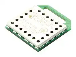


SC14WAMDECT SF01T
Public Address System & Tour Guide System Module, 1Kbps, 1.93 GHz, -93dBm, 2.1V to 3.45V, UART
- Manufacturer: RENESAS
- Product type: RF Transceivers - Sub 2.4GHz ISM Band
- Data Rate Max: 1Kbps
- Frequency Max: 1.93GHz
- Transmit Power: 23dBm
- Sensitivity dBm: -93dBm
- Module Interface: UART
- Supply Voltage Max: 3.45V
- Supply Voltage Min: 2.1V
- RF Transceiver Applications: Public Address System and Tour Guide System
| Delivery and price | |
|---|---|
| Units per pack | 1 |
| Price | 8.0 € |
| Current stock | 10+ |
| Lead time | 30 days |
**SC14WAMDECT SF** **FINAL** ## **Wireless Audio Module** ## **General description** The SC14WAMDECT SF is a Cordless Audio Module with an integrated baseband, radio transceiver, power amplifier and crystal to be used in cordless microphone applications in the DECT frequency band. This module is intended for users with little or no DECT experience, who wish to make a wireless audio system. The module can be configured for various audio applications. A _Public Address System_ has two portable parts (PP) with two microphones and one fixed part (FP) configured as a receiver and integrated into a loudspeaker. Another application is a _Tour Guide System_ where one a microphone (FP) broadcasts to up to 128 receivers (PP) with an integrated loudspeaker or a headset connected. The SC14WAMDECT SF module is suitable for both FP and PP usage: a hardware pin selects the function of the module. The SC14WAMDECT SF module is pre-approved for use in all countries that use the DECT frequency band, as well as the DECT 6.0 frequency band used in North America. ## **Features** - Pre-programmed and ready-to-use module - Antenna embedded, support for external antennas - High quality audio sampled at 25.6 kHz - Latency: 14.2 ms (PA mode), 18.3 ms (TG mode) - UART data transfer (up to 1 kbit/s) in TG mode - Access code for secure registration in TG mode - ETSI (DECT) and FCC (DECT 6.0) certified - Japan DECT (J-DECT) pre-certified - Supports 1.9 GHz and 1.7 GHz DECT bands - Receiver sensitivity < -93 dBm - Transmit power EU: 23 dBm, USA: 20 dBm, JPN: 20 dBm - Power supply voltage: 2.1 V to 3.45 V - Supports NiMH and Alkaline batteries - Small form factor (19.6 mm x 18.0 mm x 2.7 mm) - Operating temperature range: -40 °C to +85 °C ## **Applications** - Public Address System with one or two microphones (transmitter) and one loudspeaker (receiver) - Tour Guide System with one microphone (transmitter) and up to 128 headsets (receiver) ## **________________________________________________________________________________________________** ## **System diagram** **==> picture [311 x 219] intentionally omitted <==** **----- Start of picture text -----**<br> PP<br>Receiver<br>S T Je<br>1 or 2 transmitters FP<br>PP<br>Public Address System<br>w e i<br>Transmitter<br>PP<br>FP<br>N O 2 1 to 128 receivers<br>PP<br>PP<br>S k<br>Tour Guide System<br>**----- End of picture text -----**<br> **Revision 3.0** **23-Jul-2015** **Datasheet** CFR0011-120-00-FM Rev 5 1 of 36 © 2013 Dialog Semiconductor **FINAL** ## **SC14WAMDECT SF** ## **Wireless Audio Module** ## **Table of Contents** **==> picture [219 x 617] intentionally omitted <==** **----- Start of picture text -----**<br> ||| |---|---| |1.0|Connection diagram. . . . . . . . . . . . . . . . . . . . . . . . 3| |1.1|PIN DESCRIPTION. . . . . . . . . . . . . . . . . . . . . . 4| |2.0|Introduction . . . . . . . . . . . . . . . . . . . . . . . . . . . . . . 7| |2.1|SCOPE . . . . . . . . . . . . . . . . . . . . . . . . . . . . . . . 7| |2.2|REFERENCES . . . . . . . . . . . . . . . . . . . . . . . . . 7| |2.3|GLOSSARY AND DEFINITIONS . . . . . . . . . . . 7| |3.0|Wireless Audio Module functions. . . . . . . . . . . . . 8| |3.1|DECT. . . . . . . . . . . . . . . . . . . . . . . . . . . . . . . . . 8| |3.2|MICROPHONE CONFIGURATION . . . . . . . . . 8| |3.3|LOUDSPEAKER CONFIGURATION . . . . . . . . 9| |3.4|FUNCTIONAL OVERVIEW . . . . . . . . . . . . . . . 10| |4.0|Functional description. . . . . . . . . . . . . . . . . . . . . 11| |4.1|AUDIO CONFIGURATION . . . . . . . . . . . . . . . .11| |4.1.1|Microphone connection . . . . . . . . . . . . . .11| |4.1.2|Audio equalisation . . . . . . . . . . . . . . . . . .11| |4.2|POWER MANAGEMENT . . . . . . . . . . . . . . . . .11| |4.3|OUT-OF-RANGE HANDLING . . . . . . . . . . . . . .11| |4.4|PREAMBLE ANTENNA DIVERSITY. . . . . . . . .11| |4.5|REGISTRATION . . . . . . . . . . . . . . . . . . . . . . . 12| |4.5.1|Handling product identities . . . . . . . . . . 12| |4.5.2|Access code . . . . . . . . . . . . . . . . . . . . . 12| |4.6|DEREGISTRATION . . . . . . . . . . . . . . . . . . . . 12| |4.7|DATA TRANSFER. . . . . . . . . . . . . . . . . . . . . . 12| |5.0|Usage guidelines . . . . . . . . . . . . . . . . . . . . . . . . . 13| |5.1|PUBLIC ADDRESS MODE . . . . . . . . . . . . . . . 14| |5.1.1|Microphone (PP) . . . . . . . . . . . . . . . . . . 14| |5.1.2|Loudspeaker (FP) . . . . . . . . . . . . . . . . . 14| |5.1.3|LED indication . . . . . . . . . . . . . . . . . . . . 14| |5.1.4|Volume control . . . . . . . . . . . . . . . . . . . . 14| |5.1.5|Accessory input/output . . . . . . . . . . . . . 14| |5.2|TOUR GUIDE MODE . . . . . . . . . . . . . . . . . . . 14| |5.2.1|Microphone (FP) . . . . . . . . . . . . . . . . . . 14| |5.2.2|Headphone (PP) . . . . . . . . . . . . . . . . . . 14| |5.2.3|LED indication . . . . . . . . . . . . . . . . . . . . 14| |5.2.4|Volume control . . . . . . . . . . . . . . . . . . . . 14| |5.2.5|Accessory input/output . . . . . . . . . . . . . 15| |5.2.6|API (Tour Guide mode only) . . . . . . . . . 15| |5.3|REGISTRATION . . . . . . . . . . . . . . . . . . . . . . . 15| |5.4|DEREGISTRATION . . . . . . . . . . . . . . . . . . . . 15| |5.5|BATTERY LOW DETECTION . . . . . . . . . . . . . 15| |5.6|ANTENNA OPERATION . . . . . . . . . . . . . . . . . 15| |5.6.1|Internal antenna only . . . . . . . . . . . . . . . 15| **----- End of picture text -----**<br> ## 5.6.2 Internal and external antenna with FAD. 15 **==> picture [219 x 537] intentionally omitted <==** **----- Start of picture text -----**<br> ||| |---|---| |6.0|Specifications. . . . . . . . . . . . . . . . . . . . . . . . . . . . 16| |6.1|GENERAL . . . . . . . . . . . . . . . . . . . . . . . . . . . . 16| |6.2|ABSOLUTE MAXIMUM RATINGS . . . . . . . . . 16| |6.3|OPERATING CONDITIONS . . . . . . . . . . . . . . 17| |6.4|SUPPLY CURRENTS . . . . . . . . . . . . . . . . . . . 17| |6.5|DIGITAL INPUT/OUTPUT PINS . . . . . . . . . . . 18| |6.6|ANALOG FRONT END . . . . . . . . . . . . . . . . . . 19| |6.7|AUDIO PERFORMANCE . . . . . . . . . . . . . . . . 21| |6.8|BASEBAND PART . . . . . . . . . . . . . . . . . . . . . 22| |6.9|RADIO (RF) PART . . . . . . . . . . . . . . . . . . . . . 23| |6.10|RF POWER SUPPLY . . . . . . . . . . . . . . . . . . 23| |6.11|RF CHANNEL FREQUENCIES. . . . . . . . . . . 24| |7.0|Design guidelines. . . . . . . . . . . . . . . . . . . . . . . . . 25| |7.1|PCB DESIGN GUIDELINES . . . . . . . . . . . . . . 25| |7.2|MODULE PLACEMENT ON THE MAIN BOARD| |25| |7.3|PATTERN FOR PIN 79 ON THE MAIN BOARD.| |26| |7.4|PRECAUTIONS REGARDING UNINTENDED| |COUPLING . . . . . . . . . . . . . . . . . . . . . . . . . . . 26| |8.0|Example application diagrams . . . . . . . . . . . . . . 27| |9.0|Notices to OEM. . . . . . . . . . . . . . . . . . . . . . . . . . . 29| |9.1|FCC REQUIREMENTS REGARDING THE END| |PRODUCT AND THE END USER . . . . . . . . . 29| |9.2|INDUSTRY CANADA REQUIREMENTS RE-| |GARDING THE END PRODUCT AND THE END| |USER . . . . . . . . . . . . . . . . . . . . . . . . . . . . . . . 29| |9.3|END APPLICATION APPROVAL . . . . . . . . . . 30| |9.4|SAFETY REQUIREMENTS. . . . . . . . . . . . . . . 30| |10.0|Package information . . . . . . . . . . . . . . . . . . . . . 31| |10.1|SOLDERING PROFILE. . . . . . . . . . . . . . . . . 31| |10.2|MOISTURE SENSITIVITY LEVEL (MSL) . . . 31| |10.3|COPPER PAD, SOLDER OPENING AND| |STENCIL . . . . . . . . . . . . . . . . . . . . . . . . . . . . . 32| |10.4|MECHANICAL DIMENSIONS . . . . . . . . . . . . 34| |11.0|Revision history . . . . . . . . . . . . . . . . . . . . . . . . . 35| **----- End of picture text -----**<br> **Revision 3.0** **23-Jul-2015** **Datasheet** CFR0011-120-00-FM Rev 5 2 of 36 © 2013 Dialog Semiconductor **FINAL** ## **SC14WAMDECT SF** ## **Wireless Audio Module** ## **1.0 Connection diagram** **==> picture [421 x 418] intentionally omitted <==** **----- Start of picture text -----**<br> 79 TP1<br>LJ<br>GND 1 78 GND<br>| | |<br>P0 2 77 GND<br>81<br>es |<br>RFP0 3 76 GND<br>82<br>P0n ae 4 - 75 RF0<br>| | |<br>RFP0n 5 74 GND<br>| | |<br>GND 6 73 RF1<br>| | |<br>VREFp 7 72 GND<br>| | |<br>MICp 8 71 GND<br>| | |<br>NC 9 70 GND<br>| | |<br>NC 10 69 ACCESS_2<br>| SC14WAMDECT SF | |<br>VREFm 11 68 ACCESS_3<br>LSRp 12 67 ACCESS_4<br>=<br>LSRn 13 80 66 ACCESS_5<br>|<br>GND<br>GND 14 65 ACCESS_0<br>= | |=|<br>ACCESS_1 15 64 VBATIN<br>| | |<br>ACC_IN 16 63 VBATIN<br>| | |<br>SOCp 17 62 VBATSW<br>| | |<br>SOCn 18 61 VDDOUT<br>| | |<br>GND 19 60 GND<br>| | |<br>GND 20 59 LED_GRN<br>| | |<br>NC 21 58 LED_RED1<br>CHARGE_CTRL 22 57 NC<br>CHG_DET/PON 23 56 NC<br>= =<br>NC 24 55 NC<br>NC 25 54 NC<br>— 99<br>CP_VOUT1 26 53 JTAG<br>NC 27 52 RSTn<br>- ~ E<br>PLL EL EEL LEE EEL LELELEEL ELLE LE<br>85 87<br>83 88<br>84 86<br>28 29 30 31 32 33 34 35 36 37 38 39 40 41 42 43 44 45 46 47 48 49 50 51<br>GND PON GND GND ACC_OUT MAS_SLV FP_PP VOL_DN VOL_UP/MUTE NC GND NC REGION1 REGION2 LED_RED2 RF_POWER NC GND NC UART_RX UART_TX GND GND GND<br>**----- End of picture text -----**<br> **Figure 1: Connection diagram (top view, leads face down)** ## **Table 1: Ordering information** |**Part number**|**Package**|**Size (mm)**|**Shipment form**|**Pack quantity**| |---|---|---|---|---| |SC14WAMDECT SF01T|MOD88|18 x 19.6|Tray|60**(Note 1)**| **Note 1:** MOQ = 600 pcs. **Revision 3.0** **23-Jul-2015** **Datasheet** CFR0011-120-00-FM Rev 5 3 of 36 © 2013 Dialog Semiconductor **SC14WAMDECT SF** **FINAL** ## **Wireless Audio Module** ## **1.1 PIN DESCRIPTION** **Table 2: Pin description** |**Pin**<br>~~a~~|**Module**<br>**Pin name**<br>**(Note 2)**|**In/**<br>**Out**|**Iout**<br>**Drive**<br>**(mA)**<br>~~Ge~~|**Reset**<br>**State**<br>**(Note 3)**<br>~~es eee~~|**Description**<br>~~eee~~| |---|---|---|---|---|---| |1<br>~~es~~<br>~~a~~<br>~~a~~|GND<br>~~es~~<br>~~es~~|-<br>~~es~~<br>~~es~~|-<br>~~es~~<br>~~Ge~~<br>~~ee~~|-<br>~~es~~<br>~~es eee~~<br>~~Ss~~|Ground<br>~~es~~<br>~~eee~~<br>~~(nr~~| |2<br>~~a~~<br>~~a~~<br>~~a~~|P0<br>~~es~~<br>~~ee~~|O<br>~~es~~<br>~~es~~|8<br>~~Ge~~<br>~~ee~~<br>~~ee~~|Hi-Z<br>~~es eee~~<br>~~Ss~~<br>~~te~~|Control port for FAD. Seesection 5.6<br>~~eee~~<br>~~(nr~~<br>~~eee~~| |3<br>~~a~~<br>~~a~~<br>~~a~~<br>~~ee~~|RFP0<br>~~es~~<br>~~ee~~<br>~~es~~|O<br>~~es ~~<br>~~es~~<br>~~ee~~|8<br>~~Ge ~~<br> ~~ee~~<br>~~ee~~<br>~~re~~|Hi-Z<br> ~~es eee~~<br>~~Ss~~<br>~~te~~<br>~~es~~|Control port for FAD. Seesection 5.6<br>~~eee~~<br>~~(nr~~<br>~~eee~~| |4<br>~~a~~<br>~~ee~~<br>~~ee~~|P0n<br>~~ee~~<br>~~es~~<br>~~ee~~|O<br>~~es~~<br>~~ee~~<br>~~ee~~|8<br>~~ee~~<br>~~re~~<br>~~Gr~~|Hi-Z<br>~~te~~<br>~~es~~|Control port for FAD. Seesection 5.6<br>~~eee~~| |5<br>~~a~~<br>~~ee~~<br>~~ee~~<br>~~ee~~|RFP0n<br>~~ee ~~<br>~~es~~<br>~~ee~~<br>~~ee~~|O<br> ~~es ~~<br>~~ee~~<br>~~ee~~<br>~~es~~|8<br> ~~ee ~~<br>~~re~~<br>~~Gr~~<br>~~Ge~~|Hi-Z<br> ~~te~~<br>~~es~~<br>~~es~~|Control port for FAD. Seesection 5.6<br>~~eee~~<br>~~Greer~~| |6<br>~~ee~~<br>~~ee~~<br>~~ee~~<br>~~a~~|GND<br>~~es ~~<br>~~ee~~<br>~~ee~~<br>~~es~~|-<br> ~~ee ~~<br>~~ee~~<br>~~es~~<br>~~es~~|-<br> ~~re ~~<br>~~Gr~~<br>~~Ge~~<br>~~Ce~~|-<br> ~~es~~<br>~~es~~<br>~~es~~|Ground<br>~~Greer~~| |7<br>~~ee~~<br>~~ee~~<br>~~a~~<br>~~a~~|VREFp<br>~~ee ~~<br>~~ee~~<br>~~es~~<br>~~ee~~|O<br> ~~ee ~~<br>~~es~~<br>~~es~~<br>~~es~~|-<br> ~~Gr~~<br>~~Ge~~<br>~~Ce~~<br>~~Ge~~|I<br>~~es~~<br>~~es~~<br>~~es~~|Positive microphone supply voltage.<br>~~Greer~~<br>~~rere~~| |8<br>~~ee~~<br>~~a~~<br>~~a~~<br>~~a~~|MICp<br>~~ee ~~<br>~~es~~<br>~~ee~~<br>~~es~~|I<br> ~~es~~<br>~~es~~<br>~~es~~<br>~~ee~~|-<br>~~Ge ~~<br>~~Ce~~<br>~~Ge~~<br>~~re~~|I<br> ~~es~~<br>~~es~~<br>~~es~~<br>~~es~~|Positive microphone input.<br>~~Greer~~<br>~~rere~~| |9<br>~~a~~<br>~~a~~<br>~~a~~|NC<br>~~ee~~<br>~~es~~<br>~~ee~~|-<br>~~es~~<br>~~ee~~<br>~~es~~|-<br>~~Ge~~<br>~~re~~<br>~~ee~~|-<br>~~es~~<br>~~es~~<br>~~te~~|Must be unconnected.<br>~~rere~~<br>~~eee~~| |10<br>~~a~~<br>~~a~~<br>~~a~~<br>~~ee~~|NC<br>~~ee ~~<br>~~es ~~<br>~~ee~~<br>~~ee~~|-<br> ~~es ~~<br> ~~ee ~~<br>~~es~~<br>~~es~~|-<br> ~~Ge ~~<br> ~~re ~~<br>~~ee~~<br>~~Ge~~|-<br> ~~es~~<br> ~~es~~<br>~~te~~<br>~~rs~~|Must be unconnected.<br>~~rere~~<br>~~eee~~<br>~~eee~~| |11<br>~~a~~<br>~~ee~~<br>~~ee~~|VREFm<br>~~ee ~~<br>~~ee~~<br>~~es~~|-<br> ~~es ~~<br>~~es~~<br>~~es~~|-<br> ~~ee ~~<br>~~Ge~~<br>~~Ce~~|-<br> ~~te~~<br>~~rs~~<br>~~es~~|Negative microphone reference (star point), connect to GND.<br>~~eee~~<br>~~eee~~| |12<br>~~ee~~<br>~~ee~~<br>~~a~~|LSRp<br>~~ee~~<br>~~es~~<br>~~**e**e~~|O<br>~~es~~<br>~~es~~<br>~~es~~|-<br>~~Ge~~<br>~~Ce~~<br>~~Ge~~|O<br>~~rs~~<br>~~es~~<br>~~e~~~~**s**~~|Positive loudspeaker output.<br>~~eee~~<br>~~Greer~~| |13<br>~~ee~~<br>~~ee~~<br>~~a~~|LSRn<br>~~ee ~~<br>~~es~~<br>~~**e**e~~<br>~~s~~|O<br> ~~es ~~<br>~~es~~<br>~~es~~<br>~~s~~|-<br> ~~Ge~~<br>~~Ce~~<br>~~Ge~~<br>~~ee S~~|O<br>~~rs~~<br>~~es~~<br>~~e~~~~**s**~~<br>~~S~~|Negative loudspeaker output.<br>~~eee~~<br>~~Greer~~<br>~~(nr~~| |14<br>~~ee~~<br>~~a~~|GND<br>~~es~~<br>~~**e**e~~<br>~~s~~|-<br>~~es~~<br>~~es~~<br>~~s~~|-<br>~~Ce ~~<br>~~Ge~~<br>~~ee S~~|-<br> ~~es~~<br>~~e~~~~**s**~~<br>~~S~~|Ground<br>~~Greer~~<br>~~(nr~~| |15<br>~~a~~<br>~~TPP~~<br>~~Os~~|ACCESS_1<br>~~**e**e ~~<br>~~s~~<br>~~TPP~~|I<br> ~~es~~<br>~~s~~<br>~~TPP~~|-<br>~~Ge ~~<br>~~ee S~~<br>~~TPP~~|I<br> ~~e~~~~**s**~~<br>~~S ~~<br>~~TPP~~|TG mode: Access code bit 1.<br>PA mode: Must be unconnected.<br>~~Greer~~<br> ~~(nr~~<br>~~TPP~~| |16<br>~~Os~~<br>~~a~~|ACC_IN<br>~~ee~~|I<br>~~es~~|-<br>~~Ge~~|I-PU<br>~~rs~~|Transmitter (PA PP or TG FP): Accessory input<br>Receiver (PA FP or TG PP): Must be unconnected.<br>~~eee~~| |17<br>~~Os~~<br>~~a~~<br>~~ee~~|SOCp<br>~~ee~~<br>~~es~~|I<br>~~es~~<br>~~es Ce~~|-<br>~~Ge~~<br>~~Ce~~|I<br>~~rs~~<br>~~es~~|Battery state of charge positive input. Not used, connect to GND.<br>~~eee~~| |18<br>~~a~~<br>~~ee~~<br>~~ee~~|SOCn<br>~~ee ~~<br>~~es~~<br>~~ee~~|I<br> ~~es ~~<br>~~es Ce~~<br>~~es Ge~~|-<br> ~~Ge~~<br>~~Ce~~<br>~~Ge~~|I<br>~~rs~~<br>~~es~~<br>~~es~~|Battery state of charge negative input. Not used, connect to GND.<br>~~eee~~<br>~~Greer~~| |19<br>~~ee~~<br>~~ee~~<br>~~a~~|GND<br>~~es~~<br>~~ee~~<br>~~es~~|-<br>~~es Ce~~<br>~~es Ge~~<br>~~es~~|-<br>~~Ce~~<br>~~Ge~~<br>~~ee Ss~~|-<br>~~es~~<br>~~es~~<br>~~Ss~~|Ground<br>~~Greer~~<br>~~(nr~~| |20<br>~~ee~~<br>~~a~~<br>~~a~~|GND<br>~~ee~~<br>~~es~~<br>~~ee~~|-<br>~~es Ge~~<br>~~es~~<br>~~es~~|-<br>~~Ge ~~<br>~~ee Ss~~<br>~~ee~~|-<br> ~~es~~<br>~~Ss~~<br>~~te~~|Ground<br>~~Greer~~<br>~~(nr~~<br>~~eee~~| |21<br>~~a~~<br>~~a~~<br>~~rT~~|NC<br>~~es~~<br>~~ee~~<br>~~rTTTT].~~|-<br>~~es~~<br>~~es~~<br>~~TTT].~~|-<br>~~ee Ss~~<br>~~ee~~<br>~~TTT].~~|-<br>~~Ss~~<br>~~te~~<br>~~TTT].~~|Must be unconnected.<br>~~(nr~~<br>~~eee~~<br>~~TTT].~~| |22<br>~~a~~<br>~~rT~~|CHARGE_CTRL<br>~~ee ~~<br>~~rTTTT].~~|O<br> ~~es ~~<br>~~TTT].~~|1<br> ~~ee~~<br>~~TTT].~~|O-0<br>~~te~~<br>~~TTT].~~|Charge control output. Not used, leave unconnected.<br>~~eee~~<br>~~TTT].~~| |23<br>~~rT~~<br>~~a~~|CHG_DET/<br>PON<br>~~rTTTT].~~<br>~~ee~~|I<br>~~TTT].~~<br>~~es~~|-<br>~~TTT].~~<br>~~Ge~~|I-PD<br>(270k<br>fixed<br>pull-<br>down)<br>~~TTT].~~<br>~~es~~|PP: Charge Detect input.<br>FP: Power On pushbutton input:<br>When OFF and short press: switch ON.<br>When ON and 2 s press: registration.<br>When ON and 5 s press: power OFF.<br>When ON and 10 s press: deregistration.<br>~~TTT].~~<br>~~rere~~| |24<br>~~rT~~<br>~~a~~<br>~~a~~|NC<br>~~rT TTT].~~<br>~~ee~~<br>~~es~~|-<br>~~TTT].~~<br>~~es~~<br>~~ee~~|-<br>~~TTT].~~<br>~~Ge~~<br>~~re~~|-<br>~~TTT].~~<br>~~es~~<br>~~es~~|Must be unconnected.<br>~~TTT].~~<br>~~rere~~| |25<br>~~a~~<br>~~a~~<br>~~a~~|NC<br>~~ee ~~<br>~~es~~<br>~~ee~~|-<br> ~~es ~~<br>~~ee~~<br>~~es~~|-<br> ~~Ge~~<br>~~re~~<br>~~ee~~|-<br>~~es~~<br>~~es~~<br>~~te~~|Must be unconnected.<br>~~rere~~<br>~~eee~~| |26<br>~~a~~<br>~~a~~<br>~~a~~|CP_VOUT1<br>~~es ~~<br>~~ee~~<br>~~ee~~|O<br> ~~ee ~~<br>~~es~~<br>~~es Ge~~|-<br> ~~re ~~<br>~~ee~~<br>~~Ge~~|I<br> ~~es~~<br>~~te~~<br>~~rs~~|Must be unconnected.<br>~~eee~~<br>~~eee~~| |27<br>~~a~~<br>~~a~~<br>~~TTT.~~|NC<br>~~ee ~~<br>~~ee~~<br>~~TTT.~~|-<br> ~~es ~~<br>~~es Ge~~<br>~~TTT.~~|-<br> ~~ee~~<br>~~Ge~~<br>~~TTT.~~|-<br>~~te~~<br>~~rs~~<br>~~TTT.~~|Must be unconnected.<br>~~eee~~<br>~~eee~~<br>~~TTT.~~| |28<br>~~a~~<br>~~TTT.~~|GND<br>~~ee ~~<br>~~TTT.~~|-<br> ~~es Ge~~<br>~~TTT.~~|-<br>~~Ge~~<br>~~TTT.~~|-<br>~~rs~~<br>~~TTT.~~|Ground<br>~~eee~~<br>~~TTT.~~| |29<br>~~TTT.~~<br>~~a~~|PON<br>~~TTT.~~<br>~~ee~~|I<br>~~TTT.~~<br>~~es Ge~~|-<br>~~TTT.~~<br>~~Ge~~|I-PD<br>(270k<br>fixed<br>pull-<br>down)<br>~~TTT.~~<br>~~rs~~|PP: Power On & Toggle Mute pushbutton input.<br>When OFF and short press: switch ON.<br>When OFF and 2 s press: switch ON and registration.<br>When ON and short press: toggle mute.<br>When ON and 2 s press: power OFF.<br>FP: Must be unconnected.<br>~~TTT.~~<br>~~eee~~| |30<br>~~TTT.~~<br>~~a~~<br>~~a~~|GND<br>~~TTT.~~<br>~~ee~~<br>~~ee~~|-<br>~~TTT.~~<br>~~es Ge~~<br>~~es Ce~~|-<br>~~TTT.~~<br>~~Ge~~<br>~~Ce~~|-<br>~~TTT.~~<br>~~rs~~<br>~~es~~|Ground<br>~~TTT.~~<br>~~eee~~| |31<br>~~a~~<br>~~a~~|GND<br>~~ee ~~<br>~~ee~~|-<br> ~~es Ge~~<br>~~es Ce~~|-<br>~~Ge~~<br>~~Ce~~|-<br>~~rs~~<br>~~es~~|Ground<br>~~eee~~| **Revision 3.0** **23-Jul-2015** **Datasheet** CFR0011-120-00-FM Rev 5 4 of 36 © 2013 Dialog Semiconductor **SC14WAMDECT SF** **FINAL** ## **Wireless Audio Module** **Table 2: Pin description (Continued)** |**Pin**<br>||**Module**<br>**Pin name**<br>**(Note 2)**<br>~~[ttf~~|**In/**<br>**Out**<br>~~[ttf~~|**Iout**<br>**Drive**<br>**(mA)**<br>~~[ttf~~|**Reset**<br>**State**<br>**(Note 3)**<br>~~[ttf~~|**Description**<br>~~[ttf~~| |---|---|---|---|---|---| |32<br>~~a~~|ACC_OUT<br>~~a~~|O<br>|8<br>|-<br>|Receiver (PA FP or TG PP): Accessory output<br>Transmitter (PA PP or TG FP): Must be unconnected.<br>| |33<br>~~aTo~~|MAS_SLV<br>~~aTo~~|I<br>~~To~~|-<br>~~To~~|I-PD<br>~~To~~|Configuration of PA and TG mode.<br>**MAS_SLV**<br>**FP_PP**<br>**Mode**<br>H<br>L<br>PA receiver<br>H<br>H<br>PA transmitter<br>L<br>L<br>TG transmitter<br>L<br>H<br>TG receiver<br>~~To~~| |34<br>~~To~~|FP_PP<br>~~To~~|I<br>~~To~~|-<br>~~To~~|I-PD<br>~~To~~|| |35<br>~~To~~<br>~~TTI~~<br>~~ee~~|VOL_DN<br>~~To~~<br>~~TTI~~<br>~~ee~~|I<br>~~To~~<br>~~TTI~~<br>~~ee~~|-<br>~~To~~<br>~~TTI~~<br>~~ee~~|I-PD<br>~~To~~<br>~~TTI~~<br>~~ee~~|PP: Volume Down input. Connect to Volume Down pushbutton.<br>FP: Must be unconnected.<br>~~To~~<br>~~TTI~~<br>~~ee~~| |36<br>~~TTI~~<br>~~ee~~|VOL_UP/<br>MUTE<br>~~TTI~~<br>~~ee~~|I<br>~~TTI~~<br>~~ee~~|-<br>~~TTI~~<br>~~ee~~|I-PU<br>~~TTI~~<br>~~ee~~|PP: Volume Up input. Connect to Volume Up pushbutton.<br>FP: Mute input. When this pin is pulled LOW the FP will mute all<br>audio to/from the PP.<br>~~TTI~~<br>~~ee~~| |37<br>~~ee~~<br>~~———~~|NC<br>~~ee~~<br>~~———~~|-<br>~~ee~~<br>~~———~~|-<br>~~ee~~<br>~~———~~|-<br>~~ee~~<br>~~———~~|Must be unconnected.<br>~~ee~~<br>~~———~~| |38<br>~~———~~|GND<br>~~———~~|-<br>~~———~~|-<br>~~———~~|-<br>~~———~~|Ground<br>~~———~~| |39<br>~~———~~<br>~~Toth~~|NC<br>~~———~~<br>~~Toth~~|-<br>~~———~~<br>~~Toth~~|-<br>~~———~~<br>~~Toth~~|-<br>~~———~~<br>~~Toth~~|Must be unconnected.<br>~~———~~<br>~~Toth~~| |40<br>~~Toth~~|REGION1<br>~~Toth~~|-<br>~~Toth~~|-<br>~~Toth~~|I-PU<br>~~Toth~~|Selection of DECT RF frequency (FP and PP).<br>**REGION1**<br>**REGION2**<br>**RF BAND**<br>L<br>L<br>DECT 6.0 (USA)<br>L<br>H<br>Reserved<br>H<br>L<br>Japan DECT<br>H<br>H<br>European DECT<br>~~Toth~~| |41<br>~~Toth~~|REGION2<br>~~Toth~~|-<br>~~Toth~~|-<br>~~Toth~~|I-PD<br>~~Toth~~|| |42<br>||LED_RED2<br>~~oft~~|O<br>~~oft~~|8<br>~~oft~~|I<br>~~oft~~|PA FP: Red LED 2 output (seesection 5.0). Connect to VDDOUT<br>via a series resistor (typ. 39.<br>Other modes: Must be unconnected.| |43<br>|<br>~~a~~|RF_POWER<br>~~oft~~<br>~~es~~|I<br>~~oft~~<br>~~es i~~|-<br>~~oft~~<br>~~i~~|I-PU<br>~~oft~~|RF Power mode selection input.<br>High Power Mode (HPM): leave unconnected.<br>Low Power Mode (LPM): connect to GND.| |44<br>~~a~~|NC<br>~~es~~|-<br>~~es i~~|-<br>~~i~~|-|Must be unconnected.| |45<br>~~a~~<br>~~———~~|GND<br>~~es ~~<br>~~———~~|-<br> ~~es i~~<br>~~———~~|-<br>~~i~~<br>~~———~~|-<br>~~———~~|Ground<br>~~———~~| |46<br>~~———~~|NC<br>~~———~~|-<br>~~———~~|-<br>~~———~~|-<br>~~———~~|Must be unconnected.<br>~~———~~| |47<br>~~TTI~~|UART_RX<br>~~TTI~~|I<br>~~TTI~~|-<br>~~TTI~~|I-PD<br>(10k)<br>~~TTI~~|UART RX input, debug purposes.<br>~~TTI~~| |48<br>~~———~~|UART_TX<br>~~———~~|O<br>~~———~~|8<br>~~———~~|-<br>~~———~~|UART TX output, debug purposes.<br>~~———~~| |49<br>~~———~~|GND<br>~~———~~|-<br>~~———~~|-<br>~~———~~|-<br>~~———~~|Ground<br>~~———~~| |50<br>~~———~~|GND<br>~~———~~|-<br>~~———~~|-<br>~~———~~|-<br>~~———~~|Ground<br>~~———~~| |51<br>~~———~~|GND<br>~~———~~|-<br>~~———~~|-<br>~~———~~|-<br>~~———~~|Ground<br>~~———~~| |52<br>||RSTn<br>~~oft~~|I<br>~~oft~~|1<br>~~oft~~|I-PU<br>(200k<br>pull-up)<br>~~oft~~|Active low Reset input with Schmitt-trigger input, open-drain output<br>and pull-up resistor to internal VDD. Input may not exceed 2.0 V. An<br>internal capacitor of 47 nF is mounted on this pin.| |53<br>~~TTI~~<br>~~a~~|JTAG<br>~~TTI~~<br>~~es~~|-<br>~~TTI~~<br>~~es Re~~|-<br>~~TTI~~<br>~~Re~~|-<br>~~TTI~~|Debug purposes. Internally connected to VDDOUT (pin 61) via a<br>1 kresistor<br>~~TTI~~| |54<br>~~a~~|NC<br>~~es~~|-<br>~~es Re~~|-<br>~~Re~~|-|Must be unconnected.| |55<br>~~a~~<br>~~———~~|NC<br>~~es ~~<br>~~———~~|-<br> ~~es Re~~<br>~~———~~|-<br>~~Re~~<br>~~———~~|-<br>~~———~~|Must be unconnected.<br>~~———~~| |56<br>~~———~~|NC<br>~~———~~|-<br>~~———~~|-<br>~~———~~|-<br>~~———~~|Must be unconnected.<br>~~———~~| |57|NC|-|-|-|Must be unconnected.| |58|LED_RED1|O|8|I|Red LED output 1. Seesection 5.0.| **Datasheet** **Revision 3.0** **23-Jul-2015** CFR0011-120-00-FM Rev 5 5 of 36 © 2013 Dialog Semiconductor **FINAL** ## **SC14WAMDECT SF** ## **Wireless Audio Module** **Table 2: Pin description (Continued)** |**Pin**<br>~~ee~~|**Module**<br>**Pin name**<br>**(Note 2)**<br>~~ee~~|**In/**<br>**Out**<br>~~ee~~|**Iout**<br>**Drive**<br>**(mA)**<br>~~ee~~|**Reset**<br>**State**<br>**(Note 3)**<br>~~ee~~|**Description**<br>~~ee~~| |---|---|---|---|---|---| |59<br>~~ee~~<br>~~a~~|LED_GRN<br>~~ee~~<br>~~ee~~|O<br>~~ee~~<br>~~es~~|8<br>~~ee~~<br>~~Ge~~|I<br>~~ee~~<br>~~es~~|Green LED output. Seesection 5.0.<br>~~ee~~<br>~~rere~~| |60<br>~~ee~~<br>~~a~~<br>~~Fs~~|GND<br>~~ee~~<br>~~ee~~|-<br>~~ee~~<br>~~es~~|-<br>~~ee~~<br>~~Ge~~|-<br>~~ee~~<br>~~es~~|Ground<br>~~ee~~<br>~~rere~~| |61<br>~~a~~<br>~~Fs~~<br>~~ee~~|VDDOUT<br>~~ee ~~<br>~~es~~|-<br> ~~es ~~<br>~~es Ce~~|-<br> ~~Ge~~<br>~~Ce~~|-<br>~~es~~<br>~~es~~|Supply voltage output for LED_RED2 (typ. 1.8 V). Internally con-<br>nected to JTAG (pin 53) via a 1 kpull-up resistor.<br>~~rere~~| |62<br>~~Fs~~<br>~~ee~~<br>~~a~~|VBATSW<br>~~es~~<br>~~ee~~|O<br>~~es Ce~~<br>~~es~~|8<br>~~Ce~~<br>~~Ge~~|I-PU<br>~~es~~<br>~~es~~|Supply voltage output for LED_RED1, LED_GRN (< 3.45 V).<br>~~rere~~| |63<br>~~ee~~<br>~~a~~<br>~~a~~|VBATIN<br>~~es~~<br>~~ee~~<br>~~es~~|I<br>~~es Ce~~<br>~~es~~<br>~~ee~~|-<br>~~Ce~~<br>~~Ge~~<br>~~re~~|-<br>~~es~~<br>~~es~~<br>~~es~~|Main supply voltage < 3.45 V.<br>~~rere~~| |64<br>~~a~~<br>~~a~~|VBATIN<br>~~ee ~~<br>~~es~~|I<br> ~~es ~~<br>~~ee~~|-<br> ~~Ge~~<br>~~re~~|-<br>~~es~~<br>~~es~~|Main supply voltage < 3.45 V.<br>~~rere~~| |65<br>~~a~~<br>~~TPP~~|ACCESS_0<br>~~es ~~<br>~~TPP~~|I<br> ~~ee ~~<br>~~TPP~~|-<br> ~~re ~~<br>~~TPP~~|I<br> ~~es~~<br>~~TPP~~|TG mode: Access code bit 0 (LSB).<br>PA mode: Must be unconnected.<br>~~TPP~~| |66<br>~~TPP~~<br>~~TPP~~<br>~~Os~~|ACCESS_5<br>~~TPP~~<br>~~TPP~~|I<br>~~TPP~~<br>~~TPP~~|-<br>~~TPP~~<br>~~TPP~~|I<br>~~TPP~~<br>~~TPP~~|TG mode: Access code bit 5 (MSB).<br>PA mode: Must be unconnected.<br>~~TPP~~<br>~~TPP~~| |67<br>~~TPP~~<br>~~Os~~<br>~~Fs~~|ACCESS_4<br>~~TPP~~|I<br>~~TPP~~|-<br>~~TPP~~|I<br>~~TPP~~|TG mode: Access code bit 4.<br>PA mode: Must be unconnected.<br>~~TPP~~| |68<br>~~Os~~<br>~~Fs~~<br>~~Os~~|ACCESS_3|I|-|I|TG mode: Access code bit 3.<br>PA mode: Must be unconnected.| |69<br>~~Fs~~<br>~~Os~~<br>~~ee~~|ACCESS_2<br>~~es~~|I<br>~~es Ce~~|-<br>~~Ce~~|I<br>~~es~~|TG mode: Access code bit 2.<br>PA mode: Must be unconnected.| |70<br>~~Os~~<br>~~ee~~<br>~~ee~~|GND<br>~~es~~<br>~~ee~~|-<br>~~es Ce~~<br>~~es Ge~~|-<br>~~Ce~~<br>~~Ge~~|-<br>~~es~~<br>~~es~~|Ground<br>~~Greer~~| |71<br>~~ee~~<br>~~ee~~<br>~~a~~|GND<br>~~es~~<br>~~ee~~<br>~~es~~|-<br>~~es Ce~~<br>~~es Ge~~<br>~~es~~|-<br>~~Ce~~<br>~~Ge~~<br>~~ee Ss~~|-<br>~~es~~<br>~~es~~<br>~~Ss~~|Ground<br>~~Greer~~<br>~~(nr~~| |72<br>~~ee~~<br>~~a~~<br>~~a~~|GND<br>~~ee~~<br>~~es~~<br>~~ee~~|-<br>~~es Ge~~<br>~~es~~<br>~~es~~|-<br>~~Ge ~~<br>~~ee Ss~~<br>~~ee~~|-<br> ~~es~~<br>~~Ss~~<br>~~te~~|Ground<br>~~Greer~~<br>~~(nr~~<br>~~eee~~| |73<br>~~a~~<br>~~a~~<br>~~a~~|RF1<br>~~es~~<br>~~ee~~<br>~~es~~|-<br>~~es~~<br>~~es~~<br>~~ee~~|-<br>~~ee Ss~~<br>~~ee~~<br>~~re~~|-<br>~~Ss~~<br>~~te~~<br>~~es~~|RF signal for external antenna. Seesection 5.6<br>~~(nr~~<br>~~eee~~| |74<br>~~a~~<br>~~a~~<br>~~ee~~|GND<br>~~ee ~~<br>~~es~~<br>~~ee~~|-<br> ~~es ~~<br>~~ee~~<br>~~ee~~|-<br> ~~ee~~<br>~~re~~<br>~~Gr~~|-<br>~~te~~<br>~~es~~|Ground<br>~~eee~~| |75<br>~~a~~<br>~~ee~~<br>~~a~~|RF0<br>~~es ~~<br>~~ee~~<br>~~ee~~|-<br> ~~ee ~~<br>~~ee~~<br>~~es~~|-<br> ~~re ~~<br>~~Gr~~<br>~~Gee~~|-<br> ~~es~~<br>~~es~~|RF signal for external antenna. Seesection 5.6<br>~~eee~~| |76<br>~~ee~~<br>~~a~~<br>~~a~~|GND<br>~~ee ~~<br>~~ee~~<br>~~ee~~|-<br> ~~ee ~~<br>~~es~~<br>~~es Ge~~|-<br> ~~Gr~~<br>~~Gee~~<br>~~Ge~~|-<br>~~es~~<br>~~rs~~|Ground<br>~~eee~~| |77<br>~~a~~<br>~~a~~<br>~~a~~|GND<br>~~ee ~~<br>~~ee~~<br>~~ee~~|-<br> ~~es ~~<br>~~es Ge~~<br>~~es~~|-<br> ~~Gee~~<br>~~Ge~~<br>~~Ge~~|-<br>~~es~~<br>~~rs~~<br>~~es~~|Ground<br>~~eee~~<br>~~rere~~| |78<br>~~a~~<br>~~a~~<br>~~a~~|GND<br>~~ee ~~<br>~~ee~~<br>~~es~~|-<br> ~~es Ge~~<br>~~es~~<br>~~ee~~|-<br>~~Ge ~~<br>~~Ge~~<br>~~re~~|-<br> ~~rs~~<br>~~es~~<br>~~es~~|Ground<br>~~rere~~| |79<br>~~a~~<br>~~a~~<br>~~a~~|TP1<br>~~ee ~~<br>~~es~~<br>~~ee~~|-<br> ~~es ~~<br>~~ee~~<br>~~es~~|-<br> ~~Ge~~<br>~~re~~<br>~~ee~~|-<br>~~es~~<br>~~es~~<br>~~te~~|Tuning point for internal antenna. Follow instructions ofsection 7.3.<br>~~rere~~<br>~~eee~~| |80<br>~~a~~<br>~~a~~<br>~~a~~|GND<br>~~es ~~<br>~~ee~~<br>~~ee~~|-<br> ~~ee ~~<br>~~es~~<br>~~es Ge~~|-<br> ~~re ~~<br>~~ee~~<br>~~Ge~~|-<br> ~~es~~<br>~~te~~<br>~~ers~~|Ground<br>~~eee~~<br>~~ree~~| |81:88<br>~~a~~<br>~~a~~|TP2 to TP9<br>~~ee ~~<br>~~ee~~|NC<br> ~~es ~~<br>~~es Ge~~|~~ee~~<br>~~Ge~~|~~te~~<br>~~ers~~|Must be unconnected. Seesection 7.1andFigure 13.<br>~~eee~~<br>~~ree~~| **Note 2:** GND: internally connected to the module ground plane. Every GND pin should be connected to the main PCB.ground plane. NC: not connected. TP: test point. **Note 3:** All digital inputs have Schmitt trigger inputs. After reset all I/Os are set to input and all pull-up or pull-down resistors are enabled unless otherwise specified. PU = Pull-up resistor enabled, PD = Pull-down resistor enabled, I = input, O = output, Hi-Z = high impedance, 1 = logic HIGH level, 0 = logic LOW level Refer also to Px_DIR_REGs for INPUT/OUTPUT and Pull-up/Pull-down configurations **Revision 3.0** **23-Jul-2015** **Datasheet** CFR0011-120-00-FM Rev 5 6 of 36 © 2013 Dialog Semiconductor **FINAL** ## **SC14WAMDECT SF** ## **Wireless Audio Module** ## **2.0 Introduction** ## **2.1 SCOPE** VES WAM Virtual EEPROM Storage Wireless Audio Module The SC14WAMDECT SF module can be configured for various audio applications. A _Public Address System_ has two portable parts (PP) each with a microphone and one fixed part (FP) configured as a receiver and integrated into a loudspeaker. Another application is a _Tour Guide System,_ where one microphone is the FP which broadcasts to up to 128 (PP) receivers with an integrated loudspeaker or with a headset connected. ## **2.2 REFERENCES** 1. AN-D-218, SC14WAMDECT External antenna design guidelines, Application note, Dialog Semiconductor. 2. AN-D-223, SC14WAMDECT production pairing, Application Note, Dialog Semiconductor. 3. FpApiProject.pdf, Specification for interface between FpApiProject and Host in WAM project, Dialog Semiconductor. 4. PpApiProject.pdf, Specification for interface between PpApiProject and Host in WAM project, Dialog Semiconductor. ## **2.3 GLOSSARY AND DEFINITIONS** DECT Digital Enhanced Cordless Telephone ESD Electro Static Discharge FAD Fast Antenna Diversity FP Fixed Part; the microphone for the TG system or the speaker for the PA system. GFSK Gaussian Frequency Shift Keying HW Hardware IPEI International Portable Equipment Identity (refer to ETSI EN 300 175-6) MMI Man Machine Interface NC Not Connected PA Public Address (System) PCB Printed Circuit Board (without components) PP Portable Part; the microphone for the PA system or the speaker for the TG system. RF Radio Frequency RFPI Radio Fixed Part Identity (refer to ETSI EN 300 175-6) RSSI Radio Signal Strength Indication (please refer to ETSI EN 300 175-1) SOC State Of Charge SW Software TG Tour Guide (System) **Revision 3.0** **23-Jul-2015** **Datasheet** CFR0011-120-00-FM Rev 5 7 of 36 © 2013 Dialog Semiconductor **SC14WAMDECT SF** ## **Wireless Audio Module** ## **FINAL** ## **3.0 Wireless Audio Module functions** This section describes the key functions and features supported by the SC14WAMDECT SF module. ## **3.1 DECT** The SC14WAMDECT SF is based on the ETSI DECT specifications for digital cordless telephone systems. One internal antenna is embedded and an external antenna is supported (see section 5.6). An external microcontroller can be used for limited control purposes via the UART interface. See section 4.7. ## **3.2 MICROPHONE CONFIGURATION** For a microphone configuration the SC14WAMDECT SF module requires the external parts listed in Table 3. The system diagram on page 1 shows that this module has two configurations: microphone (MIC) and loudspeaker (SPEAKER). **Table 3: Microphone configuration overview** |**Item**|**Supported**|**Remark**| |---|---|---| |Battery|Yes|2 NiMH or standard Alkaline cells.<br>**Note:**For LiIon batteries an external LDO is required.| |Microphone|Yes|Connect to pin MICp (single ended).| |Keys|Yes|Connect to pins ACC_IN, PON, VOL_UP/MUTE and VOL_DN.| |LEDs|Yes|Connect to pins LED_RED1 and LED_GRN.| Figure 2 shows the usage of the module with an external microphone. This MIC configuration can be used for the PP of a Public Address System and for the FP of a Tour Guide System. **==> picture [264 x 125] intentionally omitted <==** **----- Start of picture text -----**<br> Keys<br>SC14WAMDECT SF<br>:<br>Microphone<br>LEDs<br>Battery<br>**----- End of picture text -----**<br> **Figure 2: MIC configuration** **Revision 3.0** **23-Jul-2015** **Datasheet** CFR0011-120-00-FM Rev 5 8 of 36 © 2013 Dialog Semiconductor **SC14WAMDECT SF** **FINAL** ## **Wireless Audio Module** ## **3.3 LOUDSPEAKER CONFIGURATION** For a loudspeaker configuration the SC14WAMDECT SF module requires the external components listed in Table 4. **Table 4: Loudspeaker configuration overview** |**Item**|**Supported**|**Remark**| |---|---|---| |Battery|Yes|2 NiMH or standard Alkaline cells.| |Loudspeaker|Yes|Connect to pins LSRp and LSRn (differential).| |Keys|Yes|Connect to pins CHG_DET/PON, VOL_UP/MUTE and VOL_DN.| |LEDs|Yes|PA mode: Connect to pins LED_RED1, LED_RED2 and LED_GRN.<br>TG mode: Connect to pins LED_RED1 and LED_GRN.| Figure 3 shows the use of the module in a typical loudspeaker configuration. This SPEAKER configuration can be used for the FP of a Public Address System and for the PP of a Tour Guide System. **==> picture [296 x 126] intentionally omitted <==** **----- Start of picture text -----**<br> Keys<br>SC14WAMDECT SF Loudspeaker<br>LEDs<br>Battery<br>**----- End of picture text -----**<br> **Figure 3: SPEAKER configuration** **Revision 3.0** **23-Jul-2015** **Datasheet** CFR0011-120-00-FM Rev 5 9 of 36 © 2013 Dialog Semiconductor **SC14WAMDECT SF** **FINAL** ## **Wireless Audio Module** ## **3.4 FUNCTIONAL OVERVIEW** **Table 5: Overview of supported functions** |**Functionality**|**Remark**| |---|---| |**Connection handling**|| |PP to FP|PA mode: 1 or 2 microphones (PP) transmit to one loudspeaker (FP).| |FP to PP|TG mode: 1 microphone (FP) broadcasts to max. 128 loudspeakers (PP).| |**Protocol**|| |Registration|Manual.<br>TG mode: optionally protected by 6-bit access code.| |Number of PPs per FP|PA mode: 1 or 2<br>TG mode: 1 to 128| |Link establishment time|2 s (typ.)| |Registration time-out|FP: 600 s (TG mode)<br>PP: 120 s (TG mode)| |Factory registration|Wire registration is supported. See [2].| |**Audio and tone**|| |Microphone mute|Mute of MIC in all audio connections is possible.| |Latency|PA mode: 1 MIC: 14.2 ms, 2 MICs: 14.2 ms or 15.8 ms**(Note 4)**.<br>TG mode: 18.3 ms**(Note 5)**.| |**General**|| |Battery handling|Charging is not supported, requires external components.| **Note 4:** Latency for 2 microphones depends on the assigned slot. **Note 5:** For Tour Guide System the 'normal delay' applies as defined in the DECT specification. **Revision 3.0** **23-Jul-2015** **Datasheet** CFR0011-120-00-FM Rev 5 10 of 36 © 2013 Dialog Semiconductor **FINAL** ## **SC14WAMDECT SF** ## **Wireless Audio Module** ## **4.0 Functional description** ## **4.1.1 Microphone connection** The SC14WAMDECT SF module only supports singleended connection of a microphone. ## **4.1 AUDIO CONFIGURATION** The SC14WAMDECT SF module supports a dedicated audio channel. The gains can be adjusted to meet the **4.1.2 Audio equalisation** audio level requirements by using the SC14WAMDECT SF application reference design. For To enable adjustments of the frequency response the other acoustic designs it is needed to adjust and tune SC14WAMDECT SF contains two programmable filters the audio setup. in the TX direction (see Figure 4). ## ~~CELT~~ an ~~oH~~ ## **Figure 4: MIC audio routing** ## **4.2 POWER MANAGEMENT** To minimise the current consumption the SC14WAMDECT SF module will shut down all codec amplifiers in Idle state. This means that all reference voltages in the front-end will be disabled. ## **4.3 OUT-OF-RANGE HANDLING** When the PP goes in-range or out-of-range a signal is sent from the PP to the MMI software indicating whether the PP is in-lock or is out-of-lock with the FP. This is used to indicate the link status via pins LED_RED1 and LED_RED2 on the FP. ## **4.4 PREAMBLE ANTENNA DIVERSITY** To optimise the audio quality during rapidly changing radio paths (fading), the SC14WAMDECT SF supports preamble antenna diversity. The preamble diversity algorithm uses RSSI measurements to judge the radio signal strength on both antennas and determine the best performing antenna. This antenna will be used for the receive slot and for the next transmit slot. The software embedded in the SC14WAMDECT SF supports antenna diversity for both FP and PP with at least one external antenna. Refer to section 5.6 and [1] for more detailed information. **Revision 3.0** **23-Jul-2015** **Datasheet** CFR0011-120-00-FM Rev 5 11 of 36 © 2013 Dialog Semiconductor **SC14WAMDECT SF** **FINAL** ## **Wireless Audio Module** ## **4.5 REGISTRATION** The PP and the FP must be paired using a procedure called Registration. Without registration the PP will be out-of-lock and unable to establish a link to a FP. Therefore it will not be able to make a call. The registration uses the unique product identities and secures the PP and FP to allow no cross-communication. To avoid cross-communication it is very important that all the PPs and the FP use a unique numbering scheme, which is standard in DECT based systems. ## **4.5.1 Handling product identities** To ensure that the FP and PPs do not make crosscommunications a unique ID must be entered into the VES of the FP and PP. For DECT products, the FP identifier is called the RFPI and the PP identifier is called the IPEI. These numbers are factory settings. After a successful registration, the IPEI is stored in the FP and the RFPI is stored in the PP. In this way the two parts are known to each other and are allowed to make connections. See Figure 5. It is possible to pair a PP and FP during production using the production interface including wire registration. See [2]. **==> picture [319 x 78] intentionally omitted <==** **----- Start of picture text -----**<br> FP PP #1<br>Subscription areas in Subscription areas in<br>EEPROM EEPROM<br>(Stores the IPEI of the DECT (Stores the RFPI of the<br>registered PPs) RF link registered FPs)<br>Subscription data PP #1 Subscription data FP #1<br>Subscription data PP #2 -<br>**----- End of picture text -----**<br> **Figure 5: Handling product identities** ## **4.5.2 Access code** In TG mode a 6-bit access code (0x00 to 0x3F) can be defined via pins ACCESS_0 to ACCESS_5. The bit pattern on the ACCESS_x pins of the FP must be set before registration and needs to remain stable during registration. For successful registration of a PP the access codes of PP and FP must be the same. ## **4.6 DEREGISTRATION** ## **4.7 DATA TRANSFER** In Tour Guide mode an API function is available for broadcasting data from FP to PP via the UART at a rate of 1 kbit/s. The data is transmitted in packets of maximum 20 bytes. No data interpretation is done. For more information on this API function, see [3] and [4]. A software example (“Sendmail”) of data transfer via UART is available on request. There are two ways of deregistering a PP from an FP: - **PP registration:** After successful PP registration an existing FP pairing will be overwritten. This method can be used when the PP should be combined with another FP and the original registration should be removed. - **FP deregistration:** During FP deregistration all existing PP pairings are removed. This method can be used when the original PPs were lost. **Revision 3.0** **23-Jul-2015** **Datasheet** CFR0011-120-00-FM Rev 5 12 of 36 © 2013 Dialog Semiconductor **SC14WAMDECT SF** **FINAL** ## **Wireless Audio Module** ## **5.0 Usage guidelines** This section outlines the usage guidelines for both applications: **Public Address mode** (PA system) and **Tour Guide mode** (broadcasting). Initially the Public Address mode is described. Many of the user functions and behaviours in the Tour Guide mode are the same and therefore are not repeated in the Tour Guide section. **Note:** The end product user must not be able to switch between the two modes. Only when designing and manufacturing the end product shall the operating mode be assigned. **Revision 3.0** **23-Jul-2015** **Datasheet** CFR0011-120-00-FM Rev 5 13 of 36 © 2013 Dialog Semiconductor **SC14WAMDECT SF** ## **Wireless Audio Module** ## **5.1 PUBLIC ADDRESS MODE** In Public Address mode one or two battery operated wireless microphones (PP, transmitter) connect to a standalone loudspeaker (FP, receiver). ## **5.1.1 Microphone (PP)** The wireless microphone can be a standard handheld microphone or a belt pack with a lavalier microphone attached. The SC14WAMDECT SF module (transmitter, PP) can be integrated into the microphone. The microphone or belt pack should have three LEDs (two red and one green), a Power On button and two optional pushbuttons for volume up and down. ## **5.1.2 Loudspeaker (FP)** The SC14WAMDECT SF module (receiver, FP) can be integrated directly into a loudspeaker or an amplifier. In the use case described below it is assumed that the module is built into a simple loudspeaker with integrated amplifier. The loudspeaker can be mains or battery operated. The loudspeaker should have three status LEDs (two red and one green) and one pushbutton, which acts as both Power On and Registration button. The Power On button will normally be connected to the power switch of the loudspeaker/amplifier. The Registration button is used for pairing of a wireless microphone with the loudspeaker. ## **5.1.3 LED indication** A green LED and two red LEDs indicate the status of the module. The indications apply for both FP and PP. Pins LED_RED1 and LED_RED2 indicate the status of microphones 1 and 2. See Table 6. **Table 6: LED status indications** |**LED_GRN**|**LED_REDx**|**Description**| |---|---|---| |OFF|OFF|module OFF| |ON|OFF|module ON, no link| |OFF|ON|module ON, link good| |OFF|flash 0.5 s|mute (MIC or SPEAKER)| |OFF|flash 1 s|registration ongoing| |flash 0.25 s|OFF|battery LOW, link good| |flash 0.5 s|OFF|battery LOW, no link| **==> picture [30 x 8] intentionally omitted <==** **----- Start of picture text -----**<br> FINAL<br>**----- End of picture text -----**<br> To mute both microphones from the loudspeaker side (FP), press and hold the Volume Up key. The audio will be muted as long as this key is pressed. ## **5.1.5 Accessory input/output** The accessory input (pin ACC_IN) for the microphone (PP) and the accessory output (pin ACC_OUT) for the loudspeaker (FP) are supported as shown in Table 7. **Table 7: Accessory I/O function table (PA mode)** |**ACC_IN (PP1)**|**ACC_IN (PP2)**|**ACC_OUT (FP)**| |---|---|---| |L|L|H| |L|H|L| |H|L|L| |H|H|L| Pin ACC_OUT could be used to control an external audio amplifier to drive large loudspeakers. ## **5.2 TOUR GUIDE MODE** In Tour Guide mode a microphone (FP, transmitter) broadcasts to up to 128 headphones (PP, receiver). After pairing to the FP, all headphones will receive the same audio signal from the microphone. ## **5.2.1 Microphone (FP)** The microphone is the audio transmitter and should include two LEDs (red and green), a Power On button and two optional pushbuttons for volume up and down. The SC14WAMDECT SF module (transmitter, FP) can be integrated into the microphone. ## **5.2.2 Headphone (PP)** The SC14WAMDECT SF module (receiver, PP) is normally built into the headphone and directly connected to the loudspeaker. ## **5.2.3 LED indication** A green and a red LED (pin LED_RED1) indicate the status of the module. The indications apply for both FP and PP. Pin LED_RED2 is not used. See Table 6. ## **5.2.4 Volume control** The headphone can have optional Volume Up and Down pushbuttons. The volume control range is: - Microphone volume: fixed at +10 dB. ## **5.1.4 Volume control** The microphone can have optional Volume Up and Volume Down keys. The volume control range is: - Microphone volume: 0 dB to +30 dB, 2 dB/step, default value: +10 dB. - Loudspeaker volume: -12 dB to +2 dB, 2 dB/step, default value: +2 dB. To mute the loudspeaker (receiver) press and release the Power On button (toggle). To mute the microphone (transmitter) press and hold the Volume Up key. The audio will be muted as long as this key is pressed. - Loudpeaker volume: fixed at 0 dB. To mute the microphone press and release the Power On button (toggle). **Revision 3.0** **23-Jul-2015** **Datasheet** CFR0011-120-00-FM Rev 5 14 of 36 © 2013 Dialog Semiconductor **SC14WAMDECT SF** **FINAL** ## **Wireless Audio Module** ## **5.2.5 Accessory input/output** The accessory input (pin ACC_IN) for the microphone (FP) and the accessory output (pin ACC_OUT) for the loudspeaker (PP) are supported as shown in Table 8. ## **Table 8: Accessory I/O function table (TG mode)** |**ACC_IN (FP)**|**ACC_OUT (PP)**| |---|---| |L|H| |H|L| ## **5.2.6 API (Tour Guide mode only)** The SC14WAMDECT SF software has a simple API to control the module from an external host processor. The API supports the following basic functions for Tour Guide mode operation: - Registration on/off - Set/get access code - Mute/unmute audio - Get status (Registration mode/Audio/Mute/Low battery) - Data transfer up to 1 kbit/s from FP to PP ## **5.6 ANTENNA OPERATION** Figure 6 shows the internal circuit of the SC14WAMDECT SF. Pin RF0 is used for two external antennas and can also be used for RF test purposes. Therefore it is recommended to add a reserve pattern for a 10 pF capacitor, even when the two external antennas are not used. Re-certification of the SC14WAMDECT SF is required when at least one external antenna is added. On request, Dialog Semiconductor can provide a pre-certified PCB layout for an external antenna circuit. Pin RF1 is recommended for connecting an RF cable to perform conducted tests for type approval. **==> picture [176 x 105] intentionally omitted <==** **----- Start of picture text -----**<br> RF1<br>P0n<br>RFP0n TP1<br>TX<br>l<br>RX<br>P0<br>RFP0<br>RF0<br>Internal antenna<br>**----- End of picture text -----**<br> ## **5.3 REGISTRATION** The procedure for FP-to-PP pairing is the same for Public Address mode and Tour Guide mode: 1. Turn off PP and turn on FP. 2. Set 6-bit access code via pins ACCESS_0 to ACCESS_5. Do not change during registration. 3. FP: Press and hold PON button (pin 23) for 2 s, until the red LED1 starts flashing. 4. PP: Press and hold PON button (pin 29) for 2 s, until red LED1 starts flashing. 5. When flashing stops and the red LEDs are continuously on, registration has succeeded. ## **5.4 DEREGISTRATION** The procedure for FP-to-PP unpairing is the same for Public Address mode and Tour Guide mode: 1. Turn off FP. **Figure 6: Internal circuit of the SC14WAMDECT SF** ## **5.6.1 Internal antenna only** When only the internal antenna is used, the FAD function is disabled. In this case pins RFP0, RFP0n, P0 and P0n must be left unconnected. ## **5.6.2 Internal and external antenna with FAD** Figure 7 shows one external antenna connected to pin RF1 of the SC14WAMDECT SF. This configuration supports the FAD function. In this case pins RFP0, RFP0n, P0 and P0n must be left unconnected. See [1] for more detailed information. 2. FP: Press and hold PON button (pin 23) for 10 s. 3. The red LED1 will flash 3 times (0.5 s interval) and all registrations will be cleared. ## **5.5 BATTERY LOW DETECTION** The SC14WAMDECT SF includes a battery low detection circuit. A battery low condition is indicated by a flashing green LED. **==> picture [90 x 44] intentionally omitted <==** **----- Start of picture text -----**<br> External<br>Antenna<br>RF1<br>**----- End of picture text -----**<br> - Battery low voltage: 2.3 V (default) **Figure 7: One external antenna** **Revision 3.0** **23-Jul-2015** **Datasheet** CFR0011-120-00-FM Rev 5 15 of 36 © 2013 Dialog Semiconductor **SC14WAMDECT SF** **FINAL** ## **Wireless Audio Module** ## **6.0 Specifications** All MIN/MAX specification limits are guaranteed by design, or production test, or statistical methods unless note 6 is added to the parameter description. Typical values are informative. **Note 6:** This parameter will not be tested in production. The MIN/MAX values are guaranteed by design and verified by characterisation. ## **6.1 GENERAL** **Table 9: SC14WAMDECT SF module** |**ITEM**|**CONDITIONS**|**VALUE**|**UNIT**| |---|---|---|---| |Dimensions|l x w x h|**18.0 x 19.6 x 2.7**|**mm**| |Weight||**1.5**|**g**| |Temperature range||**-40 to +85**|**°C**| |Frequencyrange|Accordingto DECT standard|**1870 to 1930**|**MHz**| |Antenna range|Accordingto DECT standard;**(Note 7)**||| ||- typical outdoor|**350**|**m**| ||- typical indoor|**75**|**m**| |Standards compliancy|ETS 300 444 (DECT GAP), former TBR2214<br>FCCpart 15||| |Power supply|2 cells(NiMH / Alkaline)|**2.10 to 3.45**|**V**| |Maximum PCB warpage|For entire reflow range|**0.1**|**mm**| **Note 7:** The resulting range is very dependent on the mechanical design. Dialog Semiconductor is not responsible for this design and as such Dialog Semiconductor is not responsible for the resulting performance range of the final product. ## **6.2 ABSOLUTE MAXIMUM RATINGS** **Table 10: Absolute Maximum Ratings (Note 8)** |**PARAMETER**<br>~~PT~~<br>~~a~~|**DESCRIPTION**<br>~~PT~~<br>~~eases~~<br>~~rs UY~~|**CONDITIONS**<br>~~eases~~<br>~~UY~~|**MIN**<br>~~I~~|**MAX**<br>~~I~~|**UNIT**| |---|---|---|---|---|---| |Vbat_max<br>~~PT~~<br>~~a~~<br>~~ee~~<br>~~ee~~|Max voltage onpin VBATIN<br>~~PT~~<br>~~eases~~<br>~~rs UY~~<br>~~en~~|~~eases~~<br>~~UY~~<br>~~en~~|~~I~~<br>~~en~~<br>~~On~~|**3.45**<br>~~I~~<br>~~en~~|**V**<br>~~en~~| |Vpon_max<br>~~a~~<br>~~ee~~<br>~~ee~~<br>~~a~~|Max voltage onpin PON<br>~~rs UY~~<br>~~en~~<br>~~rn~~|~~UY ~~<br>~~en~~|~~I~~<br>~~en~~<br>~~On~~<br>~~GR~~|**5.5**<br>~~I~~<br>~~en~~|**V**<br>~~en~~| |Vled_max<br>~~ee~~<br>~~ee~~<br>~~a~~|Max voltage onpin Grn LED, Red LED1<br>~~en~~<br>~~rn~~|~~en~~|~~en~~<br>~~On~~<br>~~GR~~|**3.6**<br>~~en~~|**V**<br>~~en~~| |Vdig_bp_max<br>~~ee~~<br>~~a~~<br>~~ee~~|Max voltage on digital pins with back drive<br>protection; UART_RX<br>~~rn~~||~~On~~<br>~~GR~~|**3.6**|**V**| |Vdig_max<br>~~ee~~<br>~~ee~~<br>~~a~~|Max voltage on other digitalpins<br>~~en~~|~~en~~|~~en~~<br>~~On~~|**2.0**<br>~~en~~|**V**<br>~~en~~| |Vana_max<br>~~ee~~<br>~~ee~~<br>~~a~~|Max voltage on analog pins<br>~~en~~|~~en~~|~~en~~<br>~~On~~|**2.2**<br>~~en~~|**V**<br>~~en~~| |Vesd_hbm<br>~~ee~~<br>~~a~~|ESD voltage according to human body<br>model; allpins<br>~~en~~|~~en~~|~~en~~<br>~~On~~|**2000**<br>~~en~~|**V**<br>~~en~~| |Vesd_mm<br>~~a~~|ESD voltage according to machine model;<br>allpins|||**150**|**V**| **Note 8:** Absolute maximum ratings are those values that may be applied for maximum 50 h. Beyond these values, damage to the device may occur. **Revision 3.0** **23-Jul-2015** **Datasheet** CFR0011-120-00-FM Rev 5 16 of 36 © 2013 Dialog Semiconductor **SC14WAMDECT SF** **FINAL** ## **Wireless Audio Module** ## **6.3 OPERATING CONDITIONS** **Table 11: Operating Conditions (Note 9)** |**PARAMETER**<br>~~Paes~~<br>~~es~~|**DESCRIPTION**<br>~~Paes~~<br>|**CONDITIONS**<br>~~Paes~~<br>|**MIN**<br>~~Paes~~<br>~~(OO~~<br>|**TYP**<br>~~Paes~~<br>~~I~~<br>|**MAX**<br>~~Paes~~<br>~~I~~<br>|**UNIT**<br>~~Paes~~<br>| |---|---|---|---|---|---|---| |Vbat<br>~~a~~<br>~~es~~<br>~~a~~|Supplyvoltage onpin VBATIN<br>~~(RR~~<br>|~~(RR~~<br>|**2.1**<br>~~(RR~~<br>~~(OO~~<br><br>~~DD~~|~~(RR~~<br>~~I~~<br><br>~~DD~~|**3.45**<br>~~(RR~~<br>~~I~~<br><br>~~I~~|**V**<br>~~(RR~~<br>| |Vpon<br>~~a ~~<br>~~es~~<br>~~a~~|Voltage onpin PON<br> ~~(RR~~<br>~~(Rr~~|~~(RR~~<br>~~(Rr~~|~~(RR~~<br>~~(OO~~<br>~~(Rr~~<br>~~DD~~|~~(RR~~<br>~~I~~<br>~~(Rr~~<br>~~DD~~|**5.5**<br>~~(RR~~<br>~~I~~<br>~~(Rr~~<br>~~I~~|**V**<br>~~(RR~~<br>~~(Rr~~| |Vdig_bp<br>~~es~~<br>~~a~~<br>~~es~~|Voltage on digital pins with back drive<br>protection; UART_RX<br>~~(Rr~~<br>~~errr~~|~~(Rr~~<br>~~errr~~<br>~~(RD~~|~~(OO~~<br>~~(Rr~~<br>~~DD~~<br>~~errr~~<br>~~I~~|~~I ~~<br>~~(Rr~~<br>~~DD ~~<br>~~errr~~<br>~~ED RE~~|**3.45**<br> ~~I~~<br>~~(Rr~~<br> ~~I~~<br>~~errr~~<br>~~RE~~|**V**<br>~~(Rr~~<br>~~errr~~| |Vdig<br>~~es~~|Voltage on other digitalpins<br>~~errr~~|VDD = 1.8 V<br>~~errr~~<br>~~(RD~~|~~errr~~<br>~~I~~|~~errr~~<br>~~ED RE~~|**1.98**<br>~~errr~~<br>~~RE~~|**V**<br>~~errr~~| |Vana<br>~~es~~|Voltage on analog pins<br>~~errr~~|VDD = 1.8 V<br>~~errr~~<br>~~(RD ~~|~~errr~~<br> ~~I~~|~~errr~~<br>~~ED RE~~|**2.1**<br>~~errr~~<br>~~RE~~|**V**<br>~~errr~~| |Icharge<br>~~a~~<br>~~es~~<br>~~Po~~|Current through pin CHG_DET<br>~~ee~~<br>~~(Rr~~<br>|Rseries ><br>(Vcharge-3 V)/<br>10 mA<br>~~ee~~<br>~~(Rr~~<br>|~~eee~~<br>~~(Rr~~<br>~~DD~~<br>|~~eee~~<br>~~(Rr~~<br>~~DD~~<br>|**10**<br>~~eee~~<br>~~(Rr~~<br>~~I~~<br>|**mA**<br>~~eee~~<br>~~(Rr~~<br>| |Iout_vrefp<br>~~a~~<br>~~es~~<br>~~Po~~|Output current throughpin VREFp<br>~~ee~~<br>~~(Rr~~<br>|~~ee ~~<br>~~(Rr~~<br>|~~eee~~<br>~~(Rr~~<br>~~DD~~<br>|~~eee~~<br>~~(Rr~~<br>~~DD~~<br>|**1**<br>~~eee~~<br>~~(Rr~~<br>~~I~~<br>|**mA**<br>~~eee~~<br>~~(Rr~~<br>| |TA<br>~~es~~<br>~~Po ~~|Ambient temperature<br>~~(Rr~~<br> ~~eee~~|**(Note 10)**<br>~~(Rr~~<br>~~eee~~|**-40**<br>~~(Rr~~<br>~~DD~~<br>~~eee~~|~~(Rr~~<br>~~DD~~<br>~~eee~~|**+85**<br>~~(Rr~~<br>~~I~~<br>~~eee~~|**°C**<br>~~(Rr~~<br>~~eee~~| ## **6.4 SUPPLY CURRENTS** The supply currents in Table 12 and Table 13 have been measured using a DC voltmeter across a 0.22 series resistor between the positive battery terminal and pin VBATIN. **Table 12: Supply currents: Public Address mode** |**PARAMETER**<br>~~Pe~~|**DESCRIPTION**<br>~~Pe~~|**CONDITIONS**<br>~~Pe~~<br>~~ee~~|**MIN**<br>~~Pe~~<br>~~ee~~<br>~~es~~|**TYP**<br>~~Pe~~<br>~~en ee~~|**MAX**<br>~~Pe~~<br>~~ee~~|**UNIT**<br>~~Pe~~| |---|---|---|---|---|---|---| |Ibat_PA_stby<br>~~===~~|Standby supply current<br>(PA mode)<br>~~===~~|FP(RX); LPM; Vbat = 2.6 V<br>~~ee~~<br>~~es~~<br>~~===~~|~~ee~~<br>~~es~~<br>~~es~~<br>~~es~~<br>~~===~~|**95**<br>~~es~~<br>~~en ee~~<br>~~es ee~~<br>~~===~~|~~es~~<br>~~ee~~<br>~~ee~~<br>~~===~~|**mA**<br>~~es~~<br>~~===~~| |||FP(RX); HPM; Vbat = 2.6 V<br>~~es~~<br>~~===~~|~~es~~<br>~~es~~<br>~~es~~<br>~~===~~|**114**<br>~~en ee~~<br>~~es~~<br>~~es ee~~<br>~~===~~|~~ee~~<br>~~es~~<br>~~ee~~<br>~~===~~|**mA**<br>~~es~~<br>~~===~~| |||FP(RX); HPM/U; Vbat = 2.6 V<br>~~===~~|~~es ~~<br>~~===~~<br>~~es~~|**96**<br> ~~es ee~~<br>~~===~~<br>~~ee ee~~|~~ee~~<br>~~===~~<br>~~ee~~|**mA**<br>~~===~~| |||PP(TX); Vbat = 2.6 V<br>~~===~~<br>~~es~~|~~===~~<br>~~es~~<br>~~es~~|**45**<br>~~===~~<br>~~es~~<br>~~ee ee~~|~~===~~<br>~~es~~<br>~~ee~~|**mA**<br>~~===~~<br>~~es~~| |Ibat_PA_talk|Talk mode supply current<br>(PA mode)|FP (RX); LPM; 1 PP (TX);<br>Vbat = 2.6 V<br>~~a~~|~~es ~~<br>~~a~~|**132**<br> ~~ee ee~~<br>~~a~~|~~ee~~<br>~~a~~|**mA**<br>~~a~~| |||FP (RX); HPM; 1 PP (TX);<br>Vbat = 2.6 V<br>~~ee~~|~~ee~~|**151**<br>~~ee~~|~~ee~~|**mA**<br>~~ee~~| |||FP (RX); HPM/U; 1 PP (TX);<br>Vbat = 2.6 V<br>~~ee~~|~~ee~~|**134**<br>~~ee~~|~~ee~~|**mA**<br>~~ee~~| |||FP (RX); LPM; 2 PPs (TX);<br>Vbat = 2.6 V<br>~~a~~|~~a~~|**155**<br>~~a~~|~~a~~|**mA**<br>~~a~~| |||FP (RX); HPM; 2 PPs (TX);<br>Vbat = 2.6 V<br>~~a~~|~~a~~|**191**<br>~~a~~|~~a~~|**mA**<br>~~a~~| |||FP (RX); HPM/U; 2 PPs (TX);<br>Vbat = 2.6 V<br>~~a~~|~~a~~<br>~~es~~|**168**<br>~~a~~<br>~~ee~~|~~a~~<br>~~ee~~|**mA**<br>~~a~~| |||PP(TX); LPM; Vbat = 2.6 V<br>~~es~~|~~es~~<br>~~es~~<br>~~es~~|**120**<br>~~es~~<br>~~ee~~<br>~~es ee~~|~~es~~<br>~~ee~~<br>~~ee~~|**mA**<br>~~es~~| |||PP(TX); HPM; Vbat = 2.6 V<br>~~es~~|~~es ~~<br>~~es~~<br>~~es~~<br>~~es~~|**174**<br> ~~ee ~~<br>~~es~~<br>~~es ee~~<br>~~ee~~|~~ee~~<br>~~es~~<br>~~ee~~<br>~~es~~|**mA**<br>~~es~~| |||PP(TX); HPM/U; Vbat = 2.6 V<br>~~es~~|~~es~~<br>~~es~~<br>~~es~~|**143**<br>~~es ee~~<br>~~es~~<br>~~ee~~|~~ee~~<br>~~es~~<br>~~es~~|**mA**<br>~~es~~| **Revision 3.0** **23-Jul-2015** **Datasheet** CFR0011-120-00-FM Rev 5 17 of 36 © 2013 Dialog Semiconductor **SC14WAMDECT SF** **FINAL** **Wireless Audio Module** **Table 13: Supply currents: Tour Guide mode** |**PARAMETER**<br>~~Pe~~|**DESCRIPTION**<br>~~Pe~~|**CONDITIONS**<br>~~Pe~~<br>~~ee~~|**MIN**<br>~~Pe~~<br>~~ee~~<br>~~es~~|**TYP**<br>~~Pe~~|**MAX**<br>~~Pe~~|**UNIT**<br>~~Pe~~| |---|---|---|---|---|---|---| |Ibat_TG_stby<br>~~=~~<br>~~iS~~|Standby supply current<br>(TG mode)<br>~~===~~<br>~~Po~~<br>~~iS~~|FP(TX); LPM; Vbat = 2.6 V<br>~~ee~~<br>~~es~~<br>~~==~~|~~ee~~<br>~~es~~<br>~~es~~<br>~~==~~|**102**<br>~~es~~<br>~~==~~|~~es~~<br>~~==~~|**mA**<br>~~es~~<br>~~==~~| |||FP(TX); HPM; Vbat = 2.6 V<br>~~es~~<br>~~==~~|~~es~~<br>~~es~~<br>~~==~~|**125**<br>~~es~~<br>~~==~~|~~es~~<br>~~==~~|**mA**<br>~~es~~<br>~~==~~| |||FP(TX); HPM/U; Vbat = 2.6 V<br>~~==~~<br>~~Po~~<br>~~—i—i~~|~~==~~<br>~~—i—i~~|**106**<br>~~==~~|~~==~~|**mA**<br>~~==~~| |||PP(RX); Vbat = 2.6 V<br>~~==~~<br>~~Po~~<br>~~—i—i~~<br>~~iS~~|~~==~~<br>~~—i—i~~<br>~~**es**~~|**45**<br>~~==~~<br>~~es~~|~~==~~<br>~~**e**e~~|**mA**<br>~~==~~| |Ibat_TG_talk<br>~~=~~<br>~~iS~~|Talk mode supply current<br>(TG mode)<br>~~===~~<br>~~Po~~<br>~~iS~~|FP(TX); LPM; Vbat = 2.6 V<br>~~==~~<br>~~Po~~<br>~~—i—i~~<br>~~es~~<br>~~iS~~|~~==~~<br>~~—i—i~~<br>~~es~~<br>~~**es**~~|**137**<br>~~==~~<br>~~es~~<br>~~es~~|~~==~~<br>~~es~~<br>~~**e**e~~|**mA**<br>~~==~~<br>~~es~~| |||FP(TX); HPM; Vbat = 2.6 V<br>~~es~~<br>~~iS~~|~~es~~<br>~~**es**~~|**200**<br>~~es~~<br>~~es~~|~~es~~<br>~~**e**e~~|**mA**<br>~~es~~| |||FP(TX); HPM/U; Vbat = 2.6 V<br>~~iS~~|~~**es**~~|**159**<br>~~es~~|~~**e**e~~|**mA**| |||PP(RX); LPM; Vbat = 2.6 V<br>~~iS~~<br>~~=s==~~|~~**es**~~<br>~~=s==~~<br>~~es~~|**85**<br>~~es~~<br>~~=s==~~<br>~~es es~~|~~**e**e~~<br>~~=s==~~<br>~~es~~|**mA**<br>~~=s==~~| |||PP(RX); HPM; Vbat = 2.6 V<br>~~iS~~<br>~~=s==~~<br>~~es~~|~~**es**~~<br>~~=s==~~<br>~~es~~<br>~~es~~|**94**<br>~~es~~<br>~~=s==~~<br>~~es~~<br>~~es es~~<br>~~ee~~|~~**e**e~~<br>~~=s==~~<br>~~es~~<br>~~es~~<br>~~e~~|**mA**<br>~~=s==~~<br>~~es~~| |||PP(RX); HPM/U; Vbat = 2.6 V<br>~~iS~~<br>~~es~~|~~**es**~~<br>~~es ~~<br>~~es~~|**90**<br>~~es~~<br> ~~es es~~<br>~~es~~<br>~~ee~~|~~**e**e~~<br>~~es~~<br>~~es~~<br>~~e~~|**mA**<br>~~es~~| **Table 14: Digital input levels** |**PARAMETER**<br>~~PF~~<br>~~Terr~~|**DESCRIPTION**<br>~~Terr~~<br>~~i i~~|**CONDITIONS**<br>~~i~~|**MIN**|**TYP**|**MAX**|**UNIT**| |---|---|---|---|---|---|---| |Vil_dig<br>~~PF~~<br>~~Terr~~<br>~~a~~<br>~~ee~~|Logic 0 input level; all digital<br>input pins except PON,<br>CHG_DET and RSTn<br>~~Terr~~<br>~~i i~~<br>~~ee~~<br>~~er~~|VDD = 1.8 V<br>~~i~~<br>~~ee~~<br>~~rns Rtn~~|~~Rtn~~|~~ee~~<br>~~ROU~~|**0.3*VDD**<br>~~ee~~<br>~~I~~|**V**<br>~~ee~~| |Vil_pon<br>~~a~~<br>~~ee~~|Logic 0 input level;pin PON<br>~~ee~~<br>~~er~~|~~ee~~<br>~~rns Rtn~~|~~Rtn~~|~~ee~~<br>~~ROU~~|**0.9**<br>~~ee~~<br>~~I~~|**V**<br>~~ee~~| |Vil_charge<br>~~ee~~<br>~~a~~|Logic 0 input level; pin<br>CHG_DET<br>~~er~~<br>~~GG~~|~~rns Rtn~~<br>~~GG~~|~~Rtn~~<br>~~GG~~|~~ROU~~<br>~~GG~~|**0.9**<br>~~I~~<br>~~GG~~|**V**<br>~~GG~~| |Vil_rst<br>~~Po~~<br>~~a~~|Logic 0 input level;pin RSTn<br>~~Po~~<br>~~ee~~|VDD = 1.8 V<br>~~Po~~<br>~~ee~~|~~Po~~|~~Po~~<br>~~ee~~|**0.2*VDD**<br>~~Po~~<br>~~ee~~|**V**<br>~~Po~~<br>~~ee~~| |Vih_dig<br>~~a~~<br>~~ee~~<br>~~a~~|Logic 1 input level; all digital<br>input pins except PON,<br>CHG_DET and RSTn<br>~~ee~~<br>~~nts~~<br>|VDD = 1.8 V<br>~~ee~~<br>~~nts~~<br>|**0.7*VDD**<br>~~nts~~<br>~~tt~~<br>|~~ee~~<br>~~nts~~<br>~~I~~<br>|~~ee~~<br>~~nts~~<br>|**V**<br>~~ee~~<br>~~nts~~<br>| |Vih_pon<br>~~a~~<br>~~ee~~<br>~~a~~|Logic 1 input level;pin PON<br>~~ee~~<br>~~nts~~<br>|~~ee~~<br>~~nts~~<br>|**1.5**<br>~~nts~~<br>~~tt~~<br>|~~ee~~<br>~~nts~~<br>~~I~~<br>|~~ee~~<br>~~nts~~<br>|**V**<br>~~ee~~<br>~~nts~~<br>| |Vih_charge<br>~~ee~~<br>~~a A~~|Logic 1 input level; pin<br>CHG_DET<br>~~nts~~<br>~~A~~|~~nts~~<br>~~A~~|**1.5**<br>~~nts~~<br>~~tt ~~<br>~~A~~|~~nts~~<br> ~~I~~<br>~~A~~|~~nts~~<br>~~A~~|**V**<br>~~nts~~<br>~~A~~| |Vih_rst<br>~~Po~~|Logic 1 input level;pin RSTn<br>~~Po~~|VDD = 1.8 V<br>~~Po~~|**0.8*VDD**<br>~~Po~~|~~Po~~|~~Po~~|**V**<br>~~Po~~| **Table 15: Digital output levels** |**PARAMETER**|**DESCRIPTION**|**CONDITIONS**|**MIN**|**TYP**|**MAX**|**UNIT**| |---|---|---|---|---|---|---| |Vol_dig|Logic 0 output level|VDD = 1.8 V; Iout =<br>2, 4, 8 mA**(Note 11)**|||**0.2*VDD**|**V**| |Voh_dig|Logic 1 output level|VDD = 1.8 V; Iout =<br>2, 4, 8 mA**(Note 11)**|**0.8*VDD**|||**V**| **Note 11:** For output drive capability, see section "Pin Description" on page 4. **Revision 3.0** **23-Jul-2015** **Datasheet** CFR0011-120-00-FM Rev 5 18 of 36 © 2013 Dialog Semiconductor **SC14WAMDECT SF** **FINAL** ## **Wireless Audio Module** ## **6.6 ANALOG FRONT END** **Table 16: Microphone amplifier** |**PARAMETER**|**DESCRIPTION**|**CONDITIONS**|**MIN**|**TYP**|**MAX**|**UNIT**| |---|---|---|---|---|---|---| |Vmic_0dB_unt|Untrimmed differen-<br>tial RMS input volt-<br>age between MICp<br>and MICn (0 dBm0<br>reference level)<br>**(Note 6)**|0 dBm0 on COUT<br>**(Note 13)**<br>MIC_GAIN[3:0] = 0,<br>@ 1020 Hz;<br>Tolerance:<br>• 13% when untrimmed<br>(BANDGAP_REG=8)<br>**(Note 12)**<br>• 6% when trimmed<br>**(Note 14)**|**114**|**131**|**149**|**mV**| |Rin_mic|Resistance of acti-<br>vated microphone<br>amplifier inputs<br>(MICp, MICn and<br>MICh) to internal GND<br>**(Note 6)**||**75**|**150**||**k**| |Vmic_offset|Input referred DC-off-<br>set**(Note 6)**|MIC_GAIN[3..0] = 1111<br>3 sigma deviation limits|**-2.6**||**+2.6**|**mV**| **Note 12:** BANDGAP_REG will be tuned at the factory. **Note 13:** 0 dBm0 on COUT = -3.14 dB of max PCM value. COUT is CODEC output in test mode **Note 14:** Trimming possibility is foreseen. At system production the bandgap reference voltage can be controlled within 2% accuracy and data can be stored in Flash. Either AVD or VREF can be trimmed within 2% accuracy. If AVD is trimmed VREF will be within 2% accuracy related to either AVD. Or vice versa VREF can be trimmed. For Vref trimming measure VREFp, VREFm) and update BANDGAP_REG[3:0]. **Table 17: Microphone amplifier (Operating Condition)** |**PARAMETER**|**DESCRIPTION**|**CONDITIONS**|**MIN**|**TYP**|**MAX**|**UNIT**| |---|---|---|---|---|---|---| |Vmic_cm_level|MICp and MICn com-<br>mon mode voltage|MICp and MICn are set to<br>GND with internal resistors<br>(Rin_mic). If DC coupled<br>the input voltage must be<br>equal to this voltage.||**(0.9 V/**<br>**1.5)***<br>**VREFp**||**V**| **Table 18: Microphone supply voltages** |**PARAMETER**|**DESCRIPTION**|**CONDITIONS**|**MIN**|**TYP**|**MAX**|**UNIT**| |---|---|---|---|---|---|---| |Vref_unt|VREFp-VREFm<br>untrimmed<br>**(Note 15)**|ILOAD= 0 mA<br>BANDGAP_REG = 8<br>**(Note 14)**|**1.41**|**1.5**|**1.59**|**V**| |Rout_vrefp|VREFp output<br>resistance|Figure 8||**1**||| |Nvrefp_idle|Peak noise on<br>VREFp-VREFm<br>**(Note 6)**|CCITT weighted|||**-120**|**dBV**| |PSRRvrefp|Power supply rejec-<br>tion Vref output<br>**(Note 6)**|SeeFigure 8, AVD to<br>VREFp/m, f = 100 Hz to 4 kHz<br>BANDGAP_REG[5:4]= 3|**40**|||**dB**| **Note 15:** Vrefm is a clean ground input and is the 0 V reference. **Revision 3.0** **23-Jul-2015** **Datasheet** CFR0011-120-00-FM Rev 5 19 of 36 © 2013 Dialog Semiconductor **SC14WAMDECT SF** **FINAL** ## **Wireless Audio Module** **Table 19: VREFp load circuit** |**PARAMETER**|**DESCRIPTION**|**CONDITIONS**|**MIN**|**TYP**|**MAX**|**UNIT**| |---|---|---|---|---|---|---| |Cload_vrefp|VREFp (parasitic) load<br>capacitance||||**20**|**pF**| |Iout_vrefp|VREFpoutput current||||**1**|**mA**| **==> picture [175 x 66] intentionally omitted <==** **----- Start of picture text -----**<br> Rout_vrefp VREFp<br>Iout_vrefp<br>C<br>load_vrefp<br>VREFm<br>**----- End of picture text -----**<br> **Figure 8: VREFp load circuit** **Table 20: LSRp/LSRn outputs** |**PARAMETER**|**DESCRIPTION**|**CONDITIONS**|**MIN**|**TYP**|**MAX**|**UNIT**| |---|---|---|---|---|---|---| |Vlsr_0dB_unt|Untrimmed differen-<br>tial RMS output volt-<br>age between LSRp<br>and LSRn in audio<br>mode (0 dBm0 refer-<br>ence level)|0 dBm0 on CIN**(Note 16)**,<br>LSRATT[2:0] = 001,<br>@ 1020 Hz Load circuit A (see<br>Figure 9,Table 21) with RL1=<br> , Cp1 or load circuit B (see<br>Figure 10) with RL2, Cp2 and<br>Cs2<br>Tolerance:<br>• 13% when untrimmed<br>(BANDGAP_REG=8)<br>• 6% when trimmed<br>**(Note 14)**|**621**|**714**|**807**|**mV**| |Rout_lsr|Resistance of acti-<br>vated loudspeaker<br>amplifier outputs<br>LSRpand LSRn|||**1**||| |Vlsr_dc|DC offset between<br>LSRp and LSRn<br>**(Note 6)**|LSRATT[2:0] = 3<br>RL1= 28<br>3 sigma deviation limits|**-20**||**20**|**mV**| **Note 16:** 0 dBm0 on CIN = -3.14 dB of max PCM value. **Table 21: LSRp/LSRn load circuits** |**PARAMETER**|**DESCRIPTION**|**CONDITIONS**|**MIN**|**TYP**|**MAX**|**UNIT**| |---|---|---|---|---|---|---| |Cp1_Rl1_inf|Load capacitance|seeFigure 9, RL1=|||**30**|**pF**| |Cp1_Rl1_1k|Load capacitance|seeFigure 9, RL1 1 k|||**100**|**pF**| |Rl1|Load resistance||**28**|||| **Revision 3.0** **23-Jul-2015** **Datasheet** CFR0011-120-00-FM Rev 5 20 of 36 © 2013 Dialog Semiconductor **SC14WAMDECT SF** ~~ial~~ ## **Wireless Audio Module** **FINAL** **Table 21: LSRp/LSRn load circuits** |**PARAMETER**<br>**DESCRIPTION**|**CONDITIONS**|||**MIN**|||**TYP**|**TYP**|||**MAX**|**UNIT**| |---|---|---|---|---|---|---|---|---|---|---|---|---| |Cp2<br>Parallel load|seeFigure 10||||||||||**30**|**pF**| |capacitance||||||||||||| |Cs2<br>Serial load capacitance|||||||||||**30**|**F**| |Rl2<br>Load resistance||||**600**||||||||| |RL1<br>Cp1<br>LSRp<br>LSRn<br>Cs2<br>LSRp<br>LSRn<br>RL2<br>~~e~~e~~!~~|||||||||||Cp2|| |**Figure 9: Load circuit A: Dynamic loudspeaker**|**Figure 9: Load circuit A: Dynamic loudspeaker**|**Figure 10: Load circuit B: Piezo loudspeaker**||||**Figure 10: Load circuit B: Piezo loudspeaker**|||||**Figure 10: Load circuit B: Piezo loudspeaker**|| ## **Figure 9: Load circuit A: Dynamic loudspeaker** ## **6.7 AUDIO PERFORMANCE** **Table 22: Frequency response** |**PARAMETER**|**DESCRIPTION**|**CONDITIONS**|**MIN**|**TYP**|**MAX**|**UNIT**| |---|---|---|---|---|---|---| |Fco_low|Lower cutoff frequency<br>(-3 dB)|Input voltage = -20 dBV rms<br>Output voltage: -3 dBV rms||**6**||**Hz**| |Fco_upr|Upper cutoff frequency<br>(-3 dB|||**11.3**||**kHz**| **Table 23: Distortion** |**PARAMETER**|**DESCRIPTION**|**CONDITIONS**|**MIN**|**TYP**|**MAX**|**UNIT**| |---|---|---|---|---|---|---| |THD|Total Harmonic Distor-<br>tion|PA mode; PP: Vin = -30 dBV;<br>measured on FP<br>f = 200 Hz, volume step1||**0.5**||**%**| |||f = 200 Hz, volume step9||**1.0**||**%**| |||f = 2 kHz, volume step1||**0.03**||**%**| |||f = 2 kHz, volume step9||**0.09**||**%**| **Revision 3.0** **23-Jul-2015** **Datasheet** CFR0011-120-00-FM Rev 5 21 of 36 © 2013 Dialog Semiconductor **FINAL** ## **SC14WAMDECT SF** ## **Wireless Audio Module** **==> picture [378 x 239] intentionally omitted <==** **----- Start of picture text -----**<br> Linearity Volume Step 1<br>0<br>-10<br>-20<br>-30<br>-40<br>-50<br>-60<br>-70<br>-80<br>-90<br>-100<br>-100 -90 -80 -70 -60 -50 -40 -30 -20 -10 0<br>Input Level PP [dBV]<br>Output Level FP [dBV]<br>**----- End of picture text -----**<br> **Figure 11: Linearity for a 1 kHz tone at volume step 1** ## **6.8 BASEBAND PART** **Table 24: Baseband specifications: UART** |**PARAMETER**|**DESCRIPTION**|**CONDITIONS**|**MIN**|**TYP**|**MAX**|**UNIT**| |---|---|---|---|---|---|---| |Fbit_uart|Serial interface bit rate|UART; Interface for external<br>microprocessor or PC|||**115.2**|**kbit/s**| |Fbit_flash|Flash download bit rate|Via UART|||**115.2**|**kbit/s**| **Revision 3.0** **23-Jul-2015** **Datasheet** CFR0011-120-00-FM Rev 5 22 of 36 © 2013 Dialog Semiconductor **SC14WAMDECT SF** **FINAL** ## **Wireless Audio Module** ## **6.9 RADIO (RF) PART** Standards compliancy: ETS 301 406 (former TBR6). **Table 25: Radio specifications** |**PARAMETER**<br>~~ee~~|**DESCRIPTION**<br>~~ee~~|**CONDITIONS**<br>~~ee~~|**MIN**<br>~~ee~~|**TYP**<br>~~ee~~|**MAX**<br>~~ee~~|**UNIT**<br>~~ee~~| |---|---|---|---|---|---|---| |P_Rx<br>~~ee~~<br>~~a~~|Receiver sensitivity<br>~~ee~~<br>~~ee~~|BER = 0.001; TA = 25 °C<br>~~ee~~|**-93**<br>~~ee~~|**-92**<br>~~ee~~|**-89**<br>~~ee~~|**dBm**<br>~~ee~~| |P_Rx_T<br>~~ee~~<br>~~a~~|Receiver sensitivity, full<br>temperature range<br>~~ee~~<br>~~ee~~|BER = 0.001;<br>-40 °CTA85 °C<br>~~ee~~|~~ee~~|~~ee~~|**-87**<br>~~ee~~|**dBm**<br>~~ee~~| |IPL<br>~~a~~<br>~~|~~|Intermodulation perfor-<br>mance level (EN 301 406<br>section 4.5.7.6)<br>~~ee~~<br>~~ff~~|TA = 25 °C;<br>Pw = -80 dBm;<br>f = 2 channels<br>~~ff~~|**-35**<br>~~ff~~|~~ff~~|~~ff~~|**dBm**<br>~~ff~~| |NTP<br>~~ee~~<br>~~es~~|Normal Transmitted Power<br>(HPM: High Power Mode)<br>~~ee~~|DECT<br>~~ee~~|**21**<br>~~ee~~|**23**<br>~~ee~~|**24.5**<br>~~ee~~|**dBm**<br>~~ee~~| |||DECT6.0 and Japan DECT<br>~~ee~~|~~ee~~|~~ee~~|**20**<br>~~ee~~|**dBm**<br>~~ee~~| ||Low Power mode<br>~~ee~~<br>~~ee~~|~~ee~~|~~ee~~|**10**<br>~~ee~~|~~ee~~|**dBm**<br>~~ee~~| |dPrfpa_T<br>~~es~~<br>~~es~~|RFPA power variation, full<br>temperature range<br>~~ee~~<br>~~es~~|-40 °CTA+85 °C||**2.5**|**4**|**dB**| |Fbit<br>~~es ~~<br>~~es~~<br>~~ee~~|Bit rate<br> ~~ee~~<br>~~es~~<br>~~ee~~|GFSK modulation<br>~~ee~~|~~ee~~|**1.152**<br>~~ee~~||**Mbit/s**| |BW_Tx<br>~~es ~~<br>~~ee~~|Transmitter bandwidth<br> ~~es~~<br>~~ee~~|DECT GFSK;<br>NTP = 20 dB<br>~~ee~~|~~ee~~|~~ee~~|**1.728**|**MHz**| **Table 26: RFPA preferred settings for various power modes** |**Address**<br>**(VES)**|**Register / Parameter**|**HPM/U**<br>**(USA)**|**HPM**<br>**(Europe)**|**HPM/J**<br>**(Japan)(Note 17)**| |---|---|---|---|---| |0x39|RF_PA_CTRL1_REG|0x09A0|0x0CF0|0x2CE0| |0x3B|RF_TEST_MODE2_REG|0x0056|0x0062|0x0068| |0x3D|RF_BBADC_CTRL_REG|0x0380|0x03A0|0x0398| |0x05|RF_PLL_CTRL2_REG[MODINDEX]|0x25|0x25|0x23| |0x23|Upper RSSI threshold|0x2C|N/A|0x28| |0x24|Lower RSSI threshold|0x22|N/A|0x1E| **Note 17:** This power setting is only applicable for Full slot. ## **6.10 RF POWER SUPPLY** **Table 27: Requirements for linear supply regulator** |**PARAMETER**|**DESCRIPTION**|**CONDITIONS**|**MIN**|**TYP**|**MAX**|**UNIT**| |---|---|---|---|---|---|---| |VBAT IN|Voltage at VBAT SW|Unloaded VB<br>Loaded VB-V1-V2-V3|**2.1**|**3**|**3.45**|**V**| |V1|Settling time|I = 50 mA|||**20**|**mV**| |V2|Receive period|I = 130 mA|||**100**|**mV**| |V2|Transmit period|I = 550 mA|||**200**|**mV**| |V3|Drop during transmit||||**25**|**mV**| **Revision 3.0** **23-Jul-2015** **Datasheet** CFR0011-120-00-FM Rev 5 23 of 36 © 2013 Dialog Semiconductor **SC14WAMDECT SF** **FINAL** ## **Wireless Audio Module** **==> picture [12 x 8] intentionally omitted <==** **----- Start of picture text -----**<br> Ve B<br>**----- End of picture text -----**<br> **Figure 12: RF power supply** ## **6.11 RF CHANNEL FREQUENCIES** **Table 28: RF frequencies and channel numbers** |**Frequency (MHz)**|**Channel number**|**Channel number**|**Channel number**| |---|---|---|---| ||**European DECT**|**Japan DECT**|**USA DECT 6.0**| |1787.616|||| |1789.344|||| |1791.072|||| |1881.792|9||| |1883.520|8||| |1885.248|7||| |1886.976|6||| |1888.704|5||| |1890.432|4||| |1892.160|3||| |1893.888|2||| |1895.616|1|4|| |1897.344|0|-|| |1899.072||-|| |1900.800||-|| |1902.528||0|| |1921.536|||4| |1923.264|||3| |1924.992|||2| |1926.720|||1| |1928.448|||0| **Revision 3.0** **23-Jul-2015** **Datasheet** CFR0011-120-00-FM Rev 5 24 of 36 © 2013 Dialog Semiconductor ## **SC14WAMDECT SF** ## **Wireless Audio Module** ## **7.0 Design guidelines** ## **7.1 PCB DESIGN GUIDELINES** - Because of the presence of the digital radio frequency bursts with 100 Hz time division periods (TDD noise), supply ripple and RF radiation, special attention is needed for the power supply and ground PCB layout. - Power supply considerations Both high and low frequency bypassing of the supply line connections should be provided and placed as close as possible to the SC14WAMDECT SF. In order to get the best overall performance for both FP and PP applications, a number of considerations for the PCB has to be taken into account. - Make angle breaks on long supply lines to avoid resonances at DECT frequencies. Maximum 80 mm before an angle break is recommended. - Supply lines should be placed as far as possible away from sensitive audio circuits. If it is necessary to cross supply lines and audio lines, it should be done with right angles between supply and audio lines/circuits (microphone, ear-speaker, speakerphone, etc.) - Ground plane considerations - In order to achieve the best audio performance and to avoid the influence of power supply noise, RF radiation, TDD noise and other noise sources, it is important that the audio circuits on both FP and PP applications boards are connected to the VREFm pin on the SC14WAMDECT SF with separate nets in the layout. It is advised to provide the following audio circuits with separate ground nets connected to the VREFm pin: - Microphone(s) - Headset microphone and speaker - Speakerphone (signal grounds) Depending on the layout it may also be necessary to bypass a number of the audio signals listed above to avoid humming, noise from RF radiation and TDD noise. It is also important to choose a microphone of appropriate quality with a high RF immunity (with builtin capacitor). - ESD performance Besides TDD noise, the ESD performance is important for the end application. In order to achieve a high ESD performance, supply lines should be placed with a large distance from charging terminals, display, headset connector and other electrical terminals with direct contact to the ESD source. On a two-layer PCB application it is important to keep a simulated one layer ground. With a stable ground the ESD and TDD noise performance will always improve. ## **FINAL** In order to avoid any interference or disturbance the area around these signal pins must be kept clear of any signal and/or GND. The recommended clearance is at least 1 mm, as shown in Figure 13. **==> picture [139 x 125] intentionally omitted <==** **----- Start of picture text -----**<br> 0.9 mm<br>Test<br>pattern<br>(2)<br>1.0 mm<br>GND Pattern<br>mm<br>0.6<br>mm<br>1.0<br>**----- End of picture text -----**<br> ## **Figure 13: Clearance around test patterns** ## **7.2 MODULE PLACEMENT ON THE MAIN BOARD** In order to ensure FCC compliance, proper coverage and to avoid detuning of the antennas, it is required to place the module on the main board free from other surrounding materials. Keep a distance of at least 10 mm from the antenna elements to conducting objects and at least 5 mm to non-conducting objects. Keep in mind that electrically shielding objects, even partly surrounding the antennas, will normally cause a significant degradation of the coverage. Place the module at the edge of the main-board as shown in Figure 14. When the module has to be placed away from the edge of the main board, avoid any conducting areas in front of the antennas and make a cut-out in the main board underneath the antennas as shown in the figure. See Figure 18 and Figure 21 for the detailed package outline. - Clearance around test patterns Pins 81 to 88 are used for production test purposes. **Revision 3.0** **23-Jul-2015** **Datasheet** CFR0011-120-00-FM Rev 5 25 of 36 © 2013 Dialog Semiconductor **SC14WAMDECT SF** **FINAL** ## **Wireless Audio Module** **==> picture [328 x 169] intentionally omitted <==** **----- Start of picture text -----**<br> No PCB area > 10 mm<br>> 10 mm<br>> 10 mm<br>79<br>No GND area antenna extension Module Main board<br>|»| GND ‘ones 4 1 PO A SSOC SS eeSS eee SSS SSS SS SSSaoe SS SS ottersSS DSSS Moee eel YY | 78 — GND<br>|» 4 SSO SS SS SSS SSS GND SS SSS SS SS SS DSSS<br>2 SSO SS SS SSS SSS SS SSS SS SS SS DSSS 77<br>3 76<br>**----- End of picture text -----**<br> **Figure 14: Module placement on the main board (top view)** ## **7.3 PATTERN FOR PIN 79 ON THE MAIN BOARD** The copper pattern for pin 79 on the main board is very important because it is part of the internal antenna of the module. It is used to extend the internal antenna for optimum RF performance. The PCB pattern shown in Figure 19 under “pads C” was used for pin 79 on the main board during module certification. ## **7.4 PRECAUTIONS REGARDING UNINTENDED COUPLING** The SC14WAMDECT SF includes an internal antenna, so at integration on the main board precautions shall be taken in order to avoid any kind of coupling from the main board to the RF part of the module. If there is any doubt about this, a brief radio test should be performed. **Revision 3.0** **23-Jul-2015** **Datasheet** CFR0011-120-00-FM Rev 5 26 of 36 © 2013 Dialog Semiconductor **SC14WAMDECT SF** **FINAL** ## **Wireless Audio Module** ## **8.0 Example application diagrams** **==> picture [617 x 331] intentionally omitted <==** **----- Start of picture text -----**<br> Battery Supply<br>2.1 - 3.45VDC +3V0_BAT J4 Only mounted in PP mode Only mounted in PP mode<br>2 pole maleJ612 TP28 TP11 F3 2 3 pin header13 2 TP3 SC14WAMDECTIC2 SW2 12 4 3 PON_PPTP42 TP22 12 4FP = MUTEPP = VOL_UP3 SW4TP23 12 4 3 PP = VOL_DN SW5TP24 12 4 3 PP = ACC_<br>+VBAT 52 RSTN 5 PON_PP SW3 5 5 5<br>100uF/10VC3 C21u0 C6100n 64632122 VBATINVBATINNCCHARGE_CTRL RFP0GNDRF1 37273 0R0R8 A1Antenna Only mounted in FP mode1 PON_FP Only mounted in FP mode2 pole maleJ3<br>+VBAT_SW 17182562 SOCPSOCNNCVBATSW GNDGNDRF0 747576 N.M.R6 SMA connector1 J1 SW1 2 4 3 5 TP14 PON_FP CR20100RTP25TP26<br>TP29 TP31 +1V8TP32 LED_RED2TP41 61434140425756555439 VDDOUTRF_POWERREGION2REGION1LED_RED2NCNCNCNCNC CHG_DET/PONVOL_UP/MUTEPP/FPACC_OUTMAS_SLVVOL_DNACC_INFP_PPPON 2316293635323433 10KR9 PON_PPPON_FP+1V8 TP16 R191K0 3 pin header2 J2 13 +1V8B +1V8 = PPGND = FPPP / FP selectionE T4DTC1<br>26 CP_VOUT1 TP9 D1 +VBAT_SW +1V8<br>LED_RED1 58 2 1 Only mounted in FP mode<br>SW8-A SW8-B RegionOFF OFF EUOFF ON JP 1SW8-A8 37 NC TP8 Red TP10 C10<br>ON ON USOFF = High RF powerON = Low RF power 32SW8-CSW8-B67 +1V8R31K5 JTAG 534748651569686766 JTAGUART_RXUART_TXACCESS_0ACCESS_1ACCESS_2ACCESS_3ACCESS_4ACCESS_5 LED_GRNLSRNLSRPNCNC 1259272413 Only mounted in FP modeLED_RED2 22 GreenRedD3D211Place Close to Module39RR2 C14610p 220uF/10VN.M.N.M.R17C42 C4310p C44N.M. 2500RL1 100RR7 C46470pTP20R50R0 TP21 AGND132Audio - OUT3.5mm JackJ8<br>VREFP 7<br>Debug interfaceVDDIOJTAGUTXURXGND5 pole maleJ912345 +1V8 TP44 TP45 TP46TP18 TP19 141920283031384549505160707177788016 GNDGNDGNDGNDGNDGNDGNDGNDGNDGNDGNDGNDGNDGNDGNDGNDGNDGNDGND VREFMRFP0NMICPP0NTP1NCNCP0 52481179910 GP1 AGND C1410pC2810p Only mounted in PP mode100RR59 220nC26 R622K2 100RR61 C2710p 2500RL3 TP33 C1N.M. AGND132 Audio - IN3.5mm JackJ7<br>C4 10p<br>2 1<br>R1 N.M. R4 N.M.<br>**----- End of picture text -----**<br> **Figure 15: Example application diagram: Public Address mode** **Revision 3.0** **23-Jul-2015** **Datasheet** CFR0011-120-00-FM Rev 5 27 of 36 © 2013 Dialog Semiconductor **SC14WAMDECT SF** **FINAL** ## **Wireless Audio Module** **==> picture [628 x 344] intentionally omitted <==** **----- Start of picture text -----**<br> Battery Supply2.1 - 3.45VDC2 pole maleJ612 TP1 1 F3 +3V0_BAT2 3 pin header13 J4 2 TP3 SC14WAMDECTIC2 Only mounted in PP modeSW2 12 4 3 PON_PP5 TP42 PON_PP TP22 FP = MUTEPP = VOL_UP Only mounted in PP modeTP23 2 pole maleJ3 TP25TP26<br>TP28 +VBAT 52 RSTN 12 12 PP = VOL_DN R20100R<br>C3100uF/10VC21u0 C6100n 216463 NCVBATINVBATIN RFP0GND 372 R6 A1Antenna Only mounted in FP mode SW3 4 3 5 SW4 4 3 5 B C T4DTC143X<br>171822 SOCPSOCNCHARGE_CTRL GNDRF1 7374 0R0R4 SMA connector1 J14 SW1 12 4 3 PON_FP5 TP14 PON_FP E<br>+VBAT_SW 62 VBATSW RF0 75 N.M. Only mounted in FP mode<br>+1V8 TP41 2561 NCVDDOUT CHG_DET/PONPP/FPGNDPON 292376 PON_FPPON_PP SW5TP24 12 4 3 5 FP = ACC_IN<br>o RF Power settingOFF = High RF powerON = Low RF power y 1SW6-A8 TP31 TP32 TP29 43414042 RF_POWERREGION2REGION1LED_RED2 VOL_UP/MUTEACC_OUTVOL_DNACC_IN 16363532 AL J2 +1V8<br>SW8-A SW8-B RegionOFF OFF EUOFF ON JPON ON US 12SW8-ASW8-B87 265756555439 CP_VOUT1NCNCNCNCNC LED_RED1MAS_SLVFP_PP 345833 TP9 2 D11 +VBAT_SW TP16 R191K0 3 pin header2 13 +1V8 = PPGND = FP<br>Access code setting 3SW8-C6 37 NC Red Only mounted in PP mode<br>41234SW8-DSW9-DSW9-ASW9-BSW9-C58765 +1V8R31K5 JTAG 534748651569686766 JTAGUART_RXUART_TXACCESS_0ACCESS_1ACCESS_2ACCESS_3ACCESS_4ACCESS_5 LED_GRNLSRNLSRPNCNC 1259272413 TP8 2 GreenD31Place Close to Module TP10 C14610p 220uF/10VN.M.N.M.C10R17C42 C4310p C44N.M. 2500RL1 100RR7 C46470pTP20R50R0 TP21 AGND132Audio - OUT3.5mm JackJ8<br>VREFP 7<br>Control / Debug interfaceVDDIOJTAGUTXURXGND5 pole maleJ912345 +1V8 TP44 TP45 TP46TP18 TP19 141920283031384549505177788060707116 GNDGNDGNDGNDGNDGNDGNDGNDGNDGNDGNDGNDGNDGNDGNDGNDGNDGNDGND VREFMRFP0NMICPP0NTP1NCNCP0 81152491079 C1410pC2810p Only mounted in FP mode100RR59 220nC26 R622K2 100RR61 C2710p 2500RL3 TP33 C1N.M. AGND132 Audio - IN3.5mm JackJ7<br>GP1<br>AGND<br>2 1<br>C5 10p<br>R1 N.M. R2 N.M.<br>**----- End of picture text -----**<br> **Figure 16 Example application diagram: Tour Guide mode** **Revision 3.0** **23-Jul-2015** **Datasheet** CFR0011-120-00-FM Rev 5 28 of 36 © 2013 Dialog Semiconductor **FINAL** ## **SC14WAMDECT SF** ## **Wireless Audio Module** ## **9.0 Notices to OEM** ## **The end product has to be certified again when it has been programmed with other software than the Dialog standard software stack for portable part and/or uses one or two external antenna(s). (See [1] for more detailed information).** ## **9.1 FCC REQUIREMENTS REGARDING THE END PRODUCT AND THE END USER** The end product that the module is integrated into must be marked as follows: “Contains Transmitter Module FCC ID: Y82-SC14S / IC: 9576A-SC14S” The literature provided to the end user must include the following wording: ## **FCC compliance statement** This device complies with Part 15 of the FCC Rules for **only portable part** . Operation is subject to the following two conditions: (1) this device may not cause harmful interference, and (2) this device must accept any interference received, including interference that may cause undesired operation of the device. Module transmetteur ID IC: 9576A-SC14S. Son fonctionnement est soumis aux deux conditions suivantes: (1) cet appareil ne doit pas causer d’interférences nuisibles et (2) appareil doit accepter toute interférence reçue, y compris les interférences qui peuvent perturber le fonctionnement. Changes or modifications to the equipment not expressly approved by the Party responsible for compliance could void the user's authority to operate the equipment. NOTE: This equipment has been tested and found to comply with the limits for a Class B digital device, pursuant to Part 15 of the FCC Rules. These limits are designed to provide reasonable protection against harmful interference in a residential installation. This equipment generate, uses and can radiate radio frequency energy and, if not installed and used in accordance with the instructions, may cause harmful interference to radio communications. However, there is no guarantee that interference will not occur in a particular installation. If this equipment does cause harmful interference to radio or television reception, which can be determined by turning the equipment off and on, the user is encouraged to try to correct the interference by one or more of the following measures: - Increase the separation between the equipment and receiver - Connect the equipment into an outlet on a circuit different from that to which the receiver is connected. - Consult the dealer or an experienced radio/TV technician for help. Privacy of communications may not be ensured when using this phone. ## **9.2 INDUSTRY CANADA REQUIREMENTS REGARDING THE END PRODUCT AND THE END USER** The host device shall be properly labelled to identify the modules within the host device. The Industry Canada certification label of a module shall be clearly visible at all times when installed in the host device, otherwise the host device must be labelled to display the Industry Canada certification number of the module, preceded by the words "Contains transmitter module", or the word "Contains", or similar wording expressing the same meaning, as follows: ## Contains transmitter module IC: 9576A-SC14S L'appareil hôte doit être étiqueté comme il faut pour permettre l'identification des modules qui s'y trouvent. L'étiquette de certification d'Industrie Canada d'un module donné doit être posée sur l'appareil hôte à un endroit bien en vue en tout temps. En l'absence d'étiquette, l'appareil hôte doit porter une etiquette donnant le numéro de certification du module d'Industrie Canada, précédé des mots " Contient un module d'émission ", du mot " Contient " ou d'une formulation similaire exprimant le même sens, comme suit : ## Contient le module d'émission IC: 9576A-SC14S This device complies with Industry Canada licenceexempt RSS standard(s). Operation is subject to the following two conditions: (1) this device may not cause interference, and (2) this device must accept any interference, including interference that may cause undesired operation of the device. Le présent appareil est conforme aux CNR d'Industrie Canada applicables aux appareils radio exempts de licence. L'exploitation est autorisée aux deux conditions suivantes : (1) l'appareil ne doit pas produire de brouillage, et (2) l'utilisateur de l'appareil doit accepter tout brouillage radioélectrique subi, même si le brouillage est susceptible d'en compromettre le fonctionnement. ## CAN ICES-3 (B)/NMB-3(B) - Reorient or relocate the receiving antenna **Revision 3.0** **23-Jul-2015** **Datasheet** CFR0011-120-00-FM Rev 5 29 of 36 © 2013 Dialog Semiconductor **SC14WAMDECT SF** **FINAL** ## **Wireless Audio Module** ## **9.3 END APPLICATION APPROVAL** The module is intended to be used in an end application. Type approval concerning the end product, except for the module, should of course be done. Please contact a test house in order to clarify what is needed. ## **9.4 SAFETY REQUIREMENTS** This section provides of an overview of the safety requirements that must be adhered to when working with the SC14WAMDECT SF. - The specific external power supply for the SC14WAMDECT SF has to fulfil the requirements according to clause 2.5 (Limited power source) of this standard EN 60950-1:2006. - Interconnection circuits shall be selected to provide continued conformance to the requirements of clause 2.2 for SELV (Safety Extra Low Voltage) circuits according to EN 60950-1:2006 after making connections. - Interface type: not subjected to overvoltages (i.e. does not leave the building). - Requirements additional to those specified in this standard may be necessary for: - Equipment intended for operation in special environments (for example, extremes of temperature, excessive dust, moisture or vibration, flammable gases and corrosive or explosive atmospheres). - Equipment intended to be used in vehicles, on board ships or aircraft, in tropical countries or at altitudes greater than 2000 m. - Equipment intended for use where ingress of water is possible. - Installation by qualified personnel only! - The product is a component intended for installation and use in complete equipment. The final acceptance of the component is dependent upon its installation and use in complete equipment. **Revision 3.0** **23-Jul-2015** **Datasheet** CFR0011-120-00-FM Rev 5 30 of 36 © 2013 Dialog Semiconductor **SC14WAMDECT SF** ## **Wireless Audio Module** **==> picture [30 x 8] intentionally omitted <==** **----- Start of picture text -----**<br> FINAL<br>**----- End of picture text -----**<br> ## **10.0 Package information** ## **10.1 SOLDERING PROFILE** The SC14WAMDECT SF should be soldered using a lead-free reflow soldering profile as shown below. Adjustments to the profile may be necessary depending on process requirements. Recommended solder paste for lead-free soldering: Sn 96.5 % - Ag 3.0 % - Cu 0.5 %. **==> picture [391 x 279] intentionally omitted <==** **----- Start of picture text -----**<br> Temperature<br>Slope: 1~2 °C/s max. Peak temperature:<br>(217 °C to peak) 250 °C +5/-0 °C<br>245 °C<br>Ramp down rate:<br>max. 3 °C/s<br>217 °C<br>Preheat:<br>150 ~ 200 °C<br>>30 s<br>60 ~ 120 s 60 ~ 150 s<br>25 °C<br>Time<br>**----- End of picture text -----**<br> **Figure 17: Reflow profile (lead-free)** ## **10.2 MOISTURE SENSITIVITY LEVEL (MSL)** The MSL is an indicator for the maximum allowable time period (floor life time) in which a moisture sensitive plastic device, once removed from the dry bag, can be exposed to an environment with a maximum temperature of 30 °C and a maximum relative humidity of 60 % RH. before the solder reflow process. The SC14WAMDECT SF is qualified to MSL 3. |**MSL Level**|**Floor Life Time**| |---|---| |MSL 4|72 hours| |MSL 3|168 hours| |MSL 2A|4 weeks| |MSL 2|1 year| |MSL 1|Unlimited at 30 °C/85 % RH| **Revision 3.0** **23-Jul-2015** **Datasheet** CFR0011-120-00-FM Rev 5 31 of 36 © 2013 Dialog Semiconductor **SC14WAMDECT SF** **FINAL** ## **Wireless Audio Module** ## **10.3 COPPER PAD, SOLDER OPENING AND STENCIL** For the stencil a thickness of 0.130 mm is recommended. Recommended copper pad, solder mask opening and stencil are shown below. **Figure 18: Pad types and dimensions** **Revision 3.0** **23-Jul-2015** **Datasheet** CFR0011-120-00-FM Rev 5 32 of 36 © 2013 Dialog Semiconductor **SC14WAMDECT SF** **FINAL** **Wireless Audio Module** **Figure 19: Copper pad, solder mask opening and stencil** **==> picture [309 x 260] intentionally omitted <==** **----- Start of picture text -----**<br> C<br>_—* ol!<br>A © A<br>D<br>i<br>B<br>A2 A2<br>**----- End of picture text -----**<br> **Figure 20: Solder stencil** **Revision 3.0** **23-Jul-2015** **Datasheet** CFR0011-120-00-FM Rev 5 33 of 36 © 2013 Dialog Semiconductor **SC14WAMDECT SF** **FINAL** ## **Wireless Audio Module** ## **10.4 MECHANICAL DIMENSIONS** **Figure 21: Package outline drawing** **Revision 3.0** **23-Jul-2015** **Datasheet** CFR0011-120-00-FM Rev 5 34 of 36 © 2013 Dialog Semiconductor **FINAL** ## **SC14WAMDECT SF** ## **Wireless Audio Module** ## **11.0 Revision history** ## **19-Nov-2013 v1.0:** - Initial version ## **27-Nov-2013 v1.1:** - Antenna diversity description updated in sections 4.4 and 5.6.2. ## **14-Jan-2014 v1.11:** - Updated connection diagram, Pin description, Speaker configuration (section 3.3). - Added section 6.7 (Audio performance). ## **14-Jan-2014 v1.12:** - Corrected Pin description. - Updated Table 5 and Battery low/empty voltage in section 5.1. - Updated section 10.3. ## **23-Jul-2015 v3.0 (Final):** - Product status: Production. - Korean DECT mode removed: not supported. - Section 1.0: - Connection diagram updated (Figure 1). - PP and FP removed from pin names. - Unused pins changed to NC. - Pins AIPP and AOFP renamed to ACC_IN and ACC_OUT. - Pin 11 (GND) renamed to VREFm. - Added pins ACCESS_0 to ACCESS_5 (pins 65, 15, 69 to 66). - Removed battery management section (charging is not supported). - Supply currents moved from section 6.8 to new section 6.4. ## **11-Feb-2014 v1.13:** - Corrected section 10.3. ## **18-Mar-2014 v1.20:** - Corrected system diagram. - Corrected pin description for pin #26. - Description for pin RED_LED2 updated. - Added "Example application diagrams" on page 27. ## **27-Mar-2014 v1.21:** - Feature list updated. ## **29-Aug-2014 v1.22:** - Text changed for J-DECT certify as “Pre-certified”. - Updated supply currents (Table 12 and Table 13). - Example application diagrams added for PA and TG mode. - Section 10.0: - Reflow soldering profile updated (Figure 17). - Soldering stencil thickness changed to 0.130 mm. - Package outline drawing updated (Figure 21). - Back page: - Status definition table updated. - Contact information updated. - Template updated to latest version. - Explanation for the Pin description changed. - Volume control section updated. - Low battery indication added in section 5.5. - Added explanation for RF1 in section 5.6. - KDECT explanation added. - PTT changed to AIPP and AOFP. - Accessory Input (AIPP) and output (AOPP) section added (section 5.1.5). - Wire registration added to section 3.4 and section 4.5. - Usage Guidelines (section 5.0) updated. ## **10-Oct-2014 v1.23:** - Updated latency value for TG mode. - Added low power mode. **Revision 3.0** **23-Jul-2015** **Datasheet** CFR0011-120-00-FM Rev 5 35 of 36 © 2013 Dialog Semiconductor **SC14WAMDECT SF** **FINAL** ## **Wireless Audio Module** ## **Status definitions** |**Version**|**Datasheet status**|**Product status**|**Definition**| |---|---|---|---| |1.<n>|Target|Development|This datasheet contains the design specifications for prod-<br>uct development. Specifications may change in any manner<br>without notice.| |2.<n>|Preliminary|Qualification|This datasheet contains the specifications and preliminary<br>characterisation data for products in pre-production. Specifi-<br>cations may be changed at any time without notice in order<br>to improve the design.| |3.<n>|Final|Production|This datasheet contains the final specifications for products<br>in volume production. The specifications may be changed<br>at any time in order to improve the design, manufacturing<br>and supply. Relevant changes will be communicated via<br>Customer Product Notifications.| |4.<n>|Obsolete|Archived|This datasheet contains the specifications for discontinued<br>products. The information is provided for reference only.| ## **Disclaimer** Information in this document is believed to be accurate and reliable. However, Dialog Semiconductor does not give any representations or warranties, expressed or implied, as to the accuracy or completeness of such information. Dialog Semiconductor furthermore takes no responsibility whatsoever for the content in this document if provided by any information source outside of Dialog Semiconductor. Dialog Semiconductor reserves the right to change without notice the information published in this document, including without limitation the specification and design of the related semiconductor products, software and applications. Applications, software, and semiconductor products described in this document are for illustrative purposes only. Dialog Semiconductor makes no representation or warranty that such applications, software and semiconductor products will be suitable for the specified use without further testing or modification. Unless otherwise agreed in writing, such testing or modification is the sole responsibility of the customer and Dialog Semiconductor excludes all liability in this respect. Customer notes that nothing in this document may be construed as a license for customer to use the Dialog Semiconductor products, software and applications referred to in this document. Such license must be separately sought by customer with Dialog Semiconductor. All use of Dialog Semiconductor products, software and applications referred to in this document are subject to Dialog Semiconductor's Standard Terms and Conditions of Sale, unless otherwise stated. © Dialog Semiconductor. All rights reserved. ## **RoHS compliance** Dialog Semiconductor complies to European Directive 2001/95/EC and from 2 January 2013 onwards to European Directive 2011/65/EU concerning Restriction of Hazardous Substances (RoHS/RoHS2). Dialog Semiconductor’s statement on RoHS can be found on the customer portal https://support.diasemi.com/. RoHS certificates from our suppliers are available on request. ## **Contacting Dialog Semiconductor** |**United Kingdom (Headquarters)**|**North America**|**Singapore**|**China (Shenzhen)**| |---|---|---|---| |_Dialog Semiconductor (UK) LTD_|_Dialog Semiconductor Inc._|_Dialog Semiconductor Singapore_|_Dialog Semiconductor China_| |Phone: +44 1793 757700|Phone: +1 408 845 8500|Phone: +65 64 8499 29|Phone: +86 755 2981 3669| |**Germany**|**Japan**|**Hong Kong**|**China (Shanghai)**| |_Dialog Semiconductor GmbH_|_Dialog Semiconductor K. K._|_Dialog Semiconductor Hong Kong_|_Dialog Semiconductor China_| |Phone: +49 7021 805-0|Phone: +81 3 5425 4567|Phone: +852 3769 5200|Phone: +86 21 5424 9058| |**The Netherlands**|**Taiwan**|**Korea**|| |_Dialog Semiconductor B.V._|_Dialog Semiconductor Taiwan_|_Dialog Semiconductor Korea_|| |Phone: +31 73 640 8822|Phone: +886 281 786 222|Phone: +82 2 3469 8200|| |**Email:**|**Web site:**||| |enquiry@diasemi.com|www.dialog-semiconductor.com||| **Datasheet Revision 3.0** **23-Jul-2015** © 2013 Dialog Semiconductor CFR0011-120-00-FM Rev 5 36 of 36
Updated at February 9, 2023
Renesas Electronics is a premier global supplier of advanced semiconductor solutions, driving innovation across automotive, industrial, infrastructure, and Internet of Things (IoT) applications. Recognized for a comprehensive portfolio that spans the entire signal chain, Renesas empowers engineers to design secure, intelligent, and highly efficient embedded systems for a rapidly evolving technological landscape. Our selection of Renesas components features a strong emphasis on precision timing and frequency management solutions. We offer a robust range of standard oscillators, timers, and pulse generators engineered to deliver exceptional accuracy and stability. These reliable clocking devices are essential for synchronizing complex digital operations and ensuring optimal performance in demanding circuit designs. In addition to timing components, our inventory includes essential discrete semiconductors and interface solutions. This encompasses high-performance single MOSFETs and bipolar transistors for efficient power routing, alongside versatile I/O expanders that simplify system connectivity. To support modern wireless integration, we also provide select Renesas RF transceivers, WLAN adaptors, and Bluetooth modules, equipping developers with the critical building blocks needed for advanced communication systems.
About Novapart
Novapart is a B2B electronic component broker specialising in stock shortages and cost reduction. We source hard-to-find parts and identify compliant alternatives across a catalogue of 410,000+ components from 500+ manufacturers.
Learn more →Stock Shortage Specialist
When a component is unavailable, discontinued or has an unacceptable lead time, we tap into our network of vetted European and Asian distributors to source what you need — without compromising on quality or traceability.
Request a quote →Compliant Alternatives
We identify pin-to-pin, electrically equivalent substitutes that meet the same certifications (RoHS, AEC-Q100, REACH) as your original specification — validated against datasheets, not just part numbers. Often at a lower cost.
BOM Analysis service →