
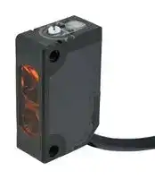


SA2E-DP3M-2M
Photo Sensor, 500 mm, PNP, Diffuse Reflective, 10 to 30 VDC, Cable, SA2E Series
- Manufacturer: IDEC
- Product type:
- SVHC: No SVHC (15-Jan-2019)
- Product Range: SA2E Series
- Sensing Method: Diffuse Reflective
- Connection Method: Cable
- Sensing Range Max: 500mm
- Sensor Output Type: PNP
- Supply Voltage DC Max: 30V
- Supply Voltage DC Min: 10V
| Delivery and price | |
|---|---|
| Units per pack | 50 |
| Price | 25.58 € |
| Current stock | 10+ |
| Lead time | 30 days |
Miniature Photoelectric Sensors - (Built in Amplifier)/Laser Model - SA2E/SA1E/SA1E L ## Miniature High-Performance Photoelectric Sensors Enhanced detection accuracy and response time ## Through-beam **==> picture [111 x 12] intentionally omitted <==** **----- Start of picture text -----**<br> Background Suppression<br>**----- End of picture text -----**<br> ||||||| |---|---|---|---|---|---| ||||||| |Sensing Method|Through-beam||Retro-reflective||| ||||Polarized Retro-reflective||Coaxial Polarized Retro-reflective<br>(Transparent object sensing)| |Part No.|SA2E-T|SA1E-LT|SA2E-P|SA1E-LP|SA1E-X| |Sensing Range|20m|30m|5m<br>(Depends on the reflector)|10m|2m<br>(Depends on the reflector)| |Light Source Element|Red LED|Red laser|Red LED|Red laser|Red LED| |Detectable Object|Opaque(*1)|ø6mm<br>(opaque, at 3m) (*1)|Opaque(*1)|ø6mm opaque<br>(opaque, at 3 m) (*1)|Opaque/Mirror/<br>Transparent(*1)| |Response Time|**0.5**ms|0.25ms|**0.5**ms|0.25ms|**0.5**ms| |Sensitivity Adjustment/<br>Sensing Range<br>Adjustment (BGS only)|Single-turn control (approx. 240°)||||| |Operation Mode|Light ON/Dark ON<br>(select by model)|Light ON/Dark ON (selectable)<br>(select using the Operation Mode Switch)|||Light ON/Dark ON<br>(select by model)| |Control Output|NPN/PNP open collector||||| |Current Draw<br>(Power Voltage 12 to 24V DC)|Projector:20mA maximum<br>Receiver:20mA maximum|Projector:15mA maximum<br>Receiver:30mA maximum|20mA maximum|35mA maximum|20mA maximum| |Degree of Protection|IP67||||| |Operating Temperature<br>(no freezing)|**–30**to**+55**°C|–10 to +55°C|**–30**to**+55**°C|–10 to +55°C|–25 to +55°C| |Dimensions|W10.8× D19.5× H31.5(excluding LEDs and controls)||||| *1: Be sure to check the operation before use. 2 SA2E/SA1E/SA1E-L ## distances, & sensing objects **==> picture [77 x 15] intentionally omitted <==** **----- Start of picture text -----**<br> Diffuse-reflective<br>**----- End of picture text -----**<br> ## Small-beam Reflective Reflective ||||||| |---|---|---|---|---|---| ||||||| |Reflective|||||| |Background Suppression<br>(BGS)||Diffuse-reflective|||Small-beam<br>Reflective| |SA2E-B|SA1E-LB|SA2E-D|||SA2E-N| |10to350mm<br>Adjustable sensing range 20 to 350mm|20to300mm<br>Adjustable sensing range 40 to 300mm|100mm|500mm|1m|50to150mm| |Red LED|Red laser|Infrared LED|Red LED|Infrared LED|Red LED| |Opaque(*1)|ø0.2mm<br>(copper wire, at 170mm) (*1)|Opaque/Transparent(*1)|||Opaque/Transparent(*1)| |**0.5**ms|0.25ms|**0.5**ms|||**0.5**ms| |Approx. 7-turn endless<br>control|6-turn endless control|Single-turn control (approx. 240°)|||| |Light ON/Dark ON (selectable)<br>(select using the Operation Mode Switch)|||||| |NPN open collector or PNP open collector|||||| |20mA maximum|35mA maximum|20mA maximum|||20mA maximum| |IP67|||||| |**–30**to**+55**°C|–10 to +55°C|**–30**to**+55**°C|||**–30**to**+55**°C| |W10.8× D19.5× H31.5(excluding LEDs and controls)|||||| 3 **==> picture [494 x 411] intentionally omitted <==** **----- Start of picture text -----**<br> SA2E SA1E SA1E-L<br>Through-beam 20m<br>SA2E SA1E-L 30m (laser)<br>=1-—__1=<br>Max. 5m<br>Polarized (IAC-R5/R8)<br>Retro-reflective<br>Max. 10m (laser)<br>SA2E SA1E-L (IAC-R5/R8)<br>= Reflector<br>Coaxial Polarized<br>Retro-reflective Max. 2m (IAC-R9)<br>SA1E<br>i Reflector<br>Diffuse reflective 100mm<br>SA2E 500mm<br>Three sensing variations<br>according to distance are 1m<br>available.<br>Background 10 to 350mm<br>Suppression<br>20 to 300mm (laser type)<br>SA2E SA1E-L<br>Small-beam<br>50 to 150mm<br>SA2E<br>≈<br>**----- End of picture text -----**<br> ## SA2E Small objects moving at high speed were detected at intervals, but with SA2E, the response time is 0.5ms, allowing continuous detection of small objects at high speed. 4 SA2E-B Background Suppression (BGS) i By reducing the light beam diameter by 30 to 40% compared to conventional photoelectric sensors, the accuracy of the detecting position is improved. **==> picture [305 x 168] intentionally omitted <==** **----- Start of picture text -----**<br> Conventional SA2E-B<br>product<br>i : ps F<br>oe l<br>ON<br>Wide beam diameter Small beam diameter<br>> Detects the object closer<br>to the optical axis<br>Object Object<br>_ \| (<br>e i fm<br>Sensing point Optical axis<br>(machine axis)<br>**----- End of picture text -----**<br> ## ~~a~~ SA2E SA1E SA1E-L IDEC’s unique air blower unit mounting bracket is available as an option. Maintains detection performance of the sensor and keeps the detection surface clean. Designed to blow air over the entire lens at the optimum pressure **==> picture [178 x 87] intentionally omitted <==** **----- Start of picture text -----**<br> The port can supply air from<br>two directions and can be<br>selected depending on location<br>| E- =<br>**----- End of picture text -----**<br> **==> picture [25 x 6] intentionally omitted <==** **----- Start of picture text -----**<br> SA9Z-A02<br>**----- End of picture text -----**<br> ## SA2E Features operating temperature range of -30 to +55°C. Ideal for installation on equipment used in cold storage warehouses. **==> picture [61 x 70] intentionally omitted <==** **----- Start of picture text -----**<br> Cold storage mobile rack<br>fe ae<br>-30 to<br>+55°C<br>**----- End of picture text -----**<br> ## SA2E a] In addition to reverse-polarity protection for the power voltage, an output reverse-polarity protection circuit is also built-in, to protect the sensor from damage in the event of incorrect wiring. **==> picture [195 x 104] intentionally omitted <==** **----- Start of picture text -----**<br> 12 to 24V DC<br>Example for<br>NPN output +V<br>Load<br>OUT<br>[]<br>100mA max.<br>0V<br>The built-in reverse-polarity protection diode prevents damage even if the<br>wiring is incorrect.<br>Main Circuit<br>**----- End of picture text -----**<br> 5 ## Sensors available to suit a variety of workpieces O—$————ee — ## Background Suppression (BGS) Ignores background and reliably detects workpieces. Not easily affected by the color of the workpiece and edges can be accurately detected by narrow beams. Detailed setting of distances is possible. **==> picture [274 x 60] intentionally omitted <==** **----- Start of picture text -----**<br> SA2E-B Background Suppression (BGS)<br>Diffuse-reflective Background Suppression (BGS)<br>ON ON OFF ON<br>**----- End of picture text -----**<br> ## Coaxial Polarized Retro-reflective (Transparent object sensing) **==> picture [216 x 11] intentionally omitted <==** **----- Start of picture text -----**<br> SA1E-X Coaxial Polarized Retro-reflective Transparent Object Sensing)<br>**----- End of picture text -----**<br> ❚ Detects transparent objects of various shapes Coaxial optical structure and narrow beam ensure stable detection; unaffected by narrowing, inclination or shaking of transparent objects. ## ❚ Application examples of transparent object sensing Because of its coaxial structure, SA1E-X does not have a blind zone, such as shown below. Other than detecting transparent objects, because the workpiece can be detected closely to the sensor, SA1E-X can be used in applications in narrow installation locations and where objects are near the sensor. **==> picture [494 x 208] intentionally omitted <==** **----- Start of picture text -----**<br> (non-coaxial) (coaxial)<br>Sensor Reflector Reflector Sensor Reflector Reflector<br>Blind Zone No blind zone!<br>Mail sorting machine<br>Application examples<br>C—Ory<br>SA2E SA1E<br>Coaxial Polarized Retro-reflective<br>Through-beam Polarized Retro-reflective Diffuse-reflective Background Suppression (BGS) (Transparent Object Sensing)<br>Automated parking garage Detection of mirror surfaces Restroom sink Detecting PC board at Detecting the end of a<br>inspections transparent film<br>様<br>**----- End of picture text -----**<br> 6 ## Laser models ensure fast response and accurate sensing ————_— | SA1E-L ## ❚ Easy-to-align optical axis IDEC’s unique optical lens adjust function achieves easy and speedy optical adjustment when installing machines and equipment. Simple and accurate set up of long distance and small workpiece reading. **==> picture [310 x 93] intentionally omitted <==** **----- Start of picture text -----**<br> SA1E-L IDEC’s unique optical lens adjustment mechanism<br>viewed from Beam irradiation parallel to the mechanical axis of the housing is achieved for easy on-site<br>— the top installation. (Patent pending)<br>Housing<br>Optical lens<br>(position<br>adjustment)<br>Laser Adjustment Parallel to the mechanical axis<br>diode fes t (Bet 7 of the housing<br>**----- End of picture text -----**<br> ## ❚ Detects fast-moving objects The fast 0.25ms response speed allows reliable detection of closely spaced objects on a fastmoving conveyor. **==> picture [45 x 57] intentionally omitted <==** **----- Start of picture text -----**<br> -<br>High speed<br>0 . 25ms<br>IP67<br>**----- End of picture text -----**<br> ## ❚ Dust and water resistant IP67 protection suitable for environments exposed to dust or water vapor. ## ❚ Easy positioning Because the visible red laser is easily seen in both short (20mm) and long (30m) distances, the detecting position and optical axis can be seen at a glance. The small beam can detect small objects, and also enables easy positioning of the sensor in applications where the beam passes through narrow spaces. All models are Class 1 laser compliant (JIS, IEC, FDA). ## Application examples Elly] | SA1E-L **==> picture [267 x 87] intentionally omitted <==** **----- Start of picture text -----**<br> Detection from narrow locations Detection of narrow gaps between Long distance detection<br>objects on high-speed lines<br>Max.<br>**----- End of picture text -----**<br> **==> picture [186 x 7] intentionally omitted <==** **----- Start of picture text -----**<br> Detection in dust or water vapor Detection of small objects<br>**----- End of picture text -----**<br> 7 Miniature Photoelectric Sensors (Built-in Amplifier)/Laser Model See website for details on approvals and standards. ## SA2E/SA1E **==> picture [496 x 631] intentionally omitted <==** **----- Start of picture text -----**<br> Package Quantity: 1<br>Sensing Method Sensing Range Connection [Cable Length ] Operation Mode Part No.<br>(m) NPN Output PNP Output<br>Cable 2 SA2E-TN3-2M SA2E-TP3-2M<br>20m Select<br>Light ON/<br>Dark ON<br>* See the characteristics on P18. Connector — SA2E-TN3C SA2E-TP3C<br>5.0m (50mm)<br>When using IAC-R5/R8<br>3.0m (50mm) Cable 2 SA2E-PN3-2M SA2E-PP3-2M<br>When using IAC-R6<br>2.0m (150mm) Select<br>When using IAC-RS2 Light ON/<br>1.3m (150mm) Dark ON<br>When using IAC-RS1<br> (*1) (*2) 1.6m (100mm) Connector — SA2E-PN3C SA2E-PP3C<br>When using IAC-R7 <br>* See the characteristics on P19.<br>Cable 2 SA2E-DN3L-2M SA2E-DP3L-2M<br>1m<br>* See the characteristics on P19. Connector — SA2E-DN3LC SA2E-DP3LC<br>Cable 2 Select SA2E-DN3M-2M SA2E-DP3M-2M<br>500mm Light ON/<br>* See the characteristics on P19. Connector — Dark ON SA2E-DN3MC SA2E-DP3MC<br>Cable 2 SA2E-DN3S-2M SA2E-DP3S-2M<br>100mm<br>* See the characteristics on P19. Connector — SA2E-DN3SC SA2E-DP3SC<br>Cable 2 SA2E-BN3-2M SA2E-BP3-2M<br>10 to 350mm Select<br>Light ON/<br>Adjustable Sensing Range Dark ON<br>20 to 350mm<br>Connector — SA2E-BN3C SA2E-BP3C<br> * See the characteristics on P20.<br>Cable 2 SA2E-NN3-2M SA2E-NP3-2M<br>Select<br>50 to 150mm Light ON/<br>Dark ON<br>Connector — SA2E-NN3C SA2E-NP3C<br> * See the characteristics on P19.<br>Light ON SA1E-XN1 SA1E-XP1<br>1<br>2.0m Dark ON SA1E-XN2 SA1E-XP2<br>(when using IAC-R9) Light ON SA1E-XN1-2M SA1E-XP1-2M<br>Cable 2<br>1.0m Dark ON SA1E-XN2-2M SA1E-XP2-2M<br>(when using IAC-R10)<br>Light ON SA1E-XN1-5M SA1E-XP1-5M<br>5<br>1.0m Dark ON SA1E-XN2-5M SA1E-XP2-5M<br> (*1) (when using IAC-R11)<br>Connector — Light ON SA1E-XN1C SA1E-XP1C<br> * See the characteristics on P20. Dark ON SA1E-XN2C SA1E-XP2C<br>Red LED<br>Through-beam<br>With Sensitivity Adjustment<br>Red LED<br>Polarized Retro-reflective With Sensitivity Adjustment<br>Infrared LED<br>Red LED<br>Diffuse-reflective<br>With Sensitivity Adjustment<br>Infrared LED<br>Red LED<br>Background Suppression (BGS) With Sensing Range Adjustment<br>Red LED<br>Small-beam Reflective<br>With Sensitivity Adjustment<br>Red LED<br>(Transparent Object Sensing) Coaxial Polarized Retro-reflective With Sensitivity Adjustment<br>**----- End of picture text -----**<br> *1: Maintain at least the distance shown in the ( ) between the photoelectric switch and reflector. - *2: Reflectors are not supplied and must be ordered separately. - Through beam SA2E-T models are engraved with SA2E-T*3P (projector) and SA2E-T*3R (receiver) for identification. 8 Miniature Photoelectric Sensors (Built-in Amplifier)/Laser Model ## SA1E–L **==> picture [496 x 376] intentionally omitted <==** **----- Start of picture text -----**<br> Part No. Package Quantity: 1<br>Part No.<br>Sensing Method Sensing Range Connection Cable Length (m)<br>NPN Output PNP Output<br>1 SA1E-LTN3 SA1E-LTP3<br>30m Cable 2 SA1E-LTN3-2M SA1E-LTP3-2M<br>5 SA1E-LTN3-5M SA1E-LTP3-5M<br>Connector — SA1E-LTN3C SA1E-LTP3C<br> * See the characteristics on P21.<br>1 SA1E-LPN3 SA1E-LPP3<br>10m [300mm] Cable 2 SA1E-LPN3-2M SA1E-LPP3-2M<br>When using IAC-R5/R8<br>10m [300mm]<br>When using IAC-R9<br>5 SA1E-LPN3-5M SA1E-LPP3-5M<br>(*1)<br>Connector — SA1E-LPN3C SA1E-LPP3C<br> * See the characteristics on P21.<br>1 SA1E-LBN3 SA1E-LBP3<br>Cable 2 SA1E-LBN3-2M SA1E-LBP3-2M<br>20 to 300 mm<br>Adjustable Sensing Range 5 SA1E-LBN3-5M SA1E-LBP3-5M<br>40 to 300mm<br>Connector — SA1E-LBN3C SA1E-LBP3C<br> * See the characteristics on P22.<br>Red laser<br>Through-beam<br>w/Sensitivity Adjustment<br>Red laser<br>Polarized Retro-reflective w/Sensitivity Adjustment<br>Red laser<br>Background Suppression (BGS) w/Sensing Range Adjustment<br>**----- End of picture text -----**<br> *1: Maintain at least the distance shown in [ ] between the photoelectric switch and reflector. Reflectors are not supplied and must be ordered separately. 9 Miniature Photoelectric Sensors (Built-in Amplifier)/Laser Model ## SA2E/SA1E ## Specifications **==> picture [496 x 601] intentionally omitted <==** **----- Start of picture text -----**<br> Through-beam Polarized Retro-reflective<br>Part No. SA2E-T SA2E-P <br>Power Voltage 12 to 24V DC (Operating range: 10 to 30V DC) equipped with reverse-polarity protection<br>Projector: 20mA maximum<br>Current Draw 20mA maximum<br>Receiver: 20mA maximum<br>5.0 m (IAC-R5/R8)<br>3.0 m (IAC-R6)<br>2.0 m (IAC-RS2)<br>Sensing Range 20m<br>1.3 m (IAC-RS1)<br>1.6 m (IAC-R7 )<br>(*1)<br>—<br>Adjustable Sensing Range<br>Detectable Object Opaque (*2)<br>Hysteresis — 20% maximum<br>Response Time 0.5ms maximum 0.5 ms maximum<br>Sensitivity Adjustment Single-turn control (approx. 240°)<br>—<br>Sensing Range Adjustment<br>Light Source Element Red LED Red LED<br>Operation Mode Light ON/Dark ON (select using the Operation Mode Switch)<br>NPN open collector or PNP open collector (30V DC, 100 mA maximum with short circuit protection circuit)<br>Voltage drop:<br>Control Output 2V max. (30V DC, 100mA)<br>1.2V max. (30V DC, 10mA)<br>Output Reverse-polarity Protection Circuit<br>Operation LED: Amber<br>LED Indicators<br>Stable LED: Green, Power LED: Green (Through-beam type projector)<br>Interference Prevention — Two units can be mounted in close proximity.<br>Degree of Protection IP67 (IEC60529)<br>Extraneous Light Immunity Sunlight: 40,000 lux maximum, Incandescent lamp: 10,000 lux maximum (at receiver)<br>Operating Temperature -30 to +55°C (no freezing)<br>Operating Humidity 35 to 95% RH (no condensation)<br>Storage Temperature -40 to +70°C (no freezing)<br>Insulation Resistance Between live part and mounting bracket: 20 MΩ minimum (500V DC megger)<br>Dielectric Strength 1,000V AC, 50/60 Hz, 1 minute (between live part and mounting bracket)<br>10 to 55 Hz, amplitude 1.5mm<br>55 to 500 Hz, acceleration 90m/s [2]<br>Vibration Resistance<br>1 cycle 5 mins<br>30 mins in each of 3 axes<br>1000m/s [2]<br>Shock Resistance<br>3 shocks in 6 directions on 3 axes<br>Case PBT<br>Material Lens PMMA<br>Indicator Model PC<br>Weight Cable Type Projector: 50g, Receiver: 50g (*3) 50g<br>(approx.) Connector Type Projector: 10g, Receiver: 10g 20g<br>Connection Cable Type ø3.5mm, 3-core (2-core for through-beam), 0.2mm [2] , vinyl cabtyre cable<br>Method Connector Type M8 connector (4-pin)<br>**----- End of picture text -----**<br> - *1: Maintain at least the distance shown below between the photoelectric switch and reflector. IAC-R5/R6/R8: 50mm, IAC-R7: 100mm, IAC-RS1/RS2: 150mm - The detection distance cannot be guaranteed if the reflector is deformed or the reflector tape is applied on an uneven surface. - *2: Be sure to check the operation before use. - *3: Cable length: 2m (30g when the cable length is 1m. 110g when the cable length is 5m.) 10 Miniature Photoelectric Sensors (Built-in Amplifier)/Laser Model ## SA2E/SA1E ## Specifications **==> picture [496 x 623] intentionally omitted <==** **----- Start of picture text -----**<br> Diffuse-reflective Coaxial Polarized<br>Background Suppression<br>Small-beam Reflective Retro-reflective<br>Short Distance Medium Distance Long Distance (BGS)<br>(Transparent Object Sensing)<br>Part No. SA2E-D 3S SA2E-D 3M SA2E-D 3L SA2E-B SA2E-N SA1E-X <br>Power Voltage 12 to 24V DC (Operating range: 10 to 30V DC) equipped with reverse-polarity protection<br>Current Draw 20mA maximum<br>100mm 500mm 1m<br>10 to 350mm 50 to 150mm<br>( using 200 × ( using 200 × ( using 200 × 2m<br>Sensing Range ( using 200 × 200mm ( using 100 × 100mm<br>200mm white 200mm white 200mm white (using IAC-R9)<br>white paper) white paper)<br>paper) paper) paper)<br>20 to 350mm<br>— —<br>Adjustable Sensing Range ( using 200 × 200mm<br>white paper)<br>Opaque/transparent/mirror<br>Detectable Object Opaque/transparent (*1) Opaque (*1) Opaque/transparent (*1)<br>(*1)<br>Hysteresis 20% maximum 5% maximum 20% maximum —<br>Response Time 0.5ms maximum<br>Sensitivity Adjustment Adjustable using a control (approx. 240°) — Adjustable using a control (approx. 240°)<br>— Approx. 7-turn endless —<br>Sensing Range Adjustment<br>control<br>Light Source Element Infrared LED Red LED Infrared LED Red LED<br>Light ON/Dark ON (selectable) Light ON/Dark ON<br>Operation Mode<br>(select with the Operation Mode Switch) (select by Part No.)<br>NPN open collector or PNP open collector (30V DC, 100mA maximum with short circuit protection circuit)<br>Voltage drop:<br>Control Output 2V max. (30V DC, 100mA) Voltage drop: 2V max.<br>1.2V max. (30V DC, 10mA) (30V DC, 100mA)<br>Output Reverse-polarity Protection Circuit<br>Operation LED: Amber<br>LED Indicators Operation LED: Yellow<br>Stable LED: Green<br>Interference Prevention Two units can be mounted in close proximity.<br>Degree of Protection IP67 (IEC60529)<br>Sunlight: 10,000 lux<br>maximum, Incandescent<br>Extraneous Light Immunity Sunlight: 40,000 lux maximum, Incandescent lamp: 10,000 lux maximum (at receiver)<br>lamp: 5,000 lux maximum<br>(at receiver)<br>-25 to +55°C<br>Operating Temperature -30 to +55°C (no freezing)<br>(no freezing)<br>Operating Humidity 35 to 95% RH (no condensation)<br>Storage Temperature -40 to +70°C (no freezing)<br>Insulation Resistance Between live part and mounting bracket: 20 MΩ minimum (500V DC megger)<br>Dielectric Strength 1,000V AC, 50/60 Hz, 1 minute (between live part and mounting bracket)<br>10 to 55 Hz, amplitude 1.5mm 10 to 55 Hz,<br>55 to 500 Hz, acceleration 90m/s [2] amplitude 1.5mm<br>Vibration Resistance<br>1 cycle 5 mins 1 cycle 5 mins<br>30 mins in each of 3 axes 30 mins in each of 3 axes<br>500m/s [2]<br>1000m/s [2]<br>Shock Resistance 3 shocks in 6 directions on<br>3 shocks in 6 directions on 3 axes<br>3 axes<br>Case PBT PC/PBT<br>Material Lens PMMA<br>Indicator Model PC<br>Weight Cable Type 50g 55g (*2)<br>(approx.) Connector Type 20g 20g<br>Connection Cable Type ø3.5mm, 3-core, 0.2mm [2] , vinyl cabtyre cable<br>Method Connector Type M8 connector (4-pin)<br>**----- End of picture text -----**<br> - *1: Be sure to check the operation before use. - *2: Cable length: 2m (35g when the cable length is 1m. 120g when the cable length is 5m.) 11 Miniature Photoelectric Sensors (Built-in Amplifier)/Laser Model ## SA1E–L ## Specifications **==> picture [495 x 444] intentionally omitted <==** **----- Start of picture text -----**<br> Through-beam Polarized Retro-reflective Background Suppression (BGS)<br>Part No. SA1E-LT SA1E-LP SA1E-LB <br>Power Voltage 12 to 24V DC (Operating range: 10 to 30V DC) equipped with reverse-polarity protection<br>Projector: 15mA maximum<br>Current Draw 35mA maximum<br>Receiver: 30mA maximum<br>20 to 300mm (using 100 × 100mm<br>Sensing Range 30m 0.3 to 10m (using IAC-R5/R8/R9)<br>white paper)<br>Adjustable Sensing Range — 40 to 300mm<br>Detectable Object Size (typical) ø6mm minimum (opaque, at 3m) ø0.2mm minimum (copper wire, at 170mm)<br>Detectable Object Opaque ( [*] 1)<br>Hysteresis — 10% maximum<br>Response Time 0.25ms maximum<br>Sensitivity Adjustment Adjustable using a control —<br>Sensing Range Adjustment — 6-turn control knob<br>Light Source Element Red laser diode (emission wavelength: 650nm) (IEC/JIS/FDA Class 1) ( [*] 2)<br>Light ON/Dark ON (selectable)<br>Operation Mode<br>(select with the Operation Mode Switch)<br>NPN open collector or PNP open collector (30V DC, 100mA maximum with short circuit protection circuit)<br>Control Output<br>Voltage drop: 1.5V max.<br>Operation LED: Yellow<br>LED Indicators<br>Stable LED: Green, Power LED: Green (Through-beam type projector only)<br>Interference Prevention — Two units can be mounted in close proximity.<br>Degree of Protection IP67 (IEC60529)<br>Extraneous Light Immunity Sunlight: 10,000 lux maximum, Incandescent lamp: 5,000 lux maximum (at receiver)<br>Operating Temperature -10 to +55°C (no freezing)<br>Operating Humidity 35 to 85% RH (no condensation)<br>Storage Temperature -25 to +70°C (no freezing)<br>Storage Humidity 35 to 85% RH (no condensation)<br>Insulation Resistance Between live part and mounting bracket: 20 MΩ minimum (500V DC megger)<br>Cable types: 1,000V AC, 50/60 Hz, 1 minute (between live part and mounting bracket)<br>Dielectric Strength<br>Connector types when connected with connector cable: 500V AC, 50/60 Hz, 1 minute (between live part and clamp ring)<br>10 to 55 Hz, amplitude 1.5mm<br>Vibration Resistance 1 cycle 5 mins<br>30 mins in each of 3 axes<br>500m/s [2]<br>Shock Resistance<br>3 shocks in 6 directions on 3 axes<br>Material Housing: PBT, Lens: PMMA, Indicator cover: PC, knob: POM<br>Weight Cable Type 35g ( [*] 3)<br>(approx.) Connector Type 20g<br>Connection Cable Type ø3.5mm, 3-core, 0.2mm [2] , vinyl cabtyre cable<br>Method Connector Type M8 connector (4-pin)<br>**----- End of picture text -----**<br> - *1: Be sure to check the operation before use. - *2: Compliant with Class 1 of FDA regulations (21 CFR 1040.10 and 21 CFR 1040.11 according to Laser Notice No. 50). - *3: Cable length: 1m (55g when the cable length is 2m. 120g when the cable length is 5m.) 12 Miniature Photoelectric Sensors (Built-in Amplifier)/Laser Model ## SA2E/SA1E/SA1E–L ## Slit and Sensing Range (typical) [Through-beam SA2E-T ] |Slit|Slit|With SensitivityAdjustment|With SensitivityAdjustment|With SensitivityAdjustment|With SensitivityAdjustment| |---|---|---|---|---|---| |||SensingRange(m)||Minimum Detectable Object Width(mm) (*1)|| |Part No.|Slit Width: A (SeeP26.)|Attached on:<br>Receiver|Attached on:<br>Receiver/Projector|Attached on:<br>Receiver|Attached on:<br>Receiver/Projector| |SA9Z-S06|0.5mm|2.5|1.0|0.5|0.5| |SA9Z-S07|1.0mm|3.5|1.5|1.0|1.0| |SA9Z-S08|2.0mm|6.0|3.5|2.0|2.0| |SA9Z-S09|0.5mm|2.0|0.7|0.5|0.5| |SA9Z-S10|1.0mm|3.0|1.5|1.0|1.0| |SA9Z-S11|2.0mm|5.5|3.0|2.0|2.0| |SA9Z-S12|0.5mm|0.8|0.08|0.5|0.5| |SA9Z-S13|1.0mm|1.5|0.3|1.0|1.0| |SA9Z-S14|2.0mm|2.5|1.2|2.0|2.0| - *1: At 1mm from receiver surface. - The slit can be snapped onto the front easily. (See the figure below.) - To order, see Ordering Part No. on page 23. **==> picture [32 x 17] intentionally omitted <==** **----- Start of picture text -----**<br> Slit<br>(Stainless)<br>**----- End of picture text -----**<br> Horizontal slits and round slits have an orientation. Make sure that the TOP marking comes on top of the sensor (LED side). ## Slit and Sensing Range (typical) [Through-beam SA1E-LT ] |Slit|Slit|SensingRange(m)|Minimum Detectable Object Width(mm)| |---|---|---|---| |Part No.|Slit Width: A|Used on receiver|Used on receiver| |SA9Z-S12|0.5mm|6|1.1| |SA9Z-S13|1.0mm|10|1.6| |SA9Z-S14|2.0mm|22|2.5| **==> picture [112 x 127] intentionally omitted <==** **----- Start of picture text -----**<br> The slit can be snapped onto<br>the front easily.<br>Slit<br>(Stainless)<br>The slits have an orientation. Make<br>sure that the TOP marking comes on<br>top of the sensor (LED side).<br>**----- End of picture text -----**<br> - When slit is mounted only on the receiver (when mounting on one side). - Minimum detectable object width (mm): when the object is at the intermediate point between the projector and receiver. ## Dimensions All dimensions in mm **==> picture [79 x 87] intentionally omitted <==** **----- Start of picture text -----**<br> 8.2 6.1<br>Material: Stainless Steel<br>4.4 øA<br>32.1<br>0.3<br>**----- End of picture text -----**<br> 13 Miniature Photoelectric Sensors (Built-in Amplifier)/Laser Model ## SA2E/SA1E/SA1E–L ## Output Circuit & Wiring Diagram SA2E Through-beam, Polarized Retro-reflective, Diffuse-reflective, Background Suppression (BGS), Small-beam Reflective NPN Output **==> picture [128 x 94] intentionally omitted <==** **----- Start of picture text -----**<br> Brown (1)<br>+V<br>Load<br>Black (4)<br>OUT 12V to<br>Blue (3) 24V DC<br>0V<br>Connector Pin Assignment<br>➃ (OUT) ➂ (0V)<br>➁ (NC) ➀ (+V)<br>Main Circuit<br>**----- End of picture text -----**<br> PNP Output **==> picture [128 x 94] intentionally omitted <==** **----- Start of picture text -----**<br> Brown (1)<br>+V 12V to<br>Black (4) 24V DC<br>OUT<br>Load<br>Blue (3)<br>0V<br>Connector Pin Assignment<br>➃ (OUT) ➂ (0V)<br>➁ (NC) ➀ (+V)<br>Main Circuit<br>**----- End of picture text -----**<br> Through-beam Projector **==> picture [115 x 94] intentionally omitted <==** **----- Start of picture text -----**<br> Brown (1)<br>+V<br>12V to<br>24V DC<br>Blue (3)<br>0V<br>Connector Pin Assignment<br>➃ (NC) ➂ (0V)<br>➁ (NC) ➀ (+V)<br>Main Circuit<br>**----- End of picture text -----**<br> SA1E–X Coaxial Polarized Retro-reflective (Transparent Object Sensing) ## NPN Output **==> picture [130 x 255] intentionally omitted <==** **----- Start of picture text -----**<br> Brown (1)<br>+V<br>Load<br>Black (4)<br>OUT 12V to<br>Blue (3) 24V DC<br>0V<br>Connector Pin Assignment<br>➃ (OUT) ➂ (0V)<br>➁ (NC) ➀ (+V)<br>SA1E–L<br>NPN Output<br>Brown (1)<br>+V<br>Load<br>Black (4)<br>OUT 12V to<br>Blue (3) 24V DC<br>0V<br>Connector Pin Assignment<br>➃ (OUT) ➂ (0V)<br>➁ (NC) ➀ (+V)<br>Main Circuit<br>Main Circuit<br>**----- End of picture text -----**<br> PNP Output **==> picture [128 x 94] intentionally omitted <==** **----- Start of picture text -----**<br> Brown (1)<br>+V 12V to<br>Black (4) 24V DC<br>OUT<br>Blue (3) [Load]<br>0V<br>Connector Pin Assignment<br>➃ (OUT) ➂ (0V)<br>➁ (NC) ➀ (+V)<br>Main Circuit<br>**----- End of picture text -----**<br> **==> picture [308 x 116] intentionally omitted <==** **----- Start of picture text -----**<br> PNP Output Through-beam Projector<br>Brown (1) Brown (1)<br>+V 12V to +V<br>Black (4) 24V DC<br>12V to<br>OUTBlue (3) [Load] 24V DC<br>0V<br>Blue (3)<br>Connector Pin Assignment 0V Connector Pin Assignment<br>➃ (OUT) ➂ (0V) ➃ (NC) ➂ (0V)<br>➁ (NC) ➀ (+V) ➁ (NC) ➀ (+V)<br>Main Circuit<br>Main Circuit<br>**----- End of picture text -----**<br> PNP Output 14 Miniature Photoelectric Sensors (Built-in Amplifier)/Laser Model ## Dimensions (SA2E/SA1E) All dimensions in mm. ## Cable Type Through-beam (SA2E-T) Polarized Retro-reflective (SA2E-P) Diffuse-reflective (SA2E-D) Background Suppression (BGS) (SA2E-B) Small-beam Reflective (SA2E-N) - *1: LED power indicator (green) for SA2E-T through-beam. - *2: The SA2E-T through-beam does not have a sensitivity control, operation mode switch, or stable LED. - *3: SA2E-B has a knob for setting sensing range (7-turn endless control). **==> picture [495 x 265] intentionally omitted <==** **----- Start of picture text -----**<br> 11.8 Operation LED (amber) (*1)<br>8.2<br>Sensitivity Control (*2) (*3)<br>ReceiverProjector Receiver (movable) Stable LED (green) (*2) (L: Light ON/D: Dark ON)Operation Mode Switch<br>0.1<br>Projector 19.5<br>2-M3<br>7.4 Projector 7.8 Projector 7.4 3.4<br>Through-beam (SA2E-T) Background Suppression Polarized Retro-reflective (SA2E-P)<br>(BGS) (SA2E-B) Diffuse-reflective (SA2E-D)<br>Small-beam Reflective (SA2E-N)<br>3.2<br>10.8<br>1.2<br>19.2 19.8 19.2 9.9 31.5 25.4<br>20.2<br>17.1<br>7.2 7.2<br>(3.1) (3.1) (3.1) (3.1) (3.1)<br>**----- End of picture text -----**<br> Coaxial Polarized Retro-reflective (Transparent Object Sensing) (SA1E-X) **==> picture [224 x 211] intentionally omitted <==** **----- Start of picture text -----**<br> 14.5<br>11.0<br>19.5<br>3.4<br>Projector/<br>Receiver<br>(coaxial)<br>2-M3<br>ø5.2<br>ø3.5<br>2.9<br>10.8<br>0.9<br>31.5 25.4<br>4.5 17.2<br>**----- End of picture text -----**<br> 15 Miniature Photoelectric Sensors (Built-in Amplifier)/Laser Model All dimensions in mm. ## Dimensions (SA2E/SA1E) ## Connector Type Through-beam (SA2E-T) Polarized Retro-reflective (SA2E-P) Diffuse-reflective (SA2E-D) Background Suppression (BGS) (SA2E-B) Small-beam Reflective (SA2E-N) - *1: LED power indicator (green) for SA2E-T through-beam. - *2: The SA2E-T through-beam does not have a sensitivity control, operation mode switch, or stable LED. - *3: SA2E-B has a knob for setting sensing range (7-turn endless control). **==> picture [492 x 271] intentionally omitted <==** **----- Start of picture text -----**<br> 11.8 Operation LED (amber) (*1)<br>8.2<br> (*1)<br>Sensitivity Control (*2) (*3) Operation Mode Switch<br>Projector Stable LED (green) (*2) (L: Light ON/D: Dark ON)<br>Receiver<br>Receiver (movable) Receiver 19.5 0.1<br>7.4 Projector 7.8 Projector 7.4 3.4 2-M3<br>Through-beam (SA2E-T) Background Suppression Polarized Retro-reflective (SA2E-P)<br>(BGS) (SA2E-B) Diffuse-reflective (SA2E-D)<br>Small-beam Reflective (SA2E-N)<br>3.2<br>10.8<br>1.2<br>19.2 19.8 19.2 9.9 31.5 25.4<br>20.2<br>17.1<br>7.2 7.2 (3.1)<br>)(3.1 )(3.1 )(3.1 10.8 (13.9)<br>**----- End of picture text -----**<br> **==> picture [334 x 212] intentionally omitted <==** **----- Start of picture text -----**<br> 14.5<br>11.0<br>19.5<br>3.4<br>Projector/<br>Receiver<br>(coaxial)<br>2-M3<br>*1: The connector length is 18 mm when a<br>(*1) M8 right-angle connector cable<br>(SA9Z-CM8K-4L ) is attached.<br>ø5.2<br>2.9<br>10.8<br>0.9<br>31.5 25.4<br>4.5 17.2<br>4.5<br>6.3<br>**----- End of picture text -----**<br> Coaxial Polarized Retro-reflective (Transparent Object Sensing) (SA1E-X) 16 Miniature Photoelectric Sensors (Built-in Amplifier)/Laser Model ## Dimensions (SA1E–L) **==> picture [62 x 7] intentionally omitted <==** **----- Start of picture text -----**<br> All dimensions in mm.<br>**----- End of picture text -----**<br> **==> picture [433 x 257] intentionally omitted <==** **----- Start of picture text -----**<br> Cable Type<br>Through-beam Polarized retro-reflective 15.3 Operation LED (yellow) (*2)<br>11.8<br>Operation Mode Switch (*1)<br>Background suppression (BGS) 8.2<br>Operation LED (green) (*1)<br>Sensitivity Control (except BGS) (*1)<br>Sensing Range Control (BGS)<br>19.5<br>Projector Receiver<br>Receiver<br>(*3)<br>Projector<br>2-M3 3.4<br>7.8<br>Through-beam (SA1E-LT) Polarized retro-reflective (SA1E-LP)<br>Background suppression (BGS) (SA1E-LB)<br>ø3.5<br>3.2<br>10.8<br>1.2<br>19.8 8.0 31.5 25.4<br>17.1<br>7.2<br>**----- End of picture text -----**<br> **==> picture [434 x 274] intentionally omitted <==** **----- Start of picture text -----**<br> Connector Type<br>Through-beam Polarized retro-reflective 15.3 Operation LED (yellow) (*2)<br>11.8<br>Background suppression (BGS) 8.2 Operation Mode Switch (*1)<br>Operation LED (green) (*1)<br>Sensitivity Control (except BGS) (*1)<br>Sensing Range Control (BGS)<br>19.5<br>Projector Receiver<br>Receiver<br>Projector 4.5 2-M3<br>(*4) M8×1<br>7.8 3.4<br>Through-beam (SA1E-LT) Polarized retro-reflective (SA1E-LP)<br>Background suppression (BGS) (SA1E-LB)<br>3.2<br>10.8<br>1.2<br>19.8 8.0 31.5 25.4<br>17.1<br>7.2<br>6.3<br>**----- End of picture text -----**<br> - *1: No stable LED, sensitivity control, and operation mode switch are attached on the through-beam projector. - *2: Power LED (green) for through-beam projector. - *3: Cable length depends on models. - *4: The connector length is 18mm when a right-angle connector cable (SA9Z-CM8K-4L ) is attached. 17 Miniature Photoelectric Sensors (Built-in Amplifier)/Laser Model ## Characteristics (Typical) (SA2E) ## (1) Through-beam SA2E-T **==> picture [496 x 684] intentionally omitted <==** **----- Start of picture text -----**<br> Excess Gain vs. Sensing Distance (Without slit) Lateral Displacement (Without slit) Angle (Without slit)<br>100 500 100<br>400 80<br>300 60<br>200 Y 40<br>100 20<br>10 0 X 0<br>-100 -20<br>-200 -40 ø<br>-300 -60 X<br>-400 -80<br>Operation 1 -500 -100<br>Level 0 5 10 15 20 25 30 0 5 10 15 20 25 30 0 5 10 15 20 25 30<br>Sensing Distance (m) Sensing Distance X (m) Sensing Distance X (m)<br>Excess Gain vs. Sensing Distance (With vertical slit) Excess Gain vs. Sensing Distance (With horizontal slit) Excess Gain vs. Sensing Distance (With round slit)<br>100 100 100<br>10 10 10<br>Operation 1 Operation 1 Operation 1<br>Level 0 2 4 6 8 10 12 Level 0 2 4 6 8 10 12 Level 0 2 4 6 8 10 12<br>Sensing Distance (m) Sensing Distance (m) Sensing Distance (m)<br>Lateral Displacement (With 0.5-mm vertical slit) Lateral Displacement (With 1.0-mm vertical slit) Lateral Displacement (With 2.0-mm vertical slit)<br>120 Y 140 200<br>100 120<br>80 X 100 150<br>80<br>60 60 100<br>4020 4020 Y 50 Y<br>-20-400 -20-400 X -500 X<br>-60<br>-60 -80 -100<br>-80 -100 -150<br>-100 -120<br>-120 -140 -200<br>0 1 2 3 4 5 6 7 0 1 2 3 4 5 6 7 8 9 10 0 2 4 6 8 10 12<br>Sensing Distance X (m) Sensing Distance X (m) Sensing Distance X (m)<br>Lateral Displacement (With 0.5-mm horizontal slit) Lateral Displacement (With 1.0-mm horizontal slit) Lateral Displacement (With 2.0-mm horizontal slit)<br>120 200 Y 250<br>10080 150 X 200150<br>60 100<br>40 100<br>20 50 50 Y<br>0 0 0<br>-20 -50 -50 X<br>-40 Y -100<br>-60 -100<br>-80 X -150<br>-100 -150 -200<br>-120 -200 -250<br>0 1 2 3 4 5 6 7 0 1 2 3 4 5 6 7 8 9 10 0 2 4 6 8 10 12<br>Sensing Distance X (m) Sensing Distance X (m) Sensing Distance X (m)<br>Lateral Displacement (With ø0.5-mm round slit) Lateral Displacement (With ø1.0-mm round slit) Lateral Displacement (With ø2.0-mm round slit)<br>40 60 100<br>30 50 80<br>40 60<br>20 30<br>20 40<br>10 Y 10 20 Y<br>0 0 Y 0<br>-10 X -10 -20 X<br>-20 X -40<br>-20 -30<br>-40 -60<br>-30 -50 -80<br>-40 -60 -100<br>0 0.2 0.4 0.6 0.8 1.0 1.2 1.4 1.6 1.8 2.0 0 0.5 1.0 1.5 2.0 2.5 3.0 3.5 4.0 0 1 2 3 4 5 6<br>Sensing Distance X (m) Sensing Distance X (m) Sensing Distance X (m)<br> (°)<br>Excess Gain θ<br>Receiver Angle<br>Lateral Displacement Y (mm)<br>Excess Gain Excess Gain Excess Gain<br>Lateral Displacement Y (mm) Lateral Displacement Y (mm) Lateral Displacement Y (mm)<br>Lateral Displacement Y (mm) Lateral Displacement Y (mm) Lateral Displacement Y (mm)<br>Lateral Displacement Y (mm) Lateral Displacement Y (mm) Lateral Displacement Y (mm)<br>**----- End of picture text -----**<br> 18 Miniature Photoelectric Sensors (Built-in Amplifier)/Laser Model ## Characteristics (Typical) (SA2E) ## (2) Polarized Retro-reflective SA2E-P **==> picture [482 x 679] intentionally omitted <==** **----- Start of picture text -----**<br> Excess Gain vs. Sensing Distance Operating Area Angle<br>100 200 80<br>150 60<br>10 SSSBSSS5555S ||) 100500 Gb IAC-RS1 ask)SS IAC-RS2 IAC-R7 IAC-R6 IAC-R8 IAC-R5 | 40200 e IAC-RS1IAC-R7 ee IAC-RS2IAC-R6 IAC-R8 IAC-R5<br>-50 -20<br>PRSSSS<br>IAC-R7 -100 Y -40 θ<br>IAC-RS2 IAC-R5 -150 -60<br>OperationLevel 1 0 P IAC-RS11 aaSN 2 3 4IAC-R6 TONY 5 oN 6IAC-R8 7 5 8 I 9 -2000 SrBe 1 X 2 3 PEt 4 5 6 Tt 7 ft 8 9 -80 0 Oper ee PT 1 ET 2 3 tT 4 t 5 6 te 7 X 8 9<br>Sensing Distance (m) Sensing Distance X (m) Sensing Distance X (m)<br>(3) Diffuse-reflective SA2E-DS (100mm)<br>Excess Gain vs. Sensing Distance Operating Area Sensing Distance vs. Object Size<br>100 6 YObject: 300<br>X 200 × 200 mm<br>==—====—=— 4 || white mat paper 250 PLT Ey ET TT<br>2 200<br>ae oN eT<br>10 0 150<br>-2 100<br>Sa -4 Nee PT =<br>Pe Pe el 50 Object: Side length A,<br>OperationLevel 1 0 PTET 20 40 60 TTT 80 100 120 Ete 140 160 180 200 -6 0 FIT 20 40 TET TLE 60 80 100 120 140 160 | 180 200 0 0 Pitt 20 40 60 80 white paper100 120 140 160 180 200<br>Sensing Distance (mm) Sensing Distance X (mm) Side Length A (mm)<br>(4) Diffuse-reflective SA2E-DM (500mm)<br>Excess Gain vs. Sensing Distance Operating Area Sensing Distance vs. Object Size<br>100 50 1200<br>40<br>SSS SS 30 po | 1000 || | ERECT<br>20<br>800<br>po 10 — ea o0/000000<br>10 Be 0 anee B K 600 C<br>-10<br>-20 400<br>-30 Y<br>Object: 200 Object: Side length A<br>a -40 “ L X i 200 × 200 mm =e white paper<br>Operation 1 Po A -50 white paper a 0 Pit<br>Level 0 200 400 600 800 1000 1200 0 200 400 600 800 1000 1200 0 20 40 60 80 100 120 140 160 180 200<br>Sensing Distance (mm) Sensing Distance X (mm) Side Length A (mm)<br>(5) Diffuse-reflective SA2E-DL (1m)<br>Excess Gain vs. Sensing Distance Operating Area Sensing Distance<br>100 120 2000<br>100 1800<br>=== 80 a 1600 Fool ean<br>60<br>1400<br>40<br>20 1200<br>10 PEEREEEEEAEERE | 0 EERE) a a 1000 ESHOA EeEe<br>-20 800<br>=== —Sa a -40 ON 600 c of<br>-60 Y<br>PEER RNSEEES -80 +e eee eepne Object: nnee ONT 400 H S Object: Side length A<br>a -100 “ L X i 200 × 200 mm Hy 200 PCr white paper<br>OperationLevel 10 PP 200 400 600 800 1000 1200 1400 AKA 1600 1800 2000 -1200 200 400 600 800white paper1000 1200 1400 1600 a 1800 2000 00 Pero 20 40 60 80 100 120 140 160 180 200<br>Sensing Distance (mm) Sensing Distance X (mm) Side Length A (mm)<br>(6) Small-beam Reflective SA2E-N <br>Excess Gain vs. Sensing Distance Operating Area Sensing Area vs. Object Size<br>100 10 350<br>8 300<br>—— 6 Po re<br>=——— 4 a 250 ane<br>2 200<br>10 | | | | | | 0 reVS ee 150 PoT | oo<br>[———— -2 IN<br>-4 tN 100 ee A<br>OperationLevel 1 0 —————PN 50 100 150 200 250 300 -10-6-80 ee 50 X 100Y Object: 100 × 100mm white paper150 ee 200 ae 250 i 300 500 | 0 pt | 20 40Object: Side length A white paper X 60 80 | _ 100<br>Sensing Distance (mm) Sensing Distance X (mm) Side Length A (mm)<br> (°)<br>θ<br>Excess Gain<br> Reflector Angle<br>Lateral Displacement Y (mm)<br>Excess Gain<br>Lateral Displacement Y (mm) Sensing Distance X (mm)<br>Excess Gain<br>Sensing Distance X (mm)<br>Lateral Displacement Y (mm)<br>Excess Gain<br>Sensing Distance X (mm)<br>Lateral Displacement Y (mm)<br>Excess Gain<br>Sensing Distance X (mm)<br>Lateral Displacement Y (mm)<br>**----- End of picture text -----**<br> 19 Miniature Photoelectric Sensors (Built-in Amplifier)/Laser Model ## Characteristics (SA2E/SA1E) ## (7) Background Suppression (BGS) SA2E-B **==> picture [495 x 680] intentionally omitted <==** **----- Start of picture text -----**<br> Operating Area (Preset 100 mm) Operating Area (Preset 200 mm) Operating Area (Preset 350 mm)<br>6 5 10<br>5 White Paper 4 8<br>4<br>3 3 White 6 White<br>2 Black Paper 2 Paper 4 Paper<br>1 1 BlackPaper 2 Black<br>0 0 0 Paper<br>-1 -1 -2<br>-2<br>-2 -4<br>-3<br>-4 Y Object: 200 × 200mm paper -3 Y Object: 200 × 200mm paper -6 Y Object: 200 × 200mm paper<br>-5 X Distance setting: white paper used -4 X Distance setting: white paper used -8 X Distance setting: white paper used<br>-6 -5 -10<br>0 10 20 30 40 50 60 70 80 90 100 0 20 40 60 80 100 120 140 160 180 200 0 50 100 150 200 250 300 350<br>Sensing Distance (mm) Sensing Distance (mm) Sensing Distance (mm)<br>Light Beam Diameter vs. Sensing Distance Hysteresis vs. Sensing Distance Sensing Distance vs. Control (turns)<br>14 5 600<br>White<br>4.5 Black<br>12 4 Paper 500 Paper<br>10 3.5<br>400<br>8 3<br>6 2.52 GrayPaper 300 GrayPaper<br>4 1.51 WhitePaper 200 Black<br>2 100 Paper<br>0.5<br>0 0 0<br>0 50 100 150 200 250 300 350 0 50 100 150 200 250 300 350 0 1 2 3 4 5 6 7<br>Distance (mm) Sensing Distance (mm) Control (turns)<br>Color (200×200mm paper), material vs. Sensing Distance Color (200×200mm paper), material vs. Sensing Distance Color (200×200mm paper), material vs. Sensing Distance<br>(Preset 100mm) (Preset 200mm) (Preset 350mm)<br>100 200 350<br>90 180<br>300<br>80 160<br>70 140 250<br>60 120 200<br>50 100<br>40 80 150<br>30 60 100<br>20 40<br>50<br>10 20<br>0 0 0<br>(8) Coaxial Polarized Retro-reflective (Transparent Object Sensing) (SA1E-X )<br>Excess Gain vs. Sensing Distance Operating Area Angle<br>100 30 Y 40 θ<br>X 30 X<br>20<br>10 IACI A- R10C-R10IAC形I A- R11C-R11形 IACI A- R9C-R9形 2010 IACI A- R10C-R10形 IACI A- R11C-R11形IACI A- R9C-R9形<br>10 0 0<br>-10<br>-10<br>-20<br>IACI A- R10C-R10形 IACI A- R9C-R9形 -20<br>IACI A- R11C-R11形 -30<br>1 -30 -40<br>0 0.5 1 1.5 2 2.5 3 3.5 4 0 0.5 1 1.5 2 2.5 3 3.5 4 0 0.5 1 1.5 2 2.5 3 3.5 4<br>Sensing Distance X (m) Sensing Distance X (m) Sensing Distance X (m)<br>Light Beam Diameter vs. Distance<br>40<br>35<br>30<br>25<br>20<br>15<br>10<br>5<br>0<br>0 0.2 0.4 0.6 0.8 1 1.2 1.4 1.6 1.8 2<br>Distance (m)<br>Lateral Displacement Y (mm) Lateral Displacement Y (mm) Lateral Displacement Y (mm)<br>Hysteresis (%)<br>Sensing Distance (mm)<br>Light Beam Diameter (mm)<br>Sensing Distance (mm) White Red Green Blue Gray Black Cardboard Aluminum Stainless Steel Brass Plywood Sensing Distance (mm) White Red Green Blue Gray Black Cardboard Aluminum Stainless Steel Brass Plywood Sensing Distance (mm) White Red Green Blue Gray Black Cardboard Aluminum Stainless Steel Brass Plywood<br> (°)<br>Excess Gain θ<br>Reflector Angle<br>Operating Area Y (mm)<br>Light Beam Diameter ø (mm)<br>**----- End of picture text -----**<br> 20 Miniature Photoelectric Sensors (Built-in Amplifier)/Laser Model ## Characteristics (Typical) (SA1E–L) ## (1) Through-beam SA1E-LT **==> picture [477 x 279] intentionally omitted <==** **----- Start of picture text -----**<br> Excess Gain (Without slit) Excess Gain (With slit) Lateral Displacement (Without slit)<br>100 100 30<br>SSS SSS 20 EEEEEEDE=<br>ø2.0<br>ac | One slit on 10 pea Y<br>receiver<br>10 10 0 X<br>S.S.§]———————— S55——— ø1.0One slit on -10 «Ooaw “ts<br>receiver<br>OperationLevelLevel 100 arePrrePrPr 10 ee 20 ee 30 40 50 OperationLevel 10 onOS|| 5 ø0.5 One slit onreceiver10 [\ea|_| 15 20 25 -20-300 FOSSETT SOUTTPET 5 10 15 20 _—™ 25 30 35 SERS 40 45 50<br>Sensing Distance (m) Sensing Distance (m) Sensing Distance X (m)<br>Angle (without slit) Light Beam Diameter<br>20 100<br>90<br>15 CELT TTT TTT TT [TTT]<br>80<br>10 HEPES 70 a Direction B yy yy<br>5 PCE Ee θ 60 FE E Sean<br>0 50<br>-5 P| X 40 ET L Direction A A<br>-10 COOOL hee | 30 aEERE4eeeEE E<br>20 A<br>-15 10<br>B<br>-20 a=Perr anner e 0 Aer a Ot<br>0 5 10 15 20 25 30 35 40 45 50 0 5 10 15 20 25 30 35 40 45 50<br>Sensing Distance X (m) Sensing Distance (m)<br>(Light beam diameter)<br>Reference value (visual inspection)<br>Excess Gain<br>Lateral Displacement Y (mm)<br> (°)<br>θ<br>Receiver Angle<br>Light Beam Diameter (mm)<br>**----- End of picture text -----**<br> **==> picture [152 x 120] intentionally omitted <==** **----- Start of picture text -----**<br> Excess Gain (Without slit)<br>100<br>SSS<br>ac<br>10<br>S.S.§]————————<br>ee ee<br>OperationLevelLevel 100 arePrrePrPr 10 20 30 40 50<br>Sensing Distance (m)<br>Excess Gain<br>**----- End of picture text -----**<br> **==> picture [55 x 8] intentionally omitted <==** **----- Start of picture text -----**<br> Angle (without slit)<br>**----- End of picture text -----**<br> ## (2) Polarized Retro-reflective SA1E-LP **==> picture [486 x 275] intentionally omitted <==** **----- Start of picture text -----**<br> Excess Gain Lateral Displacement Angle<br>100 15 50<br>Reflector: Reflector: IAC-R5/R8<br>—————— 10 IAC-R5/R8 4030 a<br>SSS Refector: 5 HH Refector: | 20 PERE θ Reflector: IAC-R9<br>IAC-R5/R8 IAC-R9 10<br>Y X<br>10 0 0<br>Refector: X -10<br>pss IAC-R9 | -5 EHH | -20 Oe<br>— -10 A \NSSennne -30 Hot HH<br>Operation -40<br>Level 10 PET 5 10 15 20 -150 FETT 1 2 SSS 3 E 4 5 LTTE 6 SSS 7 8 9 I 10 -500 eWS 1 2 3 RE 4 5 e 6 asee 7 8 9 10<br>Sensing Distance (m) Sensing Distance X (m) Sensing Distance X (m)<br>Light Beam Diameter<br>40<br>30 og<br>Direction B<br>20 aanL— ee<br>Direction A<br>10 ZL<br>A<br>0 aS B<br>0 5 10 15<br>Distance (m)<br>Light beam diameter is a reference value by visual inspection<br> (°)<br>Excess Gain θ<br>Receiver Angle<br>Lateral Displacement Y (mm)<br>Light Beam Diameter (mm)<br>**----- End of picture text -----**<br> 21 Miniature Photoelectric Sensors (Built-in Amplifier)/Laser Model ## Characteristics (Typical) (SA1E–L) ## (3) Background Suppression (BGS) SA1E-LB **==> picture [494 x 265] intentionally omitted <==** **----- Start of picture text -----**<br> Operating Area (Preset 150mm) Operating Area (Preset 300mm) Light Beam Diameter<br>3 3 3.0<br>Y (Object: White/Black Matte Paper100×100mm) Y (Object: White Matte Paper100×100mm) A<br>2 X 2 X 2.5<br>B<br>1 1 2.0<br>0 0 1.5<br>Black Paper Direction B<br>-1 -1 1.0<br>White Paper<br>-2 -2 0.5 Direction A<br>-3 -3 0.0<br>0 50 100 150 200 0 100 200 300 400 0 50 100 150 200 250 300 350 400 450 500<br>Sensing Distance X (mm) Sensing Distance X (mm) Sensing Distance (mm)<br>Light beam diameter:<br>Defined as 1/e2 (13.5%) of the center intensity<br>Color (100×100mm matte paper), material vs, Sensing Distance Color (100×100mm matte paper), material vs. Sensing Distance Sensing Distance vs. Control (turns)<br>(Preset 150mm) (Preset 300mm)<br>200 350 700<br>300 600<br>(Object:<br>150 250 500 White Matte Paper<br>100×100mm)<br>200 400<br>100<br>150 300<br>100 200<br>50<br>50 100<br>0 0 0<br>Comparison of sensing distance when set to detect Comparison of sensing distance when set to detect 0 1 2 3 4 5 6 7<br>white matte paper at 150mm white matte paper at 300mm Control (turns)<br>Operating Position Y (mm) Operating Position Y (mm) Light Beam Diameter (mm)<br>Sensing Distance (mm) White Red Green Blue Gray Black Cardboard Aluminum Stainless Steel Brass Black Rubber Sensing Distance (mm) White Red Green Blue Gray Black Cardboard Aluminum Stainless Steel Brass Black Rubber Sensing Distance (mm)<br>**----- End of picture text -----**<br> 22 Miniature Photoelectric Sensors (Built-in Amplifier)/Laser Model Accessories (SA2E/SA1E) (optional) Slits (for through-beam) When ordering, specify the Ordering No. Item Slit Size Part No. Ordering No. Package Quantity 0.5mm × 18mm SA9Z-S06 SA9Z-S06PN02 Vertical Slit 1.0mm × 18mm SA9Z-S07 SA9Z-S07PN02 2.0mm × 18mm SA9Z-S08 SA9Z-S08PN02 0.5mm × 6.5mm SA9Z-S09 SA9Z-S09PN02 Horizontal Slit 1.0mm × 6.5mm SA9Z-S10 SA9Z-S10PN02 2 2.0mm × 6.5mm SA9Z-S11 SA9Z-S11PN02 ø0.5mm SA9Z-S12 SA9Z-S12PN02 Round Slit ø1.0mm SA9Z-S13 SA9Z-S13PN02 ø2.0mm SA9Z-S14 SA9Z-S14PN02 ~~a~~ Reflectors (for polarized retro-reflective) Package Quantity: 1 Reflectors(used only for coaxial polarized retro-reflective) Part No. Package Quantity: 1 Item (Ordering No.) Part No. Item Standard IAC-R5 (Ordering No.) Small IAC-R6 Standard IAC-R9 Large IAC-R8 Reflector Small IAC-R10 Narrow (rear/side mounting) IAC-R7M Ultra-small IAC-R11 Reflector Narrow (rear mounting) IAC-R7B Narrow (side mounting) IAC-R7S Reflector Mounting Bracket For IAC-R9 IAC-L3 Tape Type IAC-RS1 (40 × 35mm) Tape Type IAC-RS2 (80 × 70mm) For IAC-R5 IAC-L2 Reflector For IAC-R6 IAC-L3 Mounting Bracket For IAC-R8 IAC-L5 ~~a=~~ * See P25 for dimensions. • IAC-L2 is not supplied with mounting screws and nuts. Use commercially available M4 screws and nuts for mounting the IAC-R5 reflector. • IAC-L3 is supplied with two mounting screws (M3 × 8mm sems screws). • IAC-L5 is supplied with two mounting screws (M4 × 10mm sems screws). • IAC-R7M and IAC-R7S are supplied with two M3 × 8mm self-tapping screws, two flat washers, and two spring washers. IAC-R7B is supplied with an M3 × 8mm self-tapping screw, a flat washer, and a spring washer. Mounting Brackets g Brackets Brackets Package Quantity: 1 Air Blower Mounting Block g Block Block Package Quantity: 1 Part No. Part No. Item Item (Ordering No.) (Ordering No.) Vertical Mountingg SA9Z-K01 Air Blower Mounting Blockg Block Block SA9Z-A02 Main Unit Mounting Horizontal Mountingg SA9Z-K02 • Two mounting screws (M3 × 20mm sems screws), one M5 × 6mm screw Two mounting screws (M3 × 20mm sems screws), one M5 × 6mm screw Bracket Cover typeypee SA9Z-K03 for plugging the air supply port, and one gasket (0.5mm thick) are sup- ~~==~~ Back Mountingg SA9Z-K04 plied. The air tube fitting and mounting bracket are not supplied and must be • Two mounting screws (M3 × 12mm sems screws) are supplied with the ordered separately. (Recommended mounting bracket: SA9Z-K01)SA9Z-K01)) Mounting Brackets g Brackets Brackets Package Quantity: 1 Air Blower Mounting Block g Block Block Package Quantity: 1 Part No. Part No. Item Item (Ordering No.) (Ordering No.) Vertical Mountingg SA9Z-K01 Air Blower Mounting Blockg Block Block SA9Z-A02 Main Unit Mounting Horizontal Mountingg SA9Z-K02 • Two mounting screws (M3 × 20mm sems screws), one M5 × 6mm screw Two mounting screws (M3 × 20mm sems screws), one M5 × 6mm screw Bracket Cover typeypee SA9Z-K03 for plugging the air supply port, and one gasket (0.5mm thick) are sup- ~~==~~ Back Mountingg SA9Z-K04 plied. The air tube fitting and mounting bracket are not supplied and must be • Two mounting screws (M3 × 12mm sems screws) are supplied with the ordered separately. (Recommended mounting bracket: SA9Z-K01)SA9Z-K01)) SA9Z-K01 and SA9Z-K02. Two mounting screws (M3 × 14mm sems screws) • Material: Anodized aluminum surface are supplied with the SA9Z-K03. - The through-beam model requires two mounting brackets, one each for the projector and the receiver. - SA9Z-K02 cannot be used for the connector types. - Contact IDEC for mounting brackets for the connector. Connector Cable (for M8 connector type) Package Quantity: 1 Sensitivity Control Screwdriver Package Quantity: 1 Part No. Part No. Number of Core Wires Style & Length Item (Ordering No.) (Ordering No.) Straight, 2m SA9Z-CM8K-4S2 4 Straight, 5m SA9Z-CM8K-4S5 Sensitivity Control Screwdriver Right angle, 2m SA9Z-CM8K-4L2 SA9Z-AD01 Right angle, 5m SA9Z-CM8K-4L5 23 ~~==Er~~ Miniature Photoelectric Sensors (Built-in Amplifier)/Laser Model **==> picture [495 x 741] intentionally omitted <==** **----- Start of picture text -----**<br> Accessory Dimensions (SA2E/SA1E) (optional) All dimensions in mm<br>Mounting Brackets 4.5 9.0 3.0 With Mounting Bracket 0.5 19.5<br>SA9Z-K01<br>*1: Center of optical axis (through-beam)<br>*2: Center of optical axis (polarized retro-<br>(Material: Stainless) reflective, diffuse-reflective, spot-beam<br>21.5 reflective models) 21.5<br>13.7 10.8 (3.2)<br>13.7<br>(*1)<br>(*2)<br>SA9Z-K02 With Mounting Bracket<br>17.6 *1: Center of optical axis (through-beam) 1.0 19.5<br>*2: Center of optical axis (polarized retro-<br>(Material: Stainless) 21.5 reflective, diffuse-reflective, spot-beam 21.5<br>12.7 reflective models) 12.7<br>(*1)<br>(*2)<br>1.2 1.2<br>8.0<br>14.6 12.0 5.0 14.6 (3.2)<br>29.0<br>0.6 19.5<br>ø55<br>SA9Z-K03 ø39 With Mounting Bracket<br>6<br>(Material: Stainless)<br>19<br>4<br>18 6.2 15.0<br>3.2<br>13 10.8<br>13.0<br>(18)<br>(55)<br>28.4<br>1.6 19.5<br>SA9Z-K04<br>With Mounting Bracket<br>30<br>14 25 24.8<br>8 5 7 t=1.2 13.4<br>3.4 10.8<br>7°<br>7°<br>3.4<br>4.5<br>10°<br>14°<br>7<br>ø3.4<br>R9.5<br>2-R25<br>8.0<br>24.8 13.4<br>14.0<br>3.4 6.0<br>1.2<br>25.4 .23 9.9 25.4 31.5<br>42.5 17.1 42.5<br>7.2<br>312. 25.0 12.3 9.3<br>1.2<br>6.0<br>1.2<br>17.1<br>34.8 25.4 34.8 25.4 31.5<br>55.0 55.0 7.2<br>28.0<br>10.6 4.5 15.3 10.6 15.3 12.3<br>8.4<br>40° 20° 5.5 19 29 39.0 55.0<br>ø ø<br>5.5<br>1.2 (5.3)<br>3.2<br>25<br>ø<br>25 46 25.4 31.5<br>2 17.1<br>25 7.<br>12.3 9.3<br>2.5<br>3.2<br>7<br>32 24 25.4<br>7<br>°14<br>3.2<br>14°<br>**----- End of picture text -----**<br> 24 Miniature Photoelectric Sensors (Built-in Amplifier)/Laser Model ## Accessory Dimensions (SA2E/SA1E) (optional) **==> picture [58 x 6] intentionally omitted <==** **----- Start of picture text -----**<br> All dimensions in mm<br>**----- End of picture text -----**<br> **==> picture [351 x 176] intentionally omitted <==** **----- Start of picture text -----**<br> Reflectors<br>IAC-R5 2-ø4.3 IAC-R6<br>8.3<br>35.3<br>25 2-ø3.6 3.3<br>3 (Effective reflecting area: 30×31)<br>51 9<br>(Effective reflecting area: 47.2×47.2)<br>72 60 34.3<br>42.3<br>(21)<br>4<br>**----- End of picture text -----**<br> **==> picture [297 x 142] intentionally omitted <==** **----- Start of picture text -----**<br> IAC-R8 IAC-RS1<br>51.2<br>35<br>30 2−ø4.5<br>40<br>(t=0.5)<br>8<br>(Effective reflecting area:47×47)<br>51.2<br>61<br>30.4<br>40<br>**----- End of picture text -----**<br> IAC-RS2 **==> picture [134 x 159] intentionally omitted <==** **----- Start of picture text -----**<br> 70<br>(t=0.5)<br>80<br>**----- End of picture text -----**<br> ## IAC-R7S (side mounting) ## IAC-R7M (rear/side mounting) ## IAC-R7B (rear mounting) **==> picture [445 x 291] intentionally omitted <==** **----- Start of picture text -----**<br> Positioning Projection Positioning Projection<br>12.4 12.4 (ø3.0 mm, height 1.0 mm) 12.4 12.4 (ø3.0 mm, height 1.0 mm) 12.4 12.4<br>3.0 3.0<br>M3 tapping screw hole M3 tapping screw hole<br>(ø2.6 mm, depth 7.7 mm) (ø2.6 mm, depth 7.7 mm)<br>2-M3 tapping screw hole 2-M3 tapping screw hole<br>(ø2.6 mm, depth 8.6 mm) (ø2.6 mm, depth 8.6 mm)<br>(Effective reflecting area: 8.6×29.5)<br>(Effective reflecting area: 8.6×29.5) (Effective reflecting area: 8.6×29.5)<br>Note: The mounting plate for reflector must be Note: The mounting plate for reflector must be Note: The mounting plate for reflec-<br>0.8 to 2.5mm in thickness. 0.8 to 2.5mm in thickness. tor must be 0.8 to 2.5mm in<br>thickness.<br>IAC-R9 IAC-R10 IAC-R11<br>Reflector for SA1E-X (Coaxial Polarized Retro-reflective)<br>6.1<br>2-ø7 2-ø4.4 3.1<br>2-ø3.8ø3.83.8<br>20.2<br>20 3.5.55 (Effective reflecting area: 18×18.2)<br>2-R 2.2-R 2.2R 2.2 40 2-R 2.2-R 2.2R 2.2<br>51.6 6.1 19.4<br>11.5 11.5 3.<br>33.3 25.4 33.3 33 25.4<br>37. 37. 37.<br>2- 2- 2-<br>61. 51 32 26<br>6<br>60 50<br>4.4<br>5<br>**----- End of picture text -----**<br> Note: The mounting plate for reflector must be 0.8 to 2.5mm in thickness. ## IAC-R9 Reflector for SA1E-X (Coaxial Polarized Retro-reflective) **==> picture [95 x 84] intentionally omitted <==** **----- Start of picture text -----**<br> 2-ø3.8ø3.83.8<br>20.2 2<br>3.2<br>(Effective reflecting area: 18×18.2)<br>32 26<br>**----- End of picture text -----**<br> **==> picture [168 x 87] intentionally omitted <==** **----- Start of picture text -----**<br> 20 3.5.55<br>2-R 2.2-R 2.2R 2.2 40 2-R 2.2-R 2.2R 2.2<br>51.6 6.1<br>(Effective reflecting area: 47×47.6)<br>51<br>1.61.<br>6<br>4.4<br>5<br>**----- End of picture text -----**<br> **==> picture [101 x 10] intentionally omitted <==** **----- Start of picture text -----**<br> (Effective reflecting area: 38.5×16)<br>**----- End of picture text -----**<br> 25 Miniature Photoelectric Sensors (Built-in Amplifier)/Laser Model ## Accessory Dimensions (SA2E/SA1E) (optional) **==> picture [60 x 6] intentionally omitted <==** **----- Start of picture text -----**<br> All dimensions in mm.<br>**----- End of picture text -----**<br> ## Reflector Mounting Brackets **==> picture [73 x 10] intentionally omitted <==** **----- Start of picture text -----**<br> IAC-L5 (for IAC-R8)<br>**----- End of picture text -----**<br> ## IAC-L2 (for IAC-R5) **==> picture [73 x 10] intentionally omitted <==** **----- Start of picture text -----**<br> IAC-L3 (for IAC-R6)<br>**----- End of picture text -----**<br> **==> picture [8 x 7] intentionally omitted <==** **----- Start of picture text -----**<br> 42<br>**----- End of picture text -----**<br> **==> picture [501 x 439] intentionally omitted <==** **----- Start of picture text -----**<br> 6<br>30<br>40<br>4.5<br>25<br>4.5<br>4-ø4.4<br>2-ø3.4<br>50<br>40<br>35<br>25<br>58 8-M3×0.5 holes 20 26 20<br>(28) 8-M4×0.7 holes<br>Material: SPCC Material: SPCC<br>Material: SPCC<br>Connector Cable (connector on one end) Slit Dimensions<br>Straight Right-angle Vertical Slit Horizontal Slit Round Slit<br>SA9Z-CM8K-4S SA9Z-CM8K-4L SA9Z-S06 SA9Z-S09 SA9Z-S12<br>SA9Z-S07 SA9Z-S10 SA9Z-S13<br>ø10 SA9Z-S08 SA9Z-S11 SA9Z-S14<br>4 Black 2 White<br>3 Blue4 Black 1 Brown2 White 3 Blue 1 Brown 8.2A 6.1 6.58.2 6.1 8.2 6.1<br>ø4.7<br>Cable length:<br>ø4.7 2 or 5m<br>Cable length:<br>2 or 5m<br>Note: Dielectric strength when installed on the unit: 1000V AC (between Material: Stainless Steel Material: Stainless Steel Material: Stainless Steel<br>live part and mounting bracket, except between live part and<br>Note: For slit width A, see P13.<br>18.9<br>øA<br>5°<br>10<br>ø<br>28 19<br>5.5<br>10<br>10 (3)<br>11<br>11<br>74 60 37<br>113<br>16<br>70 16 35 15 61<br>44<br>10<br>18<br>86 1.6 12 7 (2)<br>2 )(3<br>27.2 28.1<br>33.7 4.4<br>4.4 A<br>32.1<br>32.1 18 32.1<br>0.3<br>0.3<br>0.3<br>**----- End of picture text -----**<br> Note: Dielectric strength when installed on the unit: 1000V AC (between live part and mounting bracket, except between live part and tightening ring) ## Air Blower Mounting Block **==> picture [353 x 185] intentionally omitted <==** **----- Start of picture text -----**<br> With Mounting<br>SA9Z-A02<br>Bracket<br>14.0<br>Air supply port<br>M5 [P0.8]<br>(3.2)<br>3.5 19.5 2.0<br>Plugging screws<br>for air supply port<br>(M5), Gasket<br>M5 [P0.8] used on one side only)<br>6.9 Sensor main unit<br>25.0<br>Air blower mounting block<br>Air Blower Mounting Block<br>Recommended mounting bracket<br> (SA9Z-K01)<br>ø3.2<br>2-<br>3.4<br>8.0 14.0<br>8.0<br>10.9<br>5.8<br>)<br>37.0 25.4 42.5<br>(3.8<br>31.5<br>6.5<br>**----- End of picture text -----**<br> - •The SA9Z-A02 air blower mounting block is supplied with two mounting screws (M3 × 20mm sems screws), one screw for plugging the air supply port (M5 × 6 mm), and one gasket for plugging the air supply port (1mm thick). - •An air tube fitting (M5) can be installed to either the top or side. Tighten the fitting to a torque of 0.5 N·m maximum. - •The air tube fitting and mounting bracket are not supplied and must be ordered separately. (Recommended mounting bracket: SA9Z-K01) Material: Anodized aluminum surface 26 Miniature Photoelectric Sensors (Built-in Amplifier)/Laser Model ## Safety Precautions - •Be sure to turn off the power before performing installation, removal, wiring, maintenance, or inspection work. Failure to do so could result in electric shock and fire. ## Operating Instructions ## Indicator and Output Operation The operation LED turns on (yellow) when the control output is on. **==> picture [124 x 56] intentionally omitted <==** **----- Start of picture text -----**<br> Operation LED (yellow)<br>Sensitivity Control Stable LED (green)<br>**----- End of picture text -----**<br> - The stable LED turns on (green) either at stable incident or stable interruption. Make sure to use the photoelectric switch after the stable operation is ensured. - In the light ON operation, the output turns on when the receiving light intensity level is 1.0 or over as shown on the right. - In the dark ON operation, the output turns on when the receiving light intensity level is less than 1.0 as shown on the right. |Receiving Light<br>Intensity Level|Receiving Light<br>Intensity Level|Light Receiving<br>Status|Stable LED<br>(green)|<br>Operation LED (yellow)/<br>Control Output|<br>Operation LED (yellow)/<br>Control Output| |---|---|---|---|---|---| |||||Light ON|Dark ON| |Operation<br>Level|1.05 and over|Stable Incident|ON|ON|OFF| ||1.0 and over<br>Less than 1.0|Unstable Incident|OFF||| |||Unstable<br>Interruption||OFF|ON| ||0.6 and below|Stable Interruption|ON||| ## Optical Axis Alignment (Light ON) ## Through-beam Fasten the receiver temporarily. Place the projector to face the receiver. Move the projector up, down, right and left to find the range where the operation LED turns on. Fasten the projector in the middle of the range. Next, move the receiver up, down, right and left in the same manner and fasten in the middle of the range where the operation LED turns on. Make sure that stable LED turns on at stable incident and stable interruption. ## Polarized retro-reflective Install the reflector perpendicularly to the optical axis. Move the SA1E photoelectric switch up, down, right and left to find the range where the operation LED turns on. Fasten the switch in the middle of the range. Polarized retro-reflective model can be installed also by finding the position where the reflection of projected red light is most intense, while observing the reflection on the reflector from behind the switch. Make sure that stable LED turns on at stable incident and stable interruption. ## Diffuse-reflective/Small-beam reflective Place the SA1E photoelectric switch where the switch can detect the object. Move the switch up, down, right and left to find the range where the operation LED tuns on. Fasten the switch in the middle of the range. Make sure that stable LED turns on at stable incident and stable interruption. Because the light source element of diffuse-reflective model (Medium Distance) and small-beam reflective model is a red LED, visual inspection is possible as well. ## Sensitivity Adjustment Referring to the table at right, adjust the sensitivity of the SA1E photoelectric switch when necessary, in such cases as the throughbeam model is used to detect small or translucent objects or the reflective model is affected by background. The table explains the status of operation LED when the operation mode is set to light ON. - After adjusting the sensitivity, make sure that stable LED turns on at stable incident and stable interruption. For detecting objects too small to turn on the stable LED, use an optional slit. - Sensitivity is set to the maximum (+) at the factory before shipment. When adjusting the sensitivity, use the screwdriver supplied with the SA1E photoelectric switch to turn the control as shown below, to a torque of 0.05 N·m maximum. **==> picture [240 x 228] intentionally omitted <==** **----- Start of picture text -----**<br> Photoelectric Sensitivity<br>Step Adjusting Procedure<br>Switch Status Control<br>Receiving light Turn the control counter-clockwise<br>to the mini mum (–). Then turn clock-<br>• Through-beam, polarized A wise (toward +) until the operation<br>reflective: No object<br>1 detected LED turns on (turns off with dark ON<br>type) (point A).<br>• Diffuse reflective, small-<br>beam reflec tive:<br>Object detected<br>Light is interrupted At interruption status, turn the<br>control clock wise (toward +) from<br>• Through-beam, polarized<br>reflective: Object detected A point A, until the operation LED turns<br>on (turns off with dark ON type) (point<br>• Diffuse reflective, small-<br>2 beam reflec tive: B).<br>If the operation LED does not turn<br>No object detected<br>B on (turn off with dark ON type) even<br>though the control has reached the<br>maxi mum (+), set the maximum<br>position (+) as point B.<br>A Set the middle point between point A<br>and B as point C.<br>3 —<br>C<br>B<br>**----- End of picture text -----**<br> ## Adjustment of Sensing Range for Background Suppression (BGS) Model - When adjusting the sensing range, follow the instruction below. **==> picture [240 x 152] intentionally omitted <==** **----- Start of picture text -----**<br> Step Distance Control Adjusting Procedure<br>A Install the photoelectric switch and the object firmly. Turn the<br>control counterclockwise until the operation LED turns off<br>1 (turns on with dark ON type). From this point, turn the con trol<br>clockwise until the operation LED turns on (turns off with dark<br>ON type) (point A).<br>A Remove the object, and confirm that the operation LED turns<br>off (turns on with dark ON type). Turn the control clockwise until<br>2 the operation LED turns on (detecting the back ground) (turns<br>off with dark ON type) (point B). (Note 1)<br>B<br>A Set the middle point between point A and B as point C. (Note 2)<br>3<br>C<br>B<br>**----- End of picture text -----**<br> - Note 1: When the background is far off and not detected, turn the control 360°, and set the point as point C. - Note 2: Because the control is multi-turn, it may take more than one turn to move from point A to point B. - Note 3: Turning the control clockwise lengthens the sensing dis tance. **==> picture [141 x 63] intentionally omitted <==** **----- Start of picture text -----**<br> Operation LED (yellow)<br>(Note 3)<br>Sensing Range Control Stable LED (green)<br>(6-turn)<br>**----- End of picture text -----**<br> 27 Miniature Photoelectric Sensors (Built-in Amplifier)/Laser Model ## Operating Instructions ## Power Supply and Wiring - Do not use the SA1E photoelectric switch at the transient status immediately after turning on the power (approx. 100 ms). When the load and switch use different power supplies, make sure to power up the switch first. - Use a power supply with little noise and inrush current, and use the photoelectric switch within the rated voltage range. Make sure that ripple factor is within the allowable limit. Do not apply AC volt age, otherwise the switch may blow out or burn. - When using a switching power supply, make sure to ground the FG (frame ground) terminal, otherwise high-frequency noise may affect the photoelectric switch. - Turn power off before inserting/removing the cable wiring or connector on the connector model photo electric switch. Make sure that excessive mechanical force is not applied to the connector. Connect the connector cable to a tight ening torque of 0.5 N·m maximum. - To ensure the degree of protection, use the applicable connector cable for the connector model. Connector cables are ordered separately. - Avoid parallel wiring with high-voltage or power lines in the same conduit, otherwise noise may cause malfunction and damage. When wiring is long, use a separate conduit for wiring. - Use a cable of 0.3 mm[2] minimum core wires, then the cable can be extended up to 100m. ## Installation ## Installing the Photoelectric Switch - Do not install the SA1E photoelectric switches in an area where the switches are subject to the following conditions, otherwise malfunction and damage may be caused. - ∗ Inductive devices or heat source - ∗ Extreme vibration or shock - ∗ Large amount of dust - ∗ Water, oil, chemicals - ∗ Outdoor - Make sure to prevent sunlight, fluorescent light, and especially the fluorescent light of inverters from entering the receiver of the photoelectric switch directly. - Interference prevention allows two SA1E switches to be mounted in close proximity. However, the through-beam model is not equipped with interference prevention. Maintain appropriate dis tance between the switches referring to the lateral displacement characteristics. - Because the SA1E photoelectric switches are IP67 waterproof, the SA1E can be exposed to water. However, wipe water drops and smears from the lens and slit using a soft cloth to make sure of the best detecting performance. ## Installing the Reflector - Use M4 mounting screws for the IAC-R5 and IAC-R8 reflector, and M3 mount ing screws for the IAC-R6 reflector. Tighten the mounting screws to a tightening torque of 0.5 N·m maximum. Mounting screws are not supplied with the switch. - Use the M3 self-tapping screw, flat washer, and spring washer to tighten the IAC-R7 reflector to a torque of 0.5 to 0.6 N·m. - Optional reflector mounting bracket IAC-L2 is not supplied with mounting screws or nuts. - IAC-L3 and IAC-L5 are supplied with mounting screws for mounting the reflector on the bracket. - Reflector IAC-RS1 and IAC-RS2 can be installed directly on a flat surface using the adhesive tape attached to the back of the reflector. Before attaching the reflector, clean the board surface to ensure secure attachment. ## Installing the air blower mounting block SA9Z-A02 - When installing the SA9Z-A02 on the SA1E photoelectric switch, use the attached M3 × 20 mounting screws and tighten to a torque of 0.5 N·m maximum. - Do not use the mounting screw (M3 × 12) supplied with the mount ing bracket (SA9Z-K01) to mount the SA1E photoelectric switches. - The SA9Z-A02 cannot be used with the through-beam slits (SA9Z-S06 to S14). - The air tube fitting (M5) can be installed to either the top or side. The air tube is not supplied. - Close the unused port using the air supply port plugging screw and gasket (supplied with SA1E) to a tightening torque of 1 to 2 N·m maximum. The recommended air pressure is 0.1 to 0.3 MPa. ## Installing the background suppression (BGS) model - This sensor can detect objects correctly when the sensor head is installed perpendicular to the moving object. Install the sensor head as shown below to minimize sensing errors. **==> picture [156 x 70] intentionally omitted <==** **----- Start of picture text -----**<br> Correct Correct Incorrect<br>Object Object Object<br>**----- End of picture text -----**<br> - If the sensor is used in a place subject to a large variations in the ambient temperature, the characteristics may change depending on the target object. Be sure to check the operation under the actual operating conditions. - Polycarbonate or acrylic resin is used for optical elements and will dissolve in organic solvents such as ammonia, sodium hydroxide, alcohol, and benzene. To remove dust and moisture build-up, use a soft dry cloth. - Tighten the mounting screws (M3) to a torque of 0.5N·m. Do not tighten the mounting screws excessively or hit the switch with a hammer, otherwise the protection degree cannot be maintained and may cause damage. 28 Miniature Photoelectric Sensors (Built-in Amplifier)/Laser Model ## Operating Instructions ~~LC~~ Read the instruction manual carefully before performing installation, wiring, maintenance, and inspection work, and before operating this product. Be sure to use the product correctly. For details about mounting methods, wiring, and maintenance, see the instruction manuals at the following URLs. URL SA2E ------------------ https://product.idec.com/?product=SA2E SA1E-X ---------------- https://product.idec.com/?product=SA1E-X SA1E-L ---------------- https://product.idec.com/?product=SA1E-L **==> picture [122 x 6] intentionally omitted <==** **----- Start of picture text -----**<br> SA2E SA1E-X SA1E-L<br>**----- End of picture text -----**<br> Product Information ~~ee~~ USB Powered Portable Sensor Checker Photoelectric Sensors Magnetic Proximity Sensors SA1P eS SA1U wk DPRI Easily connects 24V DC devices at any location. An external USB Universal voltage types operate on 24-240V AC and 12-240V The DPRI magnetic proximity switch incorporates a sealed battery can be used enabling easy device testing and continuity DC. DC power types operate on 12-24V DC. Four sensing reed switch and four magnets inside a compact housing. This check for 24V DC devices without power outlets near by. methods (through-beam, polarized retro-reflective, diffuseself-contained proximity switch requires no external power Connects to PCs using a USB connector. reflective, and background suppression). supply and can detect the presence of magnetic objects without contact. 29 Miniature Photoelectric Sensors (Built-in Amplifier)/Laser Model 30 Miniature Photoelectric Sensors (Built-in Amplifier)/Laser Model 31 Miniature Photoelectric Sensors (Built-in Amplifier)/Laser Model ## Ordering Terms and Conditions ## Thank you for using IDEC Products. By purchasing products listed in our catalogs, datasheets, and the like (hereinafter referred to as “Catalogs”) you agree to be bound by these terms and conditions. Please read and agree to the terms and conditions before placing your order. ## 1. Notes on contents of Catalogs - (1) Rated values, performance values, and specification values of IDEC products listed in this Catalog are values acquired under respective conditions in independent testing, and do not guarantee values gained in combined conditions. - Also, durability varies depending on the usage environment and usage conditions. - (2) Reference data and reference values listed in Catalogs are for reference purposes only, and do not guarantee that the product will always operate appropriately in that range. - (3) The specifications / appearance and accessories of IDEC products listed in Catalogs are subject to change or termination of sales without notice, for improvement or other reasons. - (4) The content of Catalogs is subject to change without notice. ## 2. Note on applications - (1) If using IDEC products in combination with other products, confirm the applicable laws / regulations and standards. - Also, confirm that IDEC products are compatible with your systems, machines, devices, and the like by using under the actual conditions. IDEC shall bear no liability whatsoever regarding the compatibility with IDEC products. - (2) The usage examples and application examples listed in Catalogs are for reference purposes only. Therefore, when introducing a product, confirm the performance and safety of the instruments, devices, and the like before use. Furthermore, regarding these examples, IDEC does not grant license to use IDEC products to you, and IDEC offers no warranties regarding the ownership of intellectual property rights or non-infringement upon the intellectual property rights of third parties. - (3) When using IDEC products, be cautious when implementing the following. i. Use of IDEC products with sufficient allowance for rating and performance - ii. Safety design, including redundant design and malfunction prevention design that prevents other danger and damage even in the event that an IDEC product fails - iii. Wiring and installation that ensures the IDEC product used in your system, machine, device, or the like can perform and function according to its specifications - (4) Continuing to use an IDEC product even after the performance has deteriorated can result in abnormal heat, smoke, fires, and the like due to insulation deterioration or the like. Perform periodic maintenance for IDEC products and the systems, machines, devices, and the like in which they are used. - (5) IDEC products are developed and manufactured as general-purpose products for general industrial products. They are not intended for use in the following applications, and in the event that you use an IDEC product for these applications, unless otherwise agreed upon between you and IDEC, IDEC shall provide no guarantees whatsoever regarding IDEC products. - i. Use in applications that require a high degree of safety, including nuclear power control equipment, transportation equipment (railroads / airplanes / ships / vehicles / vehicle instruments, etc.), equipment for use in outer space, elevating equipment, medical instruments, safety devices, or any other equipment, instruments, or the like that could endanger life or human health - ii. Use in applications that require a high degree of reliability, such as provision systems for gas / waterworks / electricity, etc., systems that operate continuously for 24 hours, and settlement systems ## 3. Inspections We ask that you implement inspections for IDEC products you purchase without delay, as well as thoroughly keep in mind management/maintenance regarding handling of the product before and during the inspection. ## 4. Warranty - (1) Warranty period The warranty period for IDEC products shall be one (1) year after purchase or delivery to the specified location. However, this shall not apply in cases where there is a different specification in the Catalogs or there is another agreement in place between you and IDEC. - (2) Warranty scope Should a failure occur in an IDEC product during the above warranty period for reasons attributable to IDEC, then IDEC shall replace or repair that product, free of charge, at the purchase location / delivery location of the product, or an IDEC service base. However, failures caused by the following reasons shall be deemed outside the scope of this warranty. - i. The product was handled or used deviating from the conditions / environment listed in the Catalogs - ii. The failure was caused by reasons other than an IDEC product - iii. Modification or repair was performed by a party other than IDEC - iv. The failure was caused by a software program of a party other than IDEC - v. The product was used outside of its original purpose - vi. Replacement of maintenance parts, installation of accessories, or the like was not performed properly in accordance with the user’s manual and Catalogs vii. The failure could not have been predicted with the scientific and technical standards at the time when the product was shipped from IDEC - viii. The failure was due to other causes not attributable to IDEC (including cases of force majeure such as natural disasters and other disasters) - Furthermore, the warranty described here refers to a warranty on the IDEC product as a unit, and damages induced by the failure of an IDEC product are excluded from this warranty. ## 5. Limitation of liability The warranty listed in this Agreement is the full and complete warranty for IDEC products, and IDEC shall bear no liability whatsoever regarding special damages, indirect damages, incidental damages, or passive damages that occurred due to an IDEC product. ## 6. Service scope The prices of IDEC products do not include the cost of services, such as dispatching technicians. Therefore, separate fees are required in the following cases. - (1) Instructions for installation / adjustment and accompaniment at test operation (including creating application software and testing operation, etc.) - (2) Maintenance inspections, adjustments, and repairs - (3) Technical instructions and technical training - (4) Product tests or inspections specified by you The above content assumes transactions and usage within your region. Please consult with an IDEC sales representative regarding transactions and usage outside of your region. Also, IDEC provides no guarantees whatsoever regarding IDEC products sold outside your region. - iii. Use in applications where the product may be handled or used deviating from the specifications or conditions / environment listed in the Catalogs, such as equipment used outdoors or applications in environments subject to chemical pollution or electromagnetic interference If you would like to use IDEC products in the above applications, be sure to consult with an IDEC sales representative. **Head Office** 6-64, Nishi-Miyahara-2-Chome, Yodogawa-ku, Osaka 532-0004, Japan **USA** IDEC Corporation **Singapore** IDEC Izumi Asia Pte. Ltd. **EMEA** APEM SAS **Thailand** IDEC Asia (Thailand) Co., Ltd. **India** IDEC Controls India Private Ltd. **China Taiwan** ## **www.idec.com** IDEC (Shanghai) Corporation **Japan** IDEC Corporation IDEC Izumi (H.K.) Co., Ltd. IDEC Taiwan Corporation **==> picture [95 x 33] intentionally omitted <==** Specifications and other descriptions in this brochure are subject to change without notice. Information in this brochure is current as of July, 2023. 2023 IDEC Corporation, All Rights Reserved. EP1750-5
Updated at April 23, 2026
Founded in 1945, IDEC is a globally recognized leader in industrial automation, machine safety, and control products. Renowned for pioneering innovations in Human-Machine Interface (HMI) systems, the company is dedicated to creating a safe and efficient harmony between advanced workplace technology and human operators. At the core of IDEC’s extensive portfolio is a comprehensive selection of high-performance relays designed for demanding industrial environments. This includes a broad range of electromechanical power relays, solid-state relays, contactors, and critical safety relays, supported by a wide array of specialized relay accessories to ensure reliable and efficient switching. Beyond switching components, IDEC provides complete solutions for modern control panels and automated systems. Their robust engineering extends to advanced panel displays and instrumentation, precision light sensors, and dependable AC/DC power converters. With additional offerings in industrial switches, visual signaling units, and DIN rail terminal blocks, IDEC equips engineers with the high-quality components required to build secure, next-generation automation infrastructure.
About Novapart
Novapart is a B2B electronic component broker specialising in stock shortages and cost reduction. We source hard-to-find parts and identify compliant alternatives across a catalogue of 410,000+ components from 500+ manufacturers.
Learn more →Stock Shortage Specialist
When a component is unavailable, discontinued or has an unacceptable lead time, we tap into our network of vetted European and Asian distributors to source what you need — without compromising on quality or traceability.
Request a quote →Compliant Alternatives
We identify pin-to-pin, electrically equivalent substitutes that meet the same certifications (RoHS, AEC-Q100, REACH) as your original specification — validated against datasheets, not just part numbers. Often at a lower cost.
BOM Analysis service →