
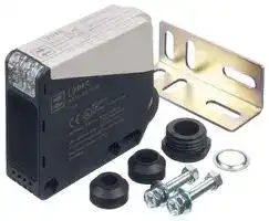


SA1U-D01MWT
Photoelectric Sensor, SA1U Series, 1 m, Diffuse, NPN / PNP, 10 V to 30 V, Time Delay
- Manufacturer: IDEC
- Product type:
- Sensing Range Max:1m; Sensing Method:Diffuse Reflective; Sensor Output:NPN / PNP; Product Range:SA1U Series; Connection Method:Screw Terminals; Supply Voltage DC Min:10V; Supply
- SVHC: No SVHC (15-Jan-2019)
- Product Range: SA1U Series
- Sensing Method: Diffuse Reflective
- Connection Method: Screw Terminals
- Sensing Range Max: 1m
- Sensor Output Type: NPN / PNP
- Supply Voltage Max: 30V
- Supply Voltage Min: 10V
- Sensing Distance Max: 1m
- Supply Voltage DC Max: 30V
- Supply Voltage DC Min: 10V
| Delivery and price | |
|---|---|
| Units per pack | 50 |
| Price | 59.04 € |
| Current stock | 10+ |
| Lead time | 30 days |
## **SA1U Heavy-duty Photoelectric Sensor Features**

**==> picture [177 x 67] intentionally omitted <==**

**----- Start of picture text -----**<br>
————=<—" ‘ : a =ae - iS<br>_~<br>=e4: — £4<br>we = i<br>Now with<br> DC models!<br>**----- End of picture text -----**<br>


## **Part Numbers**

**Sensing Method Detectable Object Sensing Range Power  Voltage Control Output Included Accessories Time Delay Functions Part Numbers**

##

## **Universal Voltage**

**Sensing Method Through-beam Diffuse Background Suppression**

**www.idec.com    800-262-IDEC**

## **Dimensions (mm)**

## **DC Power Type**

## **SA1U**

**Sensing Method Through-Beam Polarized Retro-reflective Diffuse Background Suppression**

**==> picture [560 x 637] intentionally omitted <==**

**----- Start of picture text -----**<br>
25<br>22<br>Part Number SA1U-T50MW SA1U-PO7MW SA1U-DO01MW SA1U-BO2MW Polarized-reflective, —<br>Diffuse-reflective: receiver<br>Power SA1U-T50MWT SA1U-PO7MWT SA1U-DOIMWT — | SA1U-BO02IMWT Through-beam: projector/receiver eal<br> Voltage | B . 12 to 24V DC (10 to 30V DC) ripple rate 10% p-p maximum eeIN J)<br>Current Draw Projecto:Receiver: ats25mA max 30mA maximum INI||I|<br>= Diffuse-reflective: projector<br>+ | Type | NPN, PNP open collector (dual output) ae |<br>S £ Applied VoltageLoad Current || NPN: 100 mA maximum,30V DC maximum PNP: 100mA maximum Background supression: projectorPolarized-reflective: projector it<br>©oO | Voltage Drop NPN: 2.4V maximum, PNP: 2.4V maximum oei=<br>Response Time 1 ms maximum | JA<br>1 90<br>Insulation Resistance Between live and dead parts: 20MO minimum (500V DC megger) 85<br>Dielectric Strength Between live and dead parts: 1000V AC, 1 minute (| .<br>Un. eR Projector:Receiver ‘10 105 g , "0g I =—}<br>General Specifications<br>] o><br>Sensing Method Through-beam Polarized Retro-reflective Diffuse Background Suppression<br>LT 40<br>50<br>. . . 0.2 to 7m (when using . 0.2 to 2m (200 x 200 mm 7 55<br>Sensing Distance 50m maximum ; (200 x 200mm white .<br>supplied reflector IAC-R5) white matte paper)<br>matte paper)<br>Preset . — 0.4 to 2m (200 x 200 mm SA1U with Mounting Bracket<br>Distance white matte paper]<br>Polarized-reflective,<br>Diffuse-reflective: receiver<br>Detectable Object Opaque Opaque/Mirror surface Opaque/Transparent Opaque He<br>Hysteresis — — 20% of sensing 15% of sensing distance Through-beam: projector/receiver<br>y distance max. max. t I<br>Operation Mode Light ON or Dark ON (mode selector) Diffuse-reflective: projector =<br>Polarized-reflective: projector<br>[Projector]Power Background supression: projector A<br>LED: Pace B<br>Control Output [ Receiver]GreenOperation OperationP LED:- Yellow Operation LED: Yellow naa 2)<br>:<br>LED: Stable LED: Green<br>Light Stable Yellow LED: Green iSr— - —@))<br> Emitting Element Infrared LED (870nm) Red LED (660 nm) Infrared LED (870 nm) _——ee<br>Sensitivity Adjustment 1-turn control knob 8-turn control knob ty +t € =>-<br>VibrationImmunityExtraneous ResistanceLigh Sunlight:Damage limits:10,000 10lux to maximum, 55Hz, amplitudeIncandescent 1.5mm,lamp: 30 minutes5,000 luxin each maximum axis va—__}|<br>Shock Resistance Damage limits: 500 m/s?(50G), 3 shocks each in 6 axes 3 consecutive times 0.5 [<br>Operating Temperature -25 to +60°C (no freezing), storage temperature: -40 to +70°C Fe,<br>Operating Humidity 35 to 85% RH (no condensation), storage humidity: 35 to 85% RH 6 f}—ae l/<br>Connection Method Terminal block with M3 spring-up terminals<br>Applicable Cable Outside diameter 98 to 210 mm (core 0.3 to 0.75mm 2 )<br>Mounting Bracket<br>Cable Extension Extendable up to 100m with a cabtyre cable of 0.3mm? minimum 70<br>Housing Material PBT (indicator cover: PC) pt<br>Lens Material PC/PET PMMA PC/PET if fe |<br>Degree of Protection IP67 (IEC/EN60529) UY _<br>7.5 55<br>Time Delay Specifications 156 15<br>a<br>Sensing Method Through-beam Polarized Retro-reflective Diffuse Background Suppression<br>[Nae<br>Part Number SA1U-T50MT SA1U-PO7MT SA1U-DO1MT SA1U-B02MT ini ¢ — 4-4a<br>Time Range 0.1 to 5.0 sec (adjusted with a 1-turn control knob) ——<br>Time Delay Function One shot, ON delay, OFF delay, and normal (no time delay operation) modes == 2<br>R3<br>R3<br>10<br>40 10.5 10 5<br>30<br>67.5<br>5.5<br>49<br>28.5 29 34 39<br>1.2<br>52 27<br>76.5 76<br>14.5<br>14.5<br>27<br>6<br>27 11<br>14.5<br>**----- End of picture text -----**<br>


##

##

**www.idec.com    800-262-IDEC**

## **Models**

## **Without Time Delay**

**==> picture [187 x 69] intentionally omitted <==**

**----- Start of picture text -----**<br>
SA1U-T50M<br>SA1U-P07M<br>SA1U-D01M<br>Operation LED (yellow) (Note 2)<br>Sensitivity Control (Note 2)<br>Mode Selector (Light ON / Dark ON) 2<br>**----- End of picture text -----**<br>


Stable LED (green) (Note 1)

## SA1U-B02M

**==> picture [114 x 35] intentionally omitted <==**

**----- Start of picture text -----**<br>
Operation LED (yellow)<br>Sensing Range Control<br>Mode Selector (Light ON / Dark ON)<br>**----- End of picture text -----**<br>


## **With Time Delay**

SA1U-T50MT SA1U-P07MT SA1U-D01MT

**==> picture [122 x 123] intentionally omitted <==**

**----- Start of picture text -----**<br>
Operation LED (yellow) 2<br>Timer Control 2<br>Mode Selector 2 :<br>(Light ON / Dark ON, time delay mode)<br>Sensitivity Control 2<br>Stable LED (green) 1<br>**----- End of picture text -----**<br>


**==> picture [133 x 90] intentionally omitted <==**

**----- Start of picture text -----**<br>
SA1U-B02MT<br>Operation LED (yellow)<br>Timer Control<br>mn |@ne e|<br>**----- End of picture text -----**<br>


SA1U-B02MT Operation LED (yellow) Timer Control

Mode Selector (Light ON / Dark ON, time delay mode) Sensing Range Control

## **Output Circuit / Connection Diagram**

## **Universal Voltage Type                                 DC Voltage Type**

**==> picture [258 x 167] intentionally omitted <==**

**----- Start of picture text -----**<br>
All models except though-beam projector All models except though-beam projector Terminal No.<br>Terminal No.<br>Universal  1 Power supply 1 +V<br>voltage power supplycircuit 2 or 12 to 240V DC24 to 240V AC (50/60Hz) PNP 3 Load<br>5 Main circuit OUT +–12 to 24V<br>NCNO COM 4 Relay contactoutput (SPDT) NPNOUT 4 Load<br>3 2<br>0V<br>Internal Circuit External Connection<br>Though-beam projector Though-beam projector<br>Terminal No.<br>1 Power supply 1<br>2 24 to 240V AC (50/60Hz)or 12 to 240V DC Main circuit +–12 to 24V D<br>2<br>Internal Circuit External Connection<br>Main circuit<br>Main circuit<br>Universal voltage power supply circuit<br>**----- End of picture text -----**<br>


## **Terminal Arrangement**

**==> picture [112 x 134] intentionally omitted <==**

**----- Start of picture text -----**<br>
OOO 3 4 5<br>LUNES Ales<br>ip See)<br>1 2<br>one)<br>Operation Chart Incident<br>Interruption<br>Control  ON<br>Output OFF<br>Operation ON<br>LED OFF<br>Control  ON<br>Output OFF<br>Operation ON<br>L LED OFF<br>Light ON<br>Dark ON<br>**----- End of picture text -----**<br>


## **Output Circuit / Connection Diagram**

## **Terminal Arrangement**

## **Operation Chart**

**==> picture [261 x 226] intentionally omitted <==**

**----- Start of picture text -----**<br>
Mode<br>Operation Mode Selector Incident<br>Position Interruption<br>OFF delay 0 OFFON T T 7<br>Normal 1  ON<br>| | ef OFF<br>One shot 2 ON<br>OFF T T T<br>ON delay 3 OFFON T T<br>OFF delay 4 OFFON T T<br>Normal 5  ON<br>OFF<br>One shot 6 ON<br>OFF T T T<br>ON delay 7 OFFON ja T T<br>[zee=>S<br>8<br>Normal OFFON sed Ee<br>9<br>PE 7<br>Light ON<br>Dark ON<br>Light ON<br>**----- End of picture text -----**<br>


**www.idec.com    800-262-IDEC**

## **Characteristics (Typical) Through-beam  SA1U-T50M**

**==> picture [527 x 608] intentionally omitted <==**

**----- Start of picture text -----**<br>
40<br>(transparency 100  1% ND filter is used) (transparency 2000  2.8% ND filter is used) 30 ROE<br>SSS 1500 a 20 i<br>FS 1000 eee ee 10 itt | | | | ft | tt<br>10 ncaa 500 a Y 0 NS<br>0 X -10<br>AataSS SC CC tL| -500 eer te -20 SS S S θ ryE<br>OperationLevel 1 0 FEEEEEEEESe 10 20 30 40 50 60 70 80  EEE 90 100 110 120 130 140 150 -1000-1500-2000 Poe r -30-40 0 10 20 30 40 50 60 X70 80 90 100<br>Sensing Distance (m) 0 10 20 30 40 50 60 70 80 90 100 Sensing Distance X (m)<br>Sensing Distance X (mm)<br>Polarized Retro-reflective  SA1U-P07M<br>Excess Gain Lateral Displacement Angle<br>100 140120 IAC-R8 60<br>= SSS SS SS 100 a IAC-R5 40 [~— | IAC-RS2<br>——————— 80 a IAC-R6 i IAC-R8<br>60 IAC-R7 20 —_<br>40<br>10 eee] 200 IAC-RS1 IAC-RS2 0 IAC-RS1 IAC-R7 1 IAC-R5 7<br>—_\d IAC-R7 — ee _— IAC-RS2 a — ——ee IAC-R6 — IAC-R8 ——SS]> IAC-R5 —a -20-40-60 AOehi A NeA [Tt] NA 5 Y -20 INe eS | eV be [|eSr IAC-R6 d θ<br>OperationLevel 1 IAC-RS1 -100-80 X -40 X<br>0 l | 1 2 3 Sensing Distance (m)4 NETAN 5 6 7 TE 8 TI 9 10 -120-140 a -600 oo 2 4 6 a 8 10<br>0 1 2 3 4 5 6 7 8 9 10 Sensing Distance X (m)<br>Sensing Distance X (mm)<br>Diffuse  SA1U-D01M<br>Excess Gain Lateral Displacement Object Size vs. Sensing Distance<br>100 35 2200<br>= 25 Pt ttt tt yt yt 2000 [] | [ Lee ee<br>BSRESSSSSSSS 15 FOOT) 1800 eee eco<br>5<br>10 1600<br>pt} tt | | | | | | -5 HESS SSSs 44544 PTA | A an<br>A——— -15 a toot es ee eeATNX 1400 Object:    A mm X<br>Y 1200 white mat paper<br>-25 Object:<br>OperationLevel 1 0 PP 200  TT 400 600  Py 800 1000 1200 1400 Pe 1600 1800 eT 2000 2200 = X 200 x 200 mmWhite mat paper aeI 10000 yor7t 20  | 40 60 80 100 120 oe 140 160 | | 180 | 200<br>Sensing Distance (mm) -35 0 200 400 600 800 1000 1200 1400 1600 1800 2000 2200 Side Length A (mm)<br>Sensing Distance X (mm)<br>Background Suppression  SA1U-B02M<br>Lateral Displacement (preset 1m) Lateral Displacement (preset 2m) Light Beam Diameter<br>160<br>6040 a a ee Blackpaper ee 806040 a ee Blackpaper Fe Whitepaper 140120 aaA<br>20 White 20 100<br>0 paper 0 80<br>-20 -20 60<br>-40<br>-40 far 2 = e 40 ee<br>Y -60 Y<br>-60-80 0 X 200Object: 200 × 200 mm mat paperUse white mat paper for sensing distance setting400 a 600 ee 800 1000 -100-800 a 200X a 400 i 600 800 Py hk 1000 1200Object: 200 × 200 mm mat paper  settingUse white mat paper for sensing distance >t 1400 T 1600 1800 T 2000 2200 200 0 rea 500 ee 1000 eeee 1500 eeee 2000 ee 2500<br>Sensing Distance X (mm) Sensing Distance X (mm) Sensing Distance (mm)<br>Sensing Distance vs. Hysteresis Control Knob vs. Sensing Distance Colored Matte Paper and Other Materials<br>30<br>2520 PTPLTTy yt eT Black paper 5000450040003500 a pr ee ee WhitePaper r GrayPaper | 1000800600400 2 2<br>3000<br>15 200<br>PT tT tT T TTTyD Gray paper 2500 S Ft e ty Black 0 tVesHR2 ee |<br>10 (||| Lert 2000 a Paper a Comparison of sensing distance when set to detect white mat paper ( : 200) at 1m<br>1500 20001800<br>5 White paper 1000 16001400<br>0 | 0 200 | 400 setaeee 600 800 1000 1200 1400 1600 1800 2000 2200 ert | 5000 0 el S 1 2 3 4 a 5 6 7 8 12001000800600 |paoe ESF Se Ue ee<br>Sensing Distance (mm) Control Knob (turns) 4002000 1 Comparison of sensing distance when set to detect white mat paper (  IAA 200) at 2m<br>Excess Gain<br>Lateral Displacement Y (mm) Receiver Angle θ (º)<br>Excess Gain<br>Reflector Angle θ (º)<br>Lateral Displacement Y (mm)<br>Excess Gain<br>Lateral Displacement Y (mm) Sensing Distance X (mm)<br>Lateral Displacement Y (mm) Lateral Displacement Y (mm) Light Beam Diameter (mm)<br>Sensing Distance (mm) White Red Green Blue Gray Black Cardboard Aluminum Stainless Steel Brass Veneer<br>Hysteresis (%) Sensing Distance (mm)<br>Sensing Distance (mm) White Red Green Blue Gray Black Cardboard Aluminum Stainless Steel Brass Veneer<br>**----- End of picture text -----**<br>


IDEC Corporation  1175 Elko Drive  Sunnyvale, CA 94089  800-262-IDEC (4332)  Fax: 408-745-5258  www.idec.com/usa e e e e e ©2008 IDEC Corporation. All Rights Reserved.  12/08
Updated at April 23, 2026
Founded in 1945, IDEC is a globally recognized leader in industrial automation, machine safety, and control products. Renowned for pioneering innovations in Human-Machine Interface (HMI) systems, the company is dedicated to creating a safe and efficient harmony between advanced workplace technology and human operators. At the core of IDEC’s extensive portfolio is a comprehensive selection of high-performance relays designed for demanding industrial environments. This includes a broad range of electromechanical power relays, solid-state relays, contactors, and critical safety relays, supported by a wide array of specialized relay accessories to ensure reliable and efficient switching. Beyond switching components, IDEC provides complete solutions for modern control panels and automated systems. Their robust engineering extends to advanced panel displays and instrumentation, precision light sensors, and dependable AC/DC power converters. With additional offerings in industrial switches, visual signaling units, and DIN rail terminal blocks, IDEC equips engineers with the high-quality components required to build secure, next-generation automation infrastructure.
About Novapart
Novapart is a B2B electronic component broker specialising in stock shortages and cost reduction. We source hard-to-find parts and identify compliant alternatives across a catalogue of 410,000+ components from 500+ manufacturers.
Learn more →Stock Shortage Specialist
When a component is unavailable, discontinued or has an unacceptable lead time, we tap into our network of vetted European and Asian distributors to source what you need — without compromising on quality or traceability.
Request a quote →Compliant Alternatives
We identify pin-to-pin, electrically equivalent substitutes that meet the same certifications (RoHS, AEC-Q100, REACH) as your original specification — validated against datasheets, not just part numbers. Often at a lower cost.
BOM Analysis service →