


SA1E-LTP3C
Photoelectric Sensor, Datasensor, SA1E Series, 30 m, Through-Beam, PNP, 10 V to 30 V
- Manufacturer: IDEC
- Product type:
- Sensing Range Max:30m; Sensing Method:Through Beam; Sensor Output:PNP; Product Range:SA1E Series; Connection Method:M8 Connector; Supply Voltage DC Min:10V; Supply Voltage DC Max:
- SVHC: No SVHC (15-Jan-2019)
- Product Range: SA1E Series
- Sensing Method: Through Beam
- Connection Method: M8 Connector
- Sensing Range Max: 30m
- Sensor Output Type: PNP
- Supply Voltage DC Max: 30V
- Supply Voltage DC Min: 10V
| Delivery and price | |
|---|---|
| Units per pack | 50 |
| Price | 122.53 € |
| Current stock | 10+ |
| Lead time | 30 days |
**Sensors**
**SA1E**
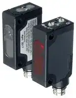
**SA1E Miniature Photoelectric Switches**
## **Key features:**
- Seven sensing methods: through-beam, polarized retroreflective, small beam reflective, diffuse, background suppression, convergent, and transparent.
- 2m cable type and M8 connector.
- NPN output, PNP output, light ON, dark ON can be selected.
- Coaxial polarized retro-reflective type (SA1E-X) available for sensing transparent objects.
- Background suppression (SA1E-B) type detects objects only, ignoring the background.
- Red LED available for easy alignment in long distance applications (SA1E-T, -P, -N, and -B)
- Convergent reflective type (SA1E-G) is ideal for detecting objects at a short distance with a background.
- Also available without sensitivity adjustment (SA1E-T, -P)
- Air blower mounting block for installing an air blower to clean the lens sur face. Ideal to maintain a clean lens surface and sensor performance.
- UL Listed and CE marked
- IP67
**==> picture [45 x 8] intentionally omitted <==**
**----- Start of picture text -----**<br>
C R US<br>**----- End of picture text -----**<br>
## **Part Numbers**
## **Photoelectric Switches**
|Sensing Method|Sensing Method|Sensing Method|Sensing Method|Sensing Range|Connection|Cable<br>Length|Operation<br>Mode|Part No.|Part No.|
|---|---|---|---|---|---|---|---|---|---|
|||||||||NPN Output|PNP Output|
|Through-beam|Infrared LED|w/Sensitivity<br>Adjustment|OU|10m<br>Cable<br>2m<br>Light ON<br>SA1E-TN1-2M<br>SA1E-TP1-2M<br>Dark ON<br>SA1E-TN2-2M<br>SA1E-TP2-2M<br>Connector<br>–<br>Light ON<br>SA1E-TN1C<br>SA1E-TP1C<br>Dark ON<br>SA1E-TN2C<br>SA1E-TP2C||||||
|||w/o Sensistivity<br>Adjustment||15m<br>Cable<br>2m<br>Light ON<br>SA1E-TN1-NA-2M<br>SA1E-TP1-NA-2M<br>Dark ON<br>SA1E-TN2-NA-2M<br>SA1E-TP2-NA-2M<br>Connector<br>–<br>Light ON<br>SA1E-TN1C-NA<br>SA1E-TP1C-NA<br>Dark ON<br>SA1E-TN2C-NA<br>SA1E-TP2C-NA||||||
||Red LED|w/Sensitivity<br>Adjustment||10m<br>Cable<br>2m<br>Light ON<br>SA1E-TAN1-2M<br>SA1E-TAP1-2M<br>Dark ON<br>SA1E-TAN2-2M<br>SA1E-TAP2-2M<br>Connector<br>–<br>Light ON<br>SA1E-TAN1C<br>SA1E-TAP1C<br>Dark ON<br>SA1E-TAN2C<br>SA1E-TAP2C||||||
||Class 1 Laser|w/Sensitivity<br>Adjustment||30m<br>Cable<br>2m<br>Light ON/<br>Dark ON<br>SA1E-LTN3-2M<br>SA1E-LTP3-2M<br>Connector<br>–<br>Light ON/<br>Dark ON<br>SA1E-LTN3C<br>SA1E-LTP3C||||||
## MipEc
1705151126
**www.IDEC.com**
210
**Sensors**
**SA1E**
## **Photoelectric Switches**
|Sensing Method|Sensing Method|Sensing Method|Sensing Method|Sensing Range|Connection|Cable<br>Length|Operation<br>Mode|Part No.|Part No.|
|---|---|---|---|---|---|---|---|---|---|
|||||||||NPN Output|PNP Output|
|Polarlized Retroflective|Red LED|w/Sensitivity Adjustment|(Note)<br>Note: Maintain at least the distance<br>shown in the ( ) between the SA1E<br>photoelectric switch and reflector.<br>Reflectors are not sup plied and<br>must be ordered separately.<br>See the characteristics on<br>page 219.<br>~~=~~|2.5m (100 mm)<br>When using IAC-R5/R8<br>1.5m (100 mm)<br>When using IAC-R6<br>1.3m (150 mm)<br>When using IAC-RS2<br>1.0m (150 mm)<br>When using IAC-RS1<br>0.8m (100 mm)<br>When using IAC-R5/R8<br>Cable<br>2m<br>Light ON<br>SA1E-PN1-2M<br>SA1E-PP1-2M<br>Dark ON<br>SA1E-PN2-2M<br>SA1E-PP2-2M<br>Connector<br>–<br>Light ON<br>SA1E-PN1C<br>SA1E-PP1C<br>Dark ON<br>SA1E-PN2C<br>SA1E-PP2C<br>~~|~~<br>[| |<br>[|<br>~~=~~||||||
|||w/o Sensitivity Adjustment||3.0m (100 mm)<br>When using IAC-R5/R8<br>2.0m (100 mm)<br>When using IAC-R6<br>1.4m (150 mm)<br>When using IAC-RS2<br>1.1m (150 mm)<br>When using IAC-RS1<br>1.0m (100 mm)<br>When using IAC-R7<br>Cable<br>2m<br>Light ON<br>SA1E-PN1-NA-2M<br>SA1E-PP1-NA-2M<br>Dark ON<br>SA1E-PN2-NA-2M<br>SA1E-PP2-NA-2M<br>Connector<br>–<br>Light ON<br>SA1E-PN1C-NA<br>SA1E-PP1C-NA<br>Dark ON<br>SA1E-PN2C-NA<br>SA1E-PP2C-NA<br>~~=~~<br>~~|~~<br>|<br>|<br>|<br>_<br>[|||||||
||Class 1 Laser|w/Sensistivity<br>Adjustment||10m<br>Cable<br>2m<br>Light ON/<br>Dark ON<br>SA1E-LPN3-2M<br>SA1E-LPP3-2M<br>Connector<br>–<br>Light ON/<br>Dark ON<br>SA1E-LPN3C<br>SA1E-LPP3C||||||
|Diffuse-reflective|Infrared LED|w/Sensitivity Adjustment|~~|~~|700 mm<br>Cable<br>2m<br>Light ON<br>SA1E-DN1-2M<br>SA1E-DP1-2M<br>Dark ON<br>SA1E-DN2-2M<br>SA1E-DP2-2M<br>Connector<br>–<br>Light ON<br>SA1E-DN1C<br>SA1E-DP1C<br>Dark ON<br>SA1E-DN2C<br>SA1E-DP2C<br> =z||||||
|Small-beam Reflective|Red LED|w/Sensitivity Adjustment|[J=1|50 to 150 mm<br>Cable<br>2m<br>Light ON<br>SA1E-NN1-2M<br>SA1E-NP1-2M<br>Dark ON<br>SA1E-NN2-2M<br>SA1E-NP2-2M<br>Connector<br>–<br>Light ON<br>SA1E-NN1C<br>SA1E-NP1C<br>Dark ON<br>SA1E-NN2C<br>SA1E-NP2C<br>0||||||
|Background Suppression|Red LED|w/Sensing Range<br>Adjustment||20 to 200 mm<br>Adjustable Sensing Range<br>20 to 200 mm<br>Cable<br>2m<br>Light ON<br>SA1E-BN1-2M<br>SA1E-BP1-2M<br>Dark ON<br>SA1E-BN2-2M<br>SA1E-BP2-2M<br>Connector<br>–<br>Light ON<br>SA1E-BN1C<br>SA1E-BP1C<br>Dark ON<br>SA1E-BN2C<br>SA1E-BP2C||||||
||Class 1 Laser|w/Sensitivity<br>Adjustment||20 to 300 mm<br>Adjustable Sensing Range<br>20 to 300 mm<br>Cable<br>2m<br>Light ON/<br>Dark ON<br>SA1E-LBN3-2M<br>SA1E-LBP3-2M<br>Connector<br>–<br>Light ON/<br>Dark ON<br>SA1E-LBN3C<br>SA1E-LBP3C<br>~~To~~||||||
1705151126
**800-262-IDEC** (4332) • USA & Canada
211
**Sensors**
**SA1E**
## **Photoelectric Switches**
|Sensing Method<br>Convergent Reflective<br>Infrared LED<br>w/Sensitivity Adjustment<br>Lv|Sensing Method<br>Convergent Reflective<br>Infrared LED<br>w/Sensitivity Adjustment<br>Lv|Sensing Method<br>Convergent Reflective<br>Infrared LED<br>w/Sensitivity Adjustment<br>Lv|||Sensing Range<br>5 to 35 mm<br>0|Sensing Range<br>5 to 35 mm<br>0|Connection<br>Cable<br>Connector|Cable<br>Length<br>2m<br>–|Operation<br>Mode<br>Light ON<br>Dark ON<br>Light ON<br>Dark ON|Part No.<br>NPN Output<br>PNP Output<br>SA1E-GN1-2M<br>SA1E-GP1-2M<br>SA1E-GN2-2M<br>SA1E-GP2-2M<br>SA1E-GN1C<br>SA1E-GP1C<br>SA1E-GN2C<br>SA1E-GP2C|
|---|---|---|---|---|---|---|---|---|---|---|
|Coaxial Polarized Retro-reflective<br>Red LED|w/Sensitivity Adjustment|Note: Reflector is not<br>supplied and<br>must be ordered<br>separately.<br>See characteris-<br>tics diagrams on<br>page 219.<br>~~=|~~oo|||oo|2.0m<br>(when using IAC-R9)<br>1.0m [100 mm]<br>(when using IAC-R10)<br>1.0m [100 mm]<br>(when using IAC-R11)<br>oo<br>||<br>=|Cable<br>Connector|2m<br>–|Light ON<br>Dark ON<br>Light ON<br>Dark ON|SA1E-XN1-2M<br>SA1E-XP1-2M<br>SA1E-XN2-2M<br>SA1E-XP2-2M<br>SA1E-XN1C<br>SA1E-XP1C<br>SA1E-XN2C<br>SA1E-XP2C|
## **For more information, visit www.IDEC.com/sensors**
## MipEc
1705151126
**www.IDEC.com**
212
**Sensors**
**SA1E**
## **Specifications**
|Sensing Method|Through-beam|Polarized<br>Retroreflective|Diffuse-reflective|Small-beam<br>Reflective|Background<br>Suppression (BGS)|Convergent<br>Reflective|Transparent|
|---|---|---|---|---|---|---|---|
|Part No.|SA1E-T|SA1E-P|SA1E-D|SA1E-N|SA1E-B|SA1E-G|SA1E-X|
|Power Voltage<br>Current Draw<br>Sensing Range<br>Adjustable Sensing<br>Range<br>Detectable Object<br>Hysteresis<br>Response Time<br>Sensitivity Adjustment<br>Sensing Range<br>Adjustment<br>Light Source Element<br>Operation Mode<br>Control Output<br>LED Indicators<br>Interference Prevention<br>Degree of Protection<br>Extraneous Light<br>Immunity<br>Operating Temperature<br>Operating Humidity<br>Storage Temperature<br>Insulation Resistance|12 to 24V DC (Operating range: 10 to 30V DC)<br>Equipped with reverse-polarity protection<br>Projector:<br>15 mA<br>Receiver:<br>20 mA<br>Laser<br>Receiver:<br>30 mA<br>30 mA<br>with laser: 35 mA<br>20 mA maximum<br>With sensitivity<br>adjustment: 10m<br>Laser models: 30m<br>With sensitivity<br>adjustment:<br>2.5m (IAC-R5/R8)<br>1.5m (IAC-R6)<br>1.3m (IAC-RS2)<br>1.0m (IAC-RS1)<br>0.8m (IAC-R7)1<br>Laser models<br>0.3-10m<br>700 mm<br>(using 200 × 200<br>mm white mat<br>paper)<br>50 to 150 mm<br>(using 100 × 100<br>mm white mat<br>paper)<br>20 mm to preset<br>(using 200 × 200<br>mm white mat<br>paper)<br>with laser: 20 -<br>300mm<br>5 to 35 mm<br>(using 100 × 100<br>mm white mat<br>paper)<br>2m<br>(when using<br>IAC-R9)<br>Without sensitivity<br>adjustment: 15m<br>Without sensitivity<br>adjustment:<br>3.0m (IAC-R5/R8)<br>2.0m (IAC-R6)<br>1.4m (IAC-RS2)<br>1.1m (IAC-RS1)<br>1.0m (IAC-R7)1<br>—<br>40 to 200 mm<br>with laser: 40-300mm —<br>—<br>Opaque<br>Opaque/Transparent<br>Opaque<br>Opaque/<br>Transparent<br>Opaque, transpar-<br>ent and mirror-like<br>objects<br>—<br>20% maximum<br>10% maximum<br>20% maximum<br>—<br>1 ms maximum<br>with laser: 250us<br>500 μs maximum<br>Adjustable using a potentiometer (approx. 260°)<br>Through-beam type and polarized retroreflective type are also available without<br>sensitivity adjustment.<br>Laser models: 2 turn adjustment<br>—<br>Adjustable using<br>a potentiometer<br>(approx. 260°)<br>Adjustable using<br>a potentiometer<br>(approx. 240°)<br>—<br>6-turn control knob<br>—<br>—<br>Infrared LED<br>Red LED<br>Red laser diode<br>Red LED<br>Red laser diode<br>Infrared LED<br>Red LED<br>Red LED<br>Red laser diode<br>Infrared LED<br>Red LED<br>Light ON/Dark ON<br>NPN open collector or PNP open collector<br>30V DC, 100 mA maximum<br>Voltage drop: 1.2V maximum (BGS type: 2V maximum)<br>Short-circuit protection<br>Operation LED:<br>Yellow<br>Stable LED: Green<br>Power LED: Green (Through-beam type projector)<br>Operation LED:<br>Yellow<br>Stable LED: None<br>Operation LED:<br>Yellow<br>Stable LED: Green<br>Operation LED:<br>Yellow<br>Stable LED: None<br>—<br>Two units can be mounted in close proximity.<br>IP67 (IEC 60529)<br>Sunlight: 10,000 lux maximum, Incandescent lamp: 5,000 lux maximum (at receiver)<br>–25 to +55°C (no freezing)<br>35 to 85% RH (no condensation)<br>–40 to +70°C (no freezing)<br>Between live part and mounting bracket: 20 MΩ maximum (500V DC megger)|||||||
1705151126
**800-262-IDEC** (4332) • USA & Canada
213
**Sensors**
**SA1E**
## **Specifications, con’t**
|Sensing Method|Through-beam|Polarized<br>Retroreflective|Diffuse-reflective|Small-beam<br>Reflective|Background<br>Suppression (BGS)|Convergent<br>Reflective|Transparent|
|---|---|---|---|---|---|---|---|
|Part No.|SA1E-T|SA1E-P|SA1E-D|SA1E-N|SA1E-B|SA1E-G|SA1E-X|
|Dielectric Strength<br>Vibration Resistance<br>Shock Resistance<br>Material<br>Attachments<br>Weight<br>(approx.)<br>Cable<br>Model<br>Connector<br>Model<br>Connection<br>Method<br>Cable<br>Model<br>Connector<br>Model|Between live part and mounting bracket: 1000V AC, 50/60 Hz, 1 minute<br>Damage limits: 10 to 55 Hz, Amplitude 0.75 mm, 20 cycles in each of 3 axes<br>Damage limits: 500 m/s2, 10 shocks in each of 3 axes<br>Housing: PC/PBT, Lens: PC (Polarized retroreflective / coaxial polarized retro-reflective: PMMA), Indicator cover: PC<br>Instruction sheet<br>Projector:<br>30g<br>Laser Projector: 35g<br>Receiver:<br>30g2<br>Laser Receiver: 35g<br>30g2<br>with laser: 35g<br>35g3<br>30g2<br>35g3<br>Projector:<br>10g<br>Laser Projector: 20g<br>Receiver:<br>10g<br>Laser Receiver: 20g<br>10g<br>with Laser 20g<br>20g<br>10g<br>20g<br>ø3.5 mm, 3-core, 0.2 mm2, 1-m vinyl cabtyre cable (2-core for the projector of through-beam type)<br>M8 connector (4-pin)|||||||
1. Maintain at least the distance shown below between the SA1E photoelectric switch and reflector.
- IAC-R5/R6/R7 /R8: 100 mm
- IAC-RS1/RS2: 150 mm The detection distance cannot be guaranteed if the reflector is deformed or the tape type reflector is applied on uneven surface.
2. Cable length: 1m (50g when the cable length is 2m, 55g for laser models. 110g when the cable length is 5m, 120g for laser models.)
3. Cable length: 1m (55g when the cable length is 2m. 120g when the cable length is 5m.)
4. For laser models insert L in place of .
## **Slit and Sensing Range**
A slit, which changes the beam size of through-beam sensors, can easily be attached to the sensing side of the through-beam projector and receiver. Three different slit widths are available.
|Slit|Slit|w/Sensitivity Adjustment|w/Sensitivity Adjustment|w/Sensitivity Adjustment|w/Sensitivity Adjustment|w/o Sensitivity Adjustment|w/o Sensitivity Adjustment|w/o Sensitivity Adjustment|w/o Sensitivity Adjustment|
|---|---|---|---|---|---|---|---|---|---|
|||Sensing Range (m)||Minimum Detectable<br>Object Width (mm)||Sensing Range (m)||Minimum Detectable<br>Object Width (mm)||
|Part No.|Slit Width: A|Used on<br>one side|Used on<br>both sides|Used on<br>one side|Used on<br>both sides|Used on<br>one side|Used on<br>both sides|Used on<br>one side|Used on<br>both sides|
|SA9Z-S06<br>SA9Z-S07<br>SA9Z-S08<br>SA9Z-S09<br>SA9Z-S10<br>SA9Z-S11<br>SA9Z-S12<br>SA9Z-S13<br>SA9Z-S14|0.5 mm<br>1.0 mm<br>2.0 mm<br>0.5 mm<br>1.0 mm<br>2.0 mm<br>0.5 mm<br>1.0 mm<br>2.0 mm|2.5<br>3.5<br>6.0<br>2.0<br>3.0<br>5.5<br>0.8<br>1.5<br>2.5|1.0<br>1.5<br>3.5<br>0.7<br>1.5<br>3.0<br>0.08<br>0.3<br>1.2|7.0<br>7.0<br>7.0<br>7.0<br>7.0<br>7.0<br>5.0<br>5.0<br>5.0|0.5<br>1.0<br>2.0<br>0.4<br>0.7<br>1.5<br>0.3<br>0.6<br>1.5|5.0<br>7.0<br>9.0<br>4.0<br>7.0<br>9.0<br>1.3<br>2.5<br>5.5|1.5<br>3.0<br>5.5<br>1.5<br>2.5<br>5.0<br>0.1<br>0.3<br>1.6|7.0<br>7.0<br>7.0<br>7.0<br>7.0<br>7.0<br>5.0<br>5.0<br>5.0|0.5<br>1.0<br>2.0<br>0.5<br>0.8<br>1.5<br>0.5<br>0.6<br>1.7|
Horizontal slits and round slits have an orientation. Make sure that the TOP marking comes on top of the sensor (LED side).
Used on one side: Slit is attached to the receiver only.
MipEc
1705151126
**www.IDEC.com**
214
**Sensors**
**SA1E**
## **Output Circuit & Wiring Diagram**
**==> picture [562 x 580] intentionally omitted <==**
**----- Start of picture text -----**<br>
NPN Output PNP Output Through-beam Type Projector<br>+V +V +V<br>1 1 1<br>Brown Brown Brown<br>12 to 24V DC<br>Black OUT<br>4 4 12 to 24V DC<br>OUT Black<br>12 to 24V DC<br>0V 0V 0V<br>3 3 3<br>Blue Blue Blue<br>(Connector Pin Assignment) (Connector Pin Assignment)<br> (0V) (0V)<br> (OUT) (NC)<br> (NC) (NC)<br> (+V) (+V)<br>E S ES<br>Dimensions (mm)<br>Vertical Slit 8.2 Horizontal Slit 8.2 Round Slit 8.2 6.1<br>SA9Z-S06 A 6.1 SA9Z-S09 6.5 6.1 SA9Z-S12<br>SA9Z-S07 SA9Z-S10 SA9Z-S13<br>SA9Z-S08 SA9Z-S11 SA9Z-S14<br>Material: Stainless Steel<br>Cable Model<br>Through-beam<br>13.4 Operation LED (yellow) [1]<br>9.0<br> •Through-beam •Polarized retrorefl ective<br> •Diffuse-refl ective<br> •Small-beam refl ective<br> •Convergent Refl ective<br>Stable LED (green) [2] Sensitivity Control [2 4]<br>10.8 10.8 19.5<br>6.5 6.5 3.4<br>(Note 3)<br>oO.<br>Polarized retroreflective Projector<br>Diffuse-reflectiveSmall-beam reflective Receiveror Receiver<br>Convergent reflective<br>Projector<br>2-M3<br>g eo<br>1. Power ON LED (green) for through-beam projector<br>2. No sensitivity control and stable LED are attached on the through-beam projector.<br>3. 5.2 mm for polarized retroreflective type<br>øA<br>ø3.5 5<br>OI Touchscreens<br>Load<br>Main Circuit Main Circuit Main Circuit<br>Load<br>PLCs<br>4.4<br>A<br>32.1 18 32.1 4.4 32.1 0.3 Automation Software<br>0.3<br>0.3<br>Power Supplies<br>2.9<br>10.8<br>1.2<br>Sensors<br>17.4 17.4 8.8 31.5 25.4<br>17.1<br>12.7<br>4.0<br>7.1<br>Communication<br>**----- End of picture text -----**<br>
**==> picture [202 x 8] intentionally omitted <==**
**----- Start of picture text -----**<br>
4. No sensitivity control is installed on the type without sensitivity adjustment.<br>**----- End of picture text -----**<br>
1705151126
**800-262-IDEC** (4332) • USA & Canada
215
**Sensors**
**SA1E**
**==> picture [529 x 660] intentionally omitted <==**
**----- Start of picture text -----**<br>
Cable Model<br>Background Suppression (BGS)<br>11.0<br>7.5 Operation LED<br>(Yellow)<br>Note 1 Sensing RangeControl (6 turns)<br>10.8<br>19.5<br>6.4<br>3 i 3.4 |i<br>Receiver<br>1. Stable LED is not provided on the background suppres-<br>sion type.<br>Projector<br>i<br>fi<br>cae<br>2-M3<br>Cable Model<br>Coaxial Polarized Retro-reflective<br>14.5<br>11.0<br>19.5 Sensitivity Control<br>3.4<br>Projector,<br>Receiver<br>1. Stable LED is not provided on the coaxial polarized (coaxial)<br>retro-reflective type.<br>4 {-<br>2-M3<br>Cable Model (Laser) fH 15.3 Operation LED (yellow) (Note 2)<br>Through-beamPolarized Retroreflective 8.211.8 Operation Mode Switch (Note 1)<br>Background Suppression<br>Operation LED (green) (Note 1)<br>Sensitivity Control (except BGS) (Note 1)<br>Sensing Range Control (BGS)<br>19.5<br>Projector<br>or Receiver<br>Receiver (Polarized Retroreflective)<br>5<br>1. Stable LED is not provided on the coaxial polarized<br>retro-reflective type.<br>(Note 3)<br>Projector<br>2-M3 3.4<br>T fig) 7.8 TX<br>ø5.2<br>ø3.5<br>ø3.5<br>ø3.5<br>2.9<br>OI Touchscreens<br>0.9<br>PLCs<br>19.4 31.5 25.4<br>6.7<br>Automation Software 2.9<br>10.8<br>0.9<br>Power Supplies<br>31.5 25.4<br>17.2<br>4.5<br>Sensors<br>3.2<br>10.8<br>1.2<br>Communication<br>19.8 8.0 31.5 25.4<br>17.1<br>7.2<br>Barriers<br>**----- End of picture text -----**<br>
MipEc
1705151126
**www.IDEC.com**
216
**Sensors**
**SA1E**
## **Connector Model**
**==> picture [450 x 217] intentionally omitted <==**
**----- Start of picture text -----**<br>
Through-beam<br> •Through-beam •Polarized retrorefl ective 9.013.4 Operation LED (yellow) [1]<br> •Diffuse-refl ective<br> •Small-beam refl ective<br> •Convergent Refl ective<br>Sensitivity Control [2 4]<br>Stable LED (green) [2]<br>10.8 10.8 19.5<br>6.5 6.5 3.4<br>WU (Note 3)<br>Projector<br>or<br>Receiver Receiver<br>Polarized retroreflective Projector<br>Diffuse-reflective<br>Small-beam reflective<br>Convergent reflective<br>2-M3<br>(Note 5)<br>M8 ×1<br>2.9<br>10.8<br>1.2<br>17.4 17.4 8.8 31.5 25.4<br>17.1<br>12.7<br>4.0<br>7.1<br>4.5<br>6.3<br>**----- End of picture text -----**<br>
1. Power ON LED (green) for through-beam projector
2. No sensitivity control and stable LED are attached on the through-beam projector.
3. 5.2 mm for polarized retroreflective type
4. No sensitivity control is installed on the type without sensitivity adjustment.
## **Connector Model**
**==> picture [380 x 390] intentionally omitted <==**
**----- Start of picture text -----**<br>
11.0<br>7.5 Operation LED<br>(Yellow)<br>Sensing Range<br>(Note 1) Control (6 turns)<br>10.8 19.5<br>6.4 3.4<br>Receiver<br>f Projector<br>1. Stable LED is not provided on the background<br>suppression type.<br>2. The connector length is 18 mm when a right-angle connec-<br>tor cable. : | le<br>(Note 2) 2-M3 M8 x 1<br>14.5<br>11.0<br>19.5<br>3.4<br>Projector,<br>Receiver<br>(coaxial)<br>1. Stable LED is not provided on the coaxial polarized<br>retro-reflective type.<br>2-M3<br>M8<br>ø5.2<br>2.9<br>0.9<br>19.4 31.5 25.4<br>6.7<br>4.5<br>6.2<br>2.9<br>10.8<br>0.9<br>31.5 25.4<br>4.5 17.2<br>4.5<br>6.3*<br>**----- End of picture text -----**<br>
Background Suppression (BGS)
**==> picture [108 x 21] intentionally omitted <==**
**----- Start of picture text -----**<br>
Connector Model<br>Coaxial Polarized Retro-reflective<br>**----- End of picture text -----**<br>
1705151126
**800-262-IDEC** (4332) • USA & Canada
217
**Sensors**
**SA1E**
**==> picture [541 x 659] intentionally omitted <==**
**----- Start of picture text -----**<br>
Connector Model (Laser) 15.3 Operation LED (yellow) (Note 2)<br>Through-beam 11.8 Operation Mode Switch (Note 1)<br>8.2<br>Polarized Retroreflective 1]<br>Background Suppression<br>Operation LED (green) (Note 1)<br>Sensitivity Control (except BGS) (Note 1)<br>Sensing Range Control (BGS)<br>19.5<br>Projector<br>or Receiver<br>Receiver (Polarized Retroreflective)<br>A } a y IG<br>MB A |<br>1. Stable LED is not provided on the coaxial polarized<br>retro-reflective type.<br>L i<br>| | ToST Projector _—,.<br>4.5 2-M3<br>a Tg M8×1<br>a 7.8 3.4 i<br>1-1. Through-beam SA1E-T (Infrared LED w/sensitivity adjustment)<br>SA1E-TA (Red LED) w/sensitivity adjustment)<br>Excess Gain (Without slit) Lateral Displacement (Without slit) Angle (Without slit)<br>100 600 60<br>400 40<br>200 20<br>a Poe TEN Neeee eee<br>10 0 0<br>Y<br>-200 -20<br>θ<br>X<br>-400 -40<br>Operation Level 1 -600 -60 X<br>0 P| 5 10 EY 15 20 0 a 5 10 e 15 20 0 a a<br>Sensing Distance (m) Sensing Distance X (m) Sensing Distance X (m)<br>Excess Gain (With vertical slit) Excess Gain (With horizontal slit) Excess Gain (With round slit)<br>100 100 100<br>SSS SSS ===<br>1.0 mmslits onboth sides 0.5 mmslits onboth sides 1.0 mmslits onboth sides ø0.5mmslits onboth sides<br>10 ee 10 Eo 10<br>ø2.0mm<br>2.0 mm 2.0 mm slits on<br>slits on slits on ø1.0mm both sides<br>Operation 0.5 mmslits on both sides both sides slits onboth sides<br>Level 1 PASSES both sides SNP 1 ARS| NAP TSE 1 0 CAN| \ 0.5 1.0 1.5 PN 2.0 2.5 3.0<br>0 1 2 3 4 5 6 7 8 0 1 2 3 4 5 6 7<br>Sensing Distance (m) Sensing Distance X (m) Sensing Distance X (m)<br>Lateral Displacement (With 0.5-mm vertical slit) Lateral Displacement (With 1.0-mm vertical slit) Lateral Displacement (With 2.0-mm vertical slit)<br>200 250 400<br>150 200 300<br>100 One slit on 150 One slit onreceiver 200 One slit on<br>50 pew receiver 10050 100 receiver<br>0 — Slits onboth sides | 0 Eee Slits onboth sides 0 Eee Slits onboth sides N<br>-50 <= a -50 ==eee -100 aaeso<br>-100 mE -100 Ke| _| —~ || -200 ea p eT|_|<br>Y -150 Y Y<br>-150 -200 -300<br>-200 a X — _ -250 _ X => —— -400 | a X = ~<br>0 1 2 3 4 5 6 0 2 4 6 8 0 2 4 6 8 10 12<br>Sensing Distance (m) Sensing Distance X (m) Sensing Distance X (m)<br>3.2<br>10.8<br>OI Touchscreens<br>1.2<br>PLCs 19.8 8.0 31.5 25.4<br>17.1<br>7.2<br>6.3<br>Automation Software<br> (°)<br><br>Excess Gain<br>Reflector Angle<br>Lateral Displacement Y (mm)<br>Power Supplies<br>Excess Gain<br>Sensors Excess Gain Excess Gain<br>Communication Lateral Displacement Y (mm)<br>Lateral Displacement Y (mm) Lateral Displacement Y (mm)<br>Barriers<br>**----- End of picture text -----**<br>
MipEc
1705151126
**www.IDEC.com**
218
**Sensors**
**SA1E**
## **Characteristics (Typical)**
**==> picture [462 x 647] intentionally omitted <==**
**----- Start of picture text -----**<br>
Lateral Displacement (With 0.5-mm horizontal slit) Lateral Displacement (With 1.0-mm horizontal slit) Lateral Displacement (With 2.0-mm horizontal slit)<br>150 200 250<br>150 200 One slit on<br>100 Tr One slit on 100 oS One slit on 150 receiver<br>50 naa receiver Lee receiver 100 ZS<br>0 = Slits onboth sides Y 500 Lt Slits onboth sides ; Y 500 [Z=—_ Slits onboth sides | XN Y<br>-50 -50<br>-50 X X -100 X<br>— N -100 | IN | wm<br>-100 -150<br>= -150 i ee -200<br>-150 0 | | 1 | 2 [Pr 3 4 | 5 -200 0 a 1 2 3 4 5 6 7 -250 0 EF 2 4 6 8 10<br>Sensing Distance (m) Sensing Distance X (m) Sensing Distance X (m)<br>Lateral Displacement (With ø0.5-mm round slit) Lateral Displacement (With ø1.0-mm round slit) Lateral Displacement (With ø2.0-mm round slit)<br>50 80 150<br>4030 TTT TTT One slit on yyy 6040 Pty One slit on 100 One slit on<br>2010 Hea receiver 20 aN Pe receiver 50 ETN receiver<br>-100 Slits onboth sides Y -200 Slits onboth sides Y 0 Slits onboth sides Y<br>-20 X X -50 X<br>-40<br>-30-40 2aeEEE e 7 -60 | ee aeZ| -100 po=a,<br>-500 a 0.2 0.4 0.6 0.8 PEE 1.0 1.2 1.4 1.6 -800 PoP 0.5 1.0 EP 1.5 PT 2.0 2.5 3.0 3.5 -1500 OSE 1 2 3 | 4 5 6<br>Sensing Distance (m) Sensing Distance X (m) Sensing Distance X (m)<br>1-2. Through-beam SA1E-T -NA (Infrared LED w/o sensitivity adjustment)<br>Excess Gain (Without slit) Lateral Displacement (Without slit) Angle (Without slit)<br>100 1000 80<br>800 60<br>SSS SSS 600 a Fe a<br>40<br>400<br>ee ee 200 ee ee 20 A ee eee ee<br>10 | | | | 0 eo 0 ee<br>SS -200 —————EE -20 a ae<br>-400<br>Y -40 θ<br>es -600 [ [———L_ | --ty<br>Operation -800 X -60 X<br>Level 1 0 FoF 5 TTT 10 15 20 25 30 -1000 0 5 10 15 20 -80 0 PT 5 10 15 20<br>Sensing Distance (m) Sensing Distance X (m) Sensing Distance X (m)<br>Excess Gain (With vertical slit) Excess Gain (With horizontal slit) Excess Gain (With round slit)<br>100 SS 1.0 mmslits onboth sides 100 SSS SS 1.0 mmslits onboth sides = 100 SS ø0.5 mmslits onboth sides<br>10 10 10<br>2.0 mm ø2.0 mm<br>slits on 2.0 mm slits on<br>0.5 mmslits on both sides 0.5 mmslits on slits onboth sides ø1.0 mmslits on both sides<br>Operation both sides both sides both sides<br>Level 1 0 Cex 2 VN 4 6 ESN 8 10 12 | 1 0 PARZSS 2 -N 4 TN 6 8 10 12 1 0 ——— 0.5 “ 1.0 1.5 2.0 2.5 — 3.0<br>Sensing Distance (m) Sensing Distance X (m) Sensing Distance X (m)<br>Lateral Displacement (With 0.5-mm vertical slit) Lateral Displacement (With 1.0-mm vertical slit) Lateral Displacement (With 2.0-mm vertical slit)<br>250 300 500<br>200 One slit 400 Y<br>150 One sliton receiver 200 on receiver 300 X<br>100500 [eraan Slits onboth sides 1000 |Za Slit onboth sides 2001000 a Slit onboth sides ——e— One sliton receiver<br>-50 -100<br>-100 -100 Y -200<br>-150-200 Y w s -200 NS X | -300-400 SS<br>— X —— PSST Ee -500 pT SS<br>-250 0 a 2 4 6 8 10 -300 0 | 5 10 15 0 re 5 10 15 20<br>Sensing Distance (m) Sensing Distance X (m) Sensing Distance X (m)<br>Lateral Displacement Y (mm)<br>Lateral Displacement Y (mm) Lateral Displacement Y (mm)<br>Lateral Displacement Y (mm)<br>Lateral Displacement Y (mm) Lateral Displacement Y (mm)<br> (°)<br><br>Excess Gain<br>Reflector Angle<br>Lateral Displacement Y (mm)<br>Excess Gain<br>Excess Gain Excess Gain<br>Lateral Displacement Y (mm)<br>Lateral Displacement Y (mm) Lateral Displacement Y (mm)<br>**----- End of picture text -----**<br>
1705151126
**800-262-IDEC** (4332) • USA & Canada
219
**Sensors**
**SA1E**
## **Characteristics (Typical)**
**==> picture [479 x 559] intentionally omitted <==**
**----- Start of picture text -----**<br>
Lateral Displacement (With 0.5-mm horizontal slit) Lateral Displacement (With 1.0-mm horizontal slit) Lateral Displacement (With 2.0-mm horizontal slit)<br>200150 ER 400300 a 400300 EY<br>100 One slit 200 One slit 200 One slit<br>on receiver on receiver on receiver<br>50 100 100<br>0 Slits onboth sides 0 Slits onboth sides 0 Slits onboth sides<br>-50 — _ -100 ar fT -100 e f Y<br>-100 Y -200 -200 X<br>-150 X -300 Y -300<br>-200 0 POPSE 2 4 6 eeEa 8 10 -400 0 2 X2 “kT 4 6 8 10 -400 0 |SS| 5 NN 10 15 20<br>Sensing Distance (m) Sensing Distance X (m) Sensing Distance X (m)<br>Lateral Displacement (With ø0.5-mm round slit) Lateral Displacement (With ø1.0-mm round slit) Lateral Displacement (With ø2.0-mm round slit)<br>60 200 200<br>150 Y 150 Y<br>40<br>20 TR, One sliton receiver 7 100 etJ X ee)7H One slit 100 e X p e One sliton receiver e<br>50 on receiver 50<br>0 b Slits onboth sides ee 0 E Slits onboth sides ee 0 p Slits onboth sides ee<br>Y -50 -50<br>-20<br>-40-60 0 2aS 0.5 te} 1.0 1.5 4e X 2.0 e 2.5 3.0 -100-150-200 0 ASSSER,esa 1 2 3 4 5 6 -100-150-200 0 AREa 1 2 3 4 5 6<br>Sensing Distance (m) Sensing Distance X (m) Sensing Distance X (m)<br>2-1. Polarized Retroreflective SA1E-P (Red LED w/sensitivity adjustment)<br>Excess Gain Lateral Displacement Angle (when using IAC-R5/-R8)<br>100 8060 Y 60 IAC-RS1 θ<br>X IAC-R5/8 40<br>40<br>SS=S5 20 72 55) IAC-R6 20 Ae X IAC-R5/8<br>10 0 IAC-RS1 IAC-RS2 0 IAC-R7∗ IAC-RS2 IAC-R6<br>— SO COS S N<br>-20 IAC-R7∗<br>-20<br>IAC-R5/8 -40<br>IAC-R7∗ -40<br>Operation IAC-RS1 -60<br>Level 1 y ANN IAC-RS2 IAC-R6 -80 SL -60 L<br>0 1 NA 2 XN 3 4 5 0 ed 1 2 3 4 5 AA 0 1 2 3 4 5<br>Sensing Distance (m) Sensing Distance X (m) Sensing Distance X (m)<br>2-2. Polarized Retroreflective SA1E-P -NA (Red LED w/o sensitivity adjustment)<br>Excess Gain Lateral Displacement Angle (when using IAC-R5/-R8)<br>100 80 60<br>Y θ<br>60<br>===—— a X m 40<br>10 ———— 40 = I IAC-R7 = ∗ | IAC-R5/8 | 20 (y e X t<br>20 IAC-R7∗ IAC-RS2<br>IAC-R7∗ IAC-R6 IAC-R5/8 0 IAC-RS1 IAC-RS2 IAC-R6 0 IAC-RS1 IAC-R6 IAC-R5/8<br>1 IAC-RS1 IAC-RS2 -20 -20<br>0 1 2 3 4 5 -40<br>PA S S S T -40 a<br>Operation -60 ae 24ne pal<br>Level a -60 Le<br>-80 0 1 2 3 4 5 0 1 2 3 4 5<br>Sensing Distance (m) Sensing Distance X (m) Sensing Distance X (m)<br>OI Touchscreens<br>Lateral Displacement Y (mm)<br>Lateral Displacement Y (mm) Lateral Displacement Y (mm)<br>PLCs<br>Lateral Displacement Y (mm)<br>Lateral Displacement Y (mm) Lateral Displacement Y (mm)<br>Automation Software<br> (°)<br><br>Excess Gain<br>Power Supplies<br>Reflector Angle<br>Lateral Displacement Y (mm)<br>Sensors<br> (°)<br><br>Excess Gain<br>Reflector Angle<br>Lateral Displacement Y (mm)<br>Communication<br>**----- End of picture text -----**<br>
MipEc
1705151126
**www.IDEC.com**
220
**Sensors**
**SA1E**
## **Characteristics (Typical)**
**==> picture [209 x 11] intentionally omitted <==**
**----- Start of picture text -----**<br>
3. Diffuse-Reflective SA1E-D (Infrared LED w/sensitivity adjustment)<br>**----- End of picture text -----**<br>
**==> picture [454 x 529] intentionally omitted <==**
**----- Start of picture text -----**<br>
Excess Gain Lateral Displacement Object Size vs. Sensing Distance<br>100 100 1400<br>80<br>SS 60 pj ff tt | 1200 a<br>ne 40 4-44 1000 eT<br>20 800<br>10 0<br>eee -20 —— 600 4<br>A<br>Pp oN -40 a Y 400 San X s<br>Operation Level 1 Po 0 P| 200 400 | CUT 600 NTT 800 1000 1200 -100-60-800 200X Object: 200 × 200 mm400 600white mat paper800 1000 | 1200 2000 0 a 50 Object: 100 im white mat paperA mm150 200<br>Sensing Distance (mm) Sensing Distance X (mm) Sensing Distance X (mm)<br>4. Small-beam Reflective SA1E-N (Red LED w/sensitivity adjustment)<br>Excess Gain Lateral Displacement Object Size vs. Sensing Distance<br>100 15 300<br>=== 10 P| | ft 250 | | EL<br>es 5 Po | | 200 pf | | |<br>10 FF 0 Lr 150<br>A<br>Ff ~~| -5 |;ooSA I 100 P/|J faz| X || [|]<br>Operation Level 1 0 a=SY 50 100 150 200 250 -10-15 0 ee X 50 l Y Object: 100 white mat paper100 ×150 100 mm200 250 N 500 0 |-| 20 40Object: q white mat paper60A mm 80 100<br>Sensing Distance (mm) Sensing Distance X (mm) Sensing Distance X (mm)<br>5. Background Suppression SA1E-B (Red LED w/sensitivity adjustment)<br>Excess Gain Lateral Displacement Object Size vs. Sensing Distance<br>10 10 18<br>16<br>5 5 14<br>12<br>PTT TT) White [EPR Poop<br>0 PaperBlack Paper 0 PaperBlack WhitePaper 108<br>ABA | 6 GEER<br>5 SEP 5 Ft REN 4 Eee<br>Y Y 2<br>-10 X I Object: 200 × 200 mm mat paper -10 Pie X Object: 200 × 200 mm mat paper 0 Etee<br>0 25 50 75 100 0 50 100 150 200 0 50 100 150 200 250<br>Sensing Distance (mm) Sensing Distance X (mm) Sensing Distance (mm)<br>Sensing Distance vs. Hysteresis Control Knob vs. Sensing Distance Color Mat Paper and Other Materials<br>10 1000 200<br>98 ee 900800 ee ee ee WhitePaper 150100 CeLee ae I<br>7 700 50<br>65 eea PaperBlack 600500 ee a ey PaperGray | 0 Comparison of sensing distance when set to detect white mat paper (200 x 200 mm) at 200 mm TLL<br>4 SEAS 400 a 100<br>32 ronn of = PaperGray 300200 Ees ee E oa Black 7550 pina oe<br>1 White 100 Paper 25<br>see Paper er 0 mimi iT I il<br>0 0 oe 50 100 150 200 0 0 a 1 2 3 4 5 6 Comparison of sensing distance when set to detect white mat paper (200 x 200 mm) at 100 mm LTA<br>Sensing Distance (mm) Control Knob (turns) Sensing Distance (mm)<br>Excess Gain<br>Sensing Distance X (mm)<br>Lateral Displacement Y (mm)<br>Excess Gain<br>Sensing Distance X (mm)<br>Lateral Displacement Y (mm)<br>Excess Gain<br>Sensing Distance X (mm)<br>Lateral Displacement Y (mm)<br>White Red Green Blue Gray Black Cardboard Aluminum Stainless Steel Brass Black Rubber Black Sponge Dried Laver Golf Ball<br>Distance (mm)<br>Hysteresis (%) ber b er<br>Sensing Distance (mm) hitehite W eded R GreenGreen luelue B G rayray lacklack B CardboardCardboard minumminum lu AAl Stainless Steel B s s raras Black RuBlack Rub Black Sponge Dried LaverDried Laver Golf BallGolf Ball<br>Distance (mm)<br>**----- End of picture text -----**<br>
1705151126
**800-262-IDEC** (4332) • USA & Canada
221
**Sensors**
**SA1E**
## **Characteristics (Typical)**
**==> picture [477 x 559] intentionally omitted <==**
**----- Start of picture text -----**<br>
6. Convergent Reflective SA1E-G (Infrared LED w/sensitivity adjustment)<br>Excess Gain Lateral Displacement Object Size vs. Sensing Distance<br>100 8 50<br>6 Y Object: 100mm<br>S=555 4 F X white mat paper SF 40 Coo<br>2 30<br>10 0<br>P|SS| | | -2 VAINT ieeeEe 20 a a A<br>-4 X<br>10<br>———— -6 prt ft P| TR Object: A mm<br>1 0 Po 10 20 30 40 50 -8 0 Et 10 20 30 40 50 0 0 po 20 | 40 white mat paper60 80<br>Operation Level Distance (mm) Sensing Distance X (mm) Side Length A (mm)<br>Brightness vs. Sensing Distance Color Mat Paper and Other Materials<br>504540 1009080 J ee • The graph on the left shows the sensing distances for different colors and materials and can be used as a reference when setting the<br>3530 7060 || distance. Because sensing distance depends on<br>25 50 | the object’s size and surface condition, provide<br>20151005N2 EE N3 N4 N5 N6 N7 —t—<i~*:*~*~*~*~™d N8 N9 403020100 J NunesULLMETLeeTMTUSmmm UU fle-s ll ttolUU • Note that sensing may be affected by reflective • Referring to the graph on the left, provide a a sufficient distance.object behind the sensing object.suffi cient distance between the photoelectric<br>switch and background.<br>Brightness Object Size: 50mm<br>Object: Colour chips of colour standards according to<br>JIS Z8721 (Non Glossy Edition)<br>7. Coaxial Polarized Retro-reflective SA1E-X<br>Excess Gain Lateral Displacement<br>100.0 30<br>20<br>IAC-R11<br>10<br>IAC-R10 IAC-R9<br>10.0 PANETT| 0 LE [PNT]<br>XN -10 Oe“I<br>N IAC-R10 ee IAC-R11 R IAC-R9 -20 PT TT | |>VY<br>1.0 HiT] N ENE -30 ~~)<br>0 0.5 1 1.5 2 2.5 3 3.5 4 0 0.5 1 1.5 2 2.5 3 3.5 4<br>Sensing Distance X (m) Sensing Distance X (m)<br>Angle Light Beam Diameter<br>40 40<br>30 35<br>20 PTeee IAC-R10 IAC-R11 ay! 30 PLE ETeee<br>10 aeeNeeee 25 PT yy yy eT<br>IAC-R9<br>0 Lf | | | | | 20 Li | | |Let<br>-10 Ff i | tt 15 Ltt peat Tt<br>-20 10<br>-30 aeLaer TT 5 ee<br>0<br>-40 0 Co 0.5 1 1.5 2 2.5 3 3.5 4 0 PEE 0.2 0.4 0.6 0.8 EPP 1 1.2 1.4 1.6 1.8 2<br>Distance (mm) Sensing Distance X (mm)<br>OI Touchscreens<br>Excess Gain<br>Sensing Distance X (mm)<br>Lateral Displacement Y (mm)<br>PLCs<br>Sensing Distance X (mm) Sensing Distance (mm) White Red Green Blue Gray Black Cardboard Mirror Aluminum Stainless Steel Black Rubber PC Board (green) PC Board (black) Galvanized Steel<br>Automation Software<br>Power Supplies<br>Excess Gain<br>Lateral Displacement Y (mm)<br>Sensors<br>(° )<br>ө<br>Reflector Angle<br>Lateral Displacement Y (mm)<br>Communication<br>**----- End of picture text -----**<br>
MipEc
1705151126
**www.IDEC.com**
222
**Sensors**
**SA1E**
## **Safety Precautions**
Turn off power to the SA1E Miniature Photoelectric Switches before installation, removal, wiring, maintenance, and inspection. Failure to turn power off may cause electrical shock or fire hazard.
## **Instructions**
## **1. Indicator and Output Operation**
(except for background suppression type)
**==> picture [53 x 7] intentionally omitted <==**
**----- Start of picture text -----**<br>
Stable LED (green)<br>**----- End of picture text -----**<br>
Sensitivity Control Operation LED (yellow)
|Operation<br>Level|1.2 and<br>over<br>1.0<br>0.8 and<br>below|Stable Incident<br>Unstable Incident<br>Unstable<br>Interruption<br>Stable<br>Interruption|ON<br>OFF<br>ON|ON<br>OFF|OFF<br>ON|PLCs|
|---|---|---|---|---|---|---|
- The operation LED turns on (yellow) when the control output is on.
- The stable LED turns on (green) either at stable incident or stable interruption. Make sure to use the photoelectric switch after the stable operation is ensured.
- In the light ON operation, the output turns on when the receiving light intensity level is 1.0 or over as shown on the right.
- In the dark-ON operation, the output turns on when the receiving light intensity level is 1.0 or less as shown on the right.
## **2. Optical Axis Alignment (Light ON)**
## Through-beam
Fasten the receiver temporarily. Place the projector to face the receiver. Move the projector up, down, right and left to find the range where the operation LED turns on. Fasten the projector in the middle of the range. Next, move the receiver up, down, right and left in the same manner and fasten in the middle of the range where the operation LED turns on. Make sure that stable LED turns on at stable incident and stable interruption.
## Polarized retroreflective
Install the reflector perpendicularly to the optical axis. Move the SA1E photoelectric switch up, down, right and left to find the range where the operation LED turns on. Fasten the switch in the middle of the range. Polarized retroreflective type can be installed also by finding the position where the reflection of projected red light is most intense, while observing the reflection on the reflector from behind the switch. Make sure that stable LED turns on at stable incident and stable interruption.
Diffuse-reflective/Small-beam reflective/Convergent reflective
Place the SA1E photoelectric switch where the switch can detect the object. Move the switch up, down, right and left to find the range where the operation LED tuns on. Fasten the switch in the middle of the range. Make sure that stable LED turns on at stable incident and stable interruption. Because the light source element of small-beam reflective type is a red LED, visual inspection is possible as well.
1705151126
**800-262-IDEC** (4332) • USA & Canada
223
**Sensors**
**SA1E**
## **3. Sensitivity Adjustment**
- Referring to the table to the right, adjust the sensitivity of the SA1E photoelectric switch when necessary, in such cases as the through-beam type is used to detect small or translucent objects or the reflective type is affected by background. The table explains the status of operation LED when the operation mode is set to light ON.
- After adjusting the sensitivity, make sure that stable LED turns on at stable incident and stable interruption. For detecting objects too small to turn on the stable LED, use an optional slit.
- Sensitivity is set to the maximum at the factory before shipment. When adjusting the sensitivity, use the screwdriver supplied with the SA1E photoelectric switch to turn the control as shown below, to a torque of 0.05 N·m maximum.
**==> picture [257 x 272] intentionally omitted <==**
**----- Start of picture text -----**<br>
Photoelectric Sensitivity<br>Step Adjusting Procedure<br>Switch Status Control<br>Receiving light<br>• Through-beam, polarized max. min. Turn the control counter-<br>reflective: No object clockwise to the mini mum.<br>detected Then turn clock wise until<br>1<br>• Diffuse reflective, the operation LED turns<br>small-beam reflec tive, N(3]) on (turns off with dark ON<br>Lac% A<br>convergent reflective: type) (point A).<br>Object detected<br>At interruption status, turn<br>the control clock wise from<br>Light is interrupted<br>point A, until the operation<br>• Through-beam, polar- max. min.<br>ized reflective: Object B XN 7 LED turns on (turns off with dark ON type) (point B).<br>detected<br>2 • Diffuse reflective, If the operation LED does<br>not turn on (turn off with<br>small-beam reflec tive, LasZ A dark ON type) even though<br>convergent reflective: the control has reached the<br>No object detected<br>maxi mum, set the maxi-<br>mum position as point B.<br>max. min.<br>B N\ 7<br>Set the middle point<br>3 – between point A and B as<br>point C.<br>Lact A<br>C<br>**----- End of picture text -----**<br>
## **4. Adjustment of Sensing Range for Background Suppression (BGS) Type**
- When adjusting the sensing range, follow the instructions below.
**==> picture [277 x 159] intentionally omitted <==**
**----- Start of picture text -----**<br>
||||
|---|---|---|
|Step|Distance Control|Adjusting Procedure|
|A|
|Turn the control counter-clockwise to the mini mum. Then|
|1|turn clock wise until the operation LED turns on (turns off|
|with dark ON type) (point A).|
|At interruption status, turn the control clock wise from|
|A|point A, until the operation LED turns on (turns off with|
|dark ON type) (point B).|
|2|
|If the operation LED does not turn on (turn off with dark|
|B|ON type) even though the control has reached the maxi-|
|mum, set the maximum position as point B.|
|A|
|3|Set the middle point between point A and B as point C.|
|C|
|B|
**----- End of picture text -----**<br>
1. When the background is far off and not detected, turn the control 360°, and set the point as point C.
2. Because the control is multi-turn, it may take more than one turn to move from point A to point B.
**==> picture [184 x 55] intentionally omitted <==**
**----- Start of picture text -----**<br>
Operation LED (yellow)<br>AIC<br>(Note 3)<br>Sensing Range Control<br>(6-turn)<br>(Note 4)<br>**----- End of picture text -----**<br>
3. Turning the control clockwise lengthens the sensing dis tance.
4. Background suppression (BGS) type is not provided with a stable LED.
## **5. Power Supply and Wiring**
- Do not use the SA1E photoelectric switch at the transient status immediately after turning on the power (approx. 100 ms, back ground suppression type: 200 ms). When the load and switch use different power supplies, make sure to power up the switch first.
- • Use a power supply with little noise and inrush current, and use the photo-
- Use a power supply with little noise and inrush current, and use the photoelectric switch within the rated voltage range. Make sure that ripple factor is within the allowable limit. Do not apply AC volt age, otherwise the switch may blow out or burn.
- When using a switching power supply, make sure to ground the FG (frame ground) terminal, otherwise high-frequency noise may affect the photoelectric switch.
- Turn power off before inserting/removing the connector on photo electric switch. Make sure that excessive mechanical force is not applied to the connector. Connect the connector cable to a tight ening torque of 0.5 N·m maximum.
- To ensure the degree of protection, use the applicable connector cable for the connector type. Connector cables are ordered sepa rately.
- Avoid parallel wiring with high-voltage or power lines in the same conduit, otherwise noise may cause malfunction and damage. When wiring is long, use a separate conduit for wiring.
- Use a cable of 0.3 mm[2] minimum core wires, then the cable can be extended up to 100m.
MipEc
1705151126
**www.IDEC.com**
224
**Sensors**
**SA1E**
## **6. Installation Installing the Photoelectric Switch**
- Do not install the SA1E photoelectric switches in an area where the switches are subject to the following conditions, otherwise mal function and damage may be caused.
- Inductive devices or heat source Extreme vibration or shock Large amount of dust Toxic gases Water, oil, chemicals Outdoor
- Make sure to prevent sunlight, fluorescent light, and especially the fluorescent light of inverters from entering the receiver of the pho toelectric switch directly. Keep the through-beam type receiver away from intense extraneous light.
- Interference prevention allows two SA1E switches to be mounted in close proximity. However, the through-beam type is not equipped with interference prevention. Maintain appropriate dis tance between the switches referring to the lateral displacement characteristics on pages 218, 219, and 220.
- Because the SA1E photoelectric switches are IP67 waterproof, the SA1E can be exposed to water. However, wipe water drops and smears from the lens and slit using a soft cloth to make sure of the best detecting performance.
- Polycarbonate or acrylic resins are used for optical elements. Do not use ammonia or caustic soda for cleaning, otherwise optical elements will be dissolved. To remove dust and moisture build-up, use soft dry cloth.
- Tighten the mounting screws (M3) to a torque of 0.5 N·m. Do not tighten the mounting screws excessively or hit the switch with a hammer, otherwise the protection degree cannot be maintained.
## **Installing the air blower mounting block SA9Z-A02**
- When installing the SA9Z-A02 on the SA1E photoelectric switch, use the attached M3 × 20 mounting screws and tighten to a torque of 0.5 N·m maximum.
- Do not use the mounting screw (M3 × 12) supplied with the mount ing bracket (SA9Z-K01) to mount the SA1E photoelectric switches.
- The SA9Z-A02 cannot be used with the through-beam slits (SA9Z-S06 to S14).
- The air tube fitting (M5) can be installed to either the top or side. The air tube is not supplied.
- Close the unused port using the supplied air supply port plugging screw and gasket to a tightening torque of 1 to 2 N·m maximum. The recommended air pressure is 0.1 to 0.3 MPa.
## **Installing the background suppression (BGS) type**
- This sensor can detect objects correctly when the sensor head is installed perpendicular to the moving object. Install the sensor head as shown below to minimize sensing errors.
**==> picture [167 x 104] intentionally omitted <==**
**----- Start of picture text -----**<br>
Correct Correct Incorrect<br>2<br>Object Object Object<br>**----- End of picture text -----**<br>
## **Installing the Reflector**
- Use M4 mounting screws for the IAC-R5 reflector and M5 mount ing screws for the IAC-R6 reflector. Tighten the mounting screws to a tightening torque of 0.5 N·m maximum. Mounting screws are not supplied with the switch.
- Use the M3 self-tapping screw, flat washer, and spring washer to tighten the IAC-R7 reflector to a torque of 0.5 to 0.6 N·m.
- While optional reflector mounting bracket IAC-L2 is not supplied with mounting screws or nuts, the IAC-L3 and IAC-L5 are supplied with mounting screws for mounting the reflector on the bracket.
- Reflector IAC-RS1 and IAC-RS2 can be installed directly on a flat surface using the adhesive tape attached to the back of the reflec tor. Before attaching the reflector, clean the board surface to ensure secure attachment.
1705151126
**800-262-IDEC** (4332) • USA & Canada
225
Updated at April 23, 2026
Founded in 1945, IDEC is a globally recognized leader in industrial automation, machine safety, and control products. Renowned for pioneering innovations in Human-Machine Interface (HMI) systems, the company is dedicated to creating a safe and efficient harmony between advanced workplace technology and human operators. At the core of IDEC’s extensive portfolio is a comprehensive selection of high-performance relays designed for demanding industrial environments. This includes a broad range of electromechanical power relays, solid-state relays, contactors, and critical safety relays, supported by a wide array of specialized relay accessories to ensure reliable and efficient switching. Beyond switching components, IDEC provides complete solutions for modern control panels and automated systems. Their robust engineering extends to advanced panel displays and instrumentation, precision light sensors, and dependable AC/DC power converters. With additional offerings in industrial switches, visual signaling units, and DIN rail terminal blocks, IDEC equips engineers with the high-quality components required to build secure, next-generation automation infrastructure.
About Novapart
Novapart is a B2B electronic component broker specialising in stock shortages and cost reduction. We source hard-to-find parts and identify compliant alternatives across a catalogue of 410,000+ components from 500+ manufacturers.
Learn more →Stock Shortage Specialist
When a component is unavailable, discontinued or has an unacceptable lead time, we tap into our network of vetted European and Asian distributors to source what you need — without compromising on quality or traceability.
Request a quote →Compliant Alternatives
We identify pin-to-pin, electrically equivalent substitutes that meet the same certifications (RoHS, AEC-Q100, REACH) as your original specification — validated against datasheets, not just part numbers. Often at a lower cost.
BOM Analysis service →