


S8TS-03012 E1
AC/DC DIN Rail Power Supply (PSU), ITE, 1 Output, 30 W, 5 VDC, 5 A
- Manufacturer: OMRON INDUSTRIAL AUTOMATION
- Product type:
- No. of Outputs:1 Output; Output Power Max:30W; Power Supply Output Type:Fixed; Applications:Industrial; External Depth:120mm; External Length / Height:128.1mm; External Width:43mm; Frequency Max
- Product Range: S8TS Series
- No. of Outputs: 1 Output
- Output Power Max: 30W
- Current, Output 4: -
- Input Voltage VAC: 85V AC to 264V AC
- Power Supply Output Type: Fixed
- Output Current - Output 1: 5A
- Output Current - Output 2: -
- Output Current - Output 3: -
- Output Voltage - Output 1: 5VDC
- Output Voltage - Output 2: -
- Output Voltage - Output 3: -
- Output Voltage - Output 4: -
- Power Supply Applications: ITE
| Delivery and price | |
|---|---|
| Units per pack | 1 |
| Price | 292.88 € |
| Current stock | 10+ |
| Lead time | 30 days |
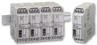
## **Switch Mode Power Supply S8TS**

## **Block-type Switch mode Power Supply That Mounts to DIN-rail**

- Power supply range of 60 to 240 W available with just one model (24-V models).

- Easy creation of multi-power supply configurations with different output power supplies connected together (24-V, 12-V, and 5-V models).

- Improve power supply system reliability by creating N+1 redundant systems (24-V and 12-V models).

- Approved by UL/CSA standards, EN60950 (IEC 950), and VDE 0160.

## **Model Number Structure**

## ■ **Model Number Legend**

## **S8TS-** @@@@@@ **-** @@

**1         2    3       4**

**1. Capacity 2. Output Voltage 3. Structure 4. Bus Line Connectors** 060: 60 W 24: 24 V None: Screw terminals None: Basic Block only 030: 30 W 12: 12 V F: Connector E1: S8T-BUS01 and 025: 25 W 05: 5 V terminals S8T-BUS02 included

## **Orderin Information g**

## ■ **Basic Block**

|■**Basic Block**||||||
|---|---|---|---|---|---|
|**Output voltage**|**Output current**|**Screw terminal type**||**Connector terminal type**<br>**(See note 3.)**||
|||**With Bus Line**<br>**Connectors**<br>**(See note 1.)**|**Without Bus Line**<br>**Connectors**<br>**(See note 2.)**|**With Bus Line**<br>**Connectors**<br>**(See note 1.)**|**Without Bus Line**<br>**Connectors**<br>**(See note 2.)**|
|24 V|2.5 A|S8TS-06024-E1|S8TS-06024|S8TS-06024F-E1|S8TS-06024F|
|12 V|2.5 A|S8TS-03012-E1|S8TS-03012|S8TS-03012F-E1|S8TS-03012F|
|5 V|5 A|---|S8TS-02505|---|S8TS-02505F|


## ■ **Bus Line Connector**

|■**Bus Line Connector**|||
|---|---|---|
|**Type**|**Number of Connectors**|**Model number**|
|AC line + DC line bus<br>(For parallel operation)|1 Connector|S8T-BUS01|
||10 Connectors (See note 4.)|S8T-BUS11|
|AC line bus<br>(For series operation or isolated operation)|1 Connector|S8T-BUS02|
||10 Connectors (See note 5.)|S8T-BUS12|


- **Note 1.** One S8T-BUS01 Connector and one S8T-BUS02 Connector are included as accessories.

   **2.** Bus Line Connectors are ordered separately if necessary.

   **3.** Attached connectors: 2ESDPLM-05P (for output terminal) and 3ESDPLM-03P (for input terminal) made by DINKLE ENTERPRISE.

   **4.** One package contains 10 S8T-BUS01 Connectors.

   **5.** One package contains 10 S8T-BUS02 Connectors.

Switch Mode Power Supply **S8TS**

B-53

**S ecifications p**

## ■ **Ratings/Characteristics**

## **24/12-V Models (Basic Block: S8TS-06024** @ **/S8TS-03012** @)

||**Item**||**Single operation**|**Parallel operation**|
|---|---|---|---|---|
|Efficiency|||24-V models: 75% min.; 12-V models: 70% min. (with rated input, 100% load)||
|Input|Voltage||100 to 240 VAC (85 to 264 VAC)||
||Frequency||50/60 Hz (47 to 63 Hz)||
||Current|100 V input|24-V models: 1.0 A max.<br>12-V models: 0.7 A max.|24-V models: 1.0 A×(No. of Blocks) max.<br>12-V models: 0.7 A×(No. of Blocks) max.|
|||200 V input|24-V models: 0.5 A max.<br>12-V models: 0.4 A max.|24-V models: 0.5 A×(No. of Blocks) max.<br>12-V models: 0.4 A×(No. of Blocks) max.|
||Power factor||24-V models: 0.9 min.; 12-V models: 0.8 min. (with rated input, 100% load) (See note 3.)||
||Leakage current|100 V input|0.35 mA max.|0.35 mA×(No. of Blocks) max.|
|||240 V input|0.7 mA max.|0.7 mA×(No. of Blocks) max.|
||Inrush current<br>(25°C, cold start)<br>(See note 4.)|100 V input|25 A max.|25 A×(No. of Blocks) max.|
|||200 V input|50 A max.|50 A×(No. of Blocks) max.|
|Output (See<br>note 3.)|Voltage adjustment range||24-V models: 22 to 28 V<br>12-V models: 12 V±10% (with V.ADJ) (See note 1.)||
||Ripple||2% (p-p) max.||
||Input variation influence||0.5% max. (with 85 to 264 VAC input, 100% load)||
||Load variation influence||2% max. (with rated input, 10% to 100% load)|3% max. (with rated input, 10% to 100% load)|
||Temperature variation influence||0.05%/°C max. (with rated input and output)||
||Startup time (See note 4.)||1,000 ms max.||
||Hold time (See note 4.)||20 ms min. (with 100/200 VAC, rated input)||
|Additional<br>functions|Overcurrent protection (See note 4.)||105% to 125% of rated load current, inverted L drop<br>type, automatic reset|100% to 125% of rated load current inverted L drop<br>type, automatic reset|
||Overvoltage protection (See note 4.)||Yes||
||Parallel operation||Yes, 4 Blocks max.||
||N+1 redundant system||Yes, 5 Blocks max.||
||Series operation||Yes||
||Undervoltage indicator (See note 4.)||Yes (color: red)||
||Undervoltage detection output (See<br>note 4.)||Yes (open collector output), 30 VDC max., 50 mA max.||
|Other|Ambient operating temperature (See<br>note 4.)||Operating:<br>Refer to the derating curve in_Engineering Data._<br>Storage:<br>−25 to 65°C (with no icing or condensation)||
||Ambient humidity||Operating: 25% to 85%; Storage: 25% to 90%||
||Dielectric strength||3.0 kVAC, 50/60 Hz for 1 minute (between all inputs and all outputs; detection current: 20 mA)||
||||2.0 kVAC, 50/60 Hz for 1 minute (between all inputs and GR terminal; detection current: 20 mA)||
||||1.0 kVAC for 1 minute (between all outputs and GR terminal; detection current: 20 mA)||
||Insulation resistance||100 MΩmin. (between all outputs and all inputs, and between all outputs and GR terminal) at 500 VDC||
||Vibration resistance||10 to 55 Hz, 0.375-mm single amplitude for 2 h each in X, Y, and Z directions||
||Shock resistance||150 m/s2, 3 times each in±X,±Y, and±Z directions||
||Output indicator||Yes (color: green)||
||Electromagnetic interference||Conforms to FCC Class A, EN50081-1||
||EMI||Conforms to EN50081-1/1992||
||Power factor correction||Conforms to EN61000-3-2, EN61000-3-2 A14||
||EMS||Conforms to EN61000-6-2/1999||
||Approved standards||UL:<br>508 (Listing; Class 2: Per UL1310), 1950, 1604 (Class I, Division 2, Groups A, B, C, D<br>Hazardous Locations))<br>cUL:<br>CSA C22.2 No.14, No.213 (Class I, Division 2, Groups A, B, C, D<br>Hazardous Locations), No. 950 (Class 2) (See note 2.)<br>EN/VDE:<br>EN50178 (=VDE0160), 60950 (=VDE0806)||
||Weight||450 g max.|450 g×(No. of Blocks) max.|


- **Note 1.** Refer to page B-59 for details on adjusting the output voltage for parallel operation. If set to less than −10%, the undervoltage detection function may operate. Ensure that the output capacity and output current after adjustment do not exceed the rated output capacity and rated output current respectively.

   **2.** Class 2 approval does not apply to parallel operation.

   **3.** The output current is specified at power output terminals.

   **4.** Refer to the explanations of functions on page B-56 for details.

   **5.** Be sure to mount End Plates (PFP-M) on both ends of the Power Supply.

Switch Mode Power Supply **S8TS**

B-54

## **5-V Models (Basic Block: S8TS-02505** @ **)**

|**Item**|**Item**||**Single operation**|
|---|---|---|---|
|Efficiency (typical)|||62% min. (with rated input, 100% load)|
|Input|Voltage||100 to 240 VAC (85 to 264 VAC)|
||Frequency||50/60 Hz (47 to 63 Hz)|
||Current|100 V input|0.7 A max.|
|||200 V input|0.4 A max.|
||Power factor||0.8 min. (with rated input, 100% load)|
||Leakage current|100 V input|0.35 mA max.|
|||240 V input|0.7 mA max.|
||Inrush current<br>(25°C, cold start)<br>(See note 2.)|100 V input|25 A max.|
|||200 V input|50 A max.|
|Output (See<br>note 2.)|Voltage adjustment range||5 V±10% (with V. ADJ) (See note 1.)|
||Ripple||2% (p-p) max.|
||Input variation influence||0.5% max. (with 85 to 264 VAC input, 100% load)|
||Temperature variation influence||0.05%/°C max. (with rated input and output)|
||Load variation influence||1.5% max. (with rated input, 10% to 100% load)|
||Startup time (See note 3.)||1,000 ms max.|
||Hold time (See note 3.)||20 ms min. (with 100/200 VAC, rated input)|
|Additional<br>functions|Overcurrent protection (See note 3.)||105% to 125% of rated load current, inverted L drop type, automatic reset|
||Overvoltage protection (See note 3.)||Yes|
||Parallel operation||No|
||N+1 redundant system||No|
||Series operation||Yes (with the external diode)|
||Undervoltage indicator (See note 3.)||Yes (color: red)|
||Undervoltage detection output (See note<br>3.)||Yes (open collector output), 30 VDC max., 50 mA max.|
|Other|Ambient operating temperature (See note<br>3.)||Operating:<br>Refer to the derating curve in_Engineering Data._<br>Storage:<br>−25 to 65°C (with no icing or condensation)|
||Ambient humidity||Operating: 25% to 85%, Storage: 25% to 90%|
||Dielectric strength||3.0 kVAC, 50/60 Hz for 1 minute (between all inputs and all outputs; detection current: 20 mA)|
||||2.0 kVAC, 50/60 Hz for 1 minute (between all inputs and GR terminal; detection current: 20 mA)|
||||1.0 kVAC for 1 minute (between all outputs and GR terminal; detection current: 20 mA)|
||Insulation resistance||100 MΩmin. (between all outputs and all inputs, and between all outputs and GR terminal) at 500 VDC|
||Vibration resistance||10 to 55 Hz, 0.375-mm single amplitude for 2 h each in X, Y, and Z directions|
||Shock resistance||150 m/s2, 3 times each in±X,±Y, and±Z directions|
||Output indicator||Yes (color: green)|
||Electromagnetic interference||Conforms to FCC Class A, EN50081-1|
||EMI||Conforms to EN50081-1/1992|
||Power factor correction||Conforms to EN61000-3-2, EN61000-3-2A14|
||EMS||Conforms to EN61000-6-2/1999|
||Approved standards||UL:<br>508 (Listing), 1950, 1604 (Class I, Division 2, Groups A, B, C, D<br>Hazardous Locations)<br>cUL:<br>CSA C22.2 No.14, No.213 (Class I, Division 2, Groups A, B, C, D<br>Hazardous Locations), No. 950<br>EN/VDE:<br>EN50178 (=VDE0160), 60950 (=VDE0806)|
||Weight||450 g max.|


- **Note 1.** If set to less than −10%, the undervoltage detection function may operate. Ensure that the output capacity and output current after adjustment do not exceed the rated output capacity and rated output current respectively.

   **2.** The output current is specified at power output terminals.

   **3.** Refer to the explanations of functions on page B-56 for details.

   **4.** Be sure to mount End Plates (PFP-M) on both ends of the Power Supply.

## ■ **Reference Value**

|**Item**|**Value**|**Definition**|
|---|---|---|
|Reliability (MTBF)|250,000 hrs min.|MTBF stands for Mean Time Between Failures, which is calculated according to the probability of acci-<br>dental device failures, and indicates reliability of devices. Therefore, it does not necessarily represent the<br>life of the product.|
|Life expectancy|10 yrs min.|The life expectancy indicates average operating hours under the ambient temperature of 40°C and a load<br>rate of 50%. Normally this is determined by the life expectancy of the built-in aluminum electrolytic ca-<br>pacitor.|


Switch Mode Power Supply **S8TS**

B-55
Updated at June 4, 2026
With a legacy spanning over 80 years, Omron Industrial Automation is a globally recognized leader in the manufacture of advanced industrial control and automation components. Renowned for their reliability and engineering excellence, Omron delivers comprehensive solutions that enhance efficiency, machine safety, and precision across a wide range of manufacturing environments. Our extensive portfolio of Omron products is heavily focused on their industry-leading sensing and switching technologies. We offer a vast selection of sensors, excelling specifically in high-performance proximity sensors, light sensors, and temperature sensors. Complementing this range are robust switching solutions, featuring a deep inventory of power relays, solid-state relays, safety relays, and essential relay accessories designed for demanding operational requirements. Beyond sensing and switching, Omron is highly regarded for its precision automation and process control equipment. Our selection features highly accurate temperature controllers, versatile process controllers, and sophisticated panel displays and instrumentation. To support these fundamental systems, we also supply dependable Omron power supplies, notably AC/DC converters, alongside vital connectivity components like DIN rail terminal blocks to ensure secure, efficient, and complete industrial setups.
About Novapart
Novapart is a B2B electronic component broker specialising in stock shortages and cost reduction. We source hard-to-find parts and identify compliant alternatives across a catalogue of 410,000+ components from 500+ manufacturers.
Learn more →Stock Shortage Specialist
When a component is unavailable, discontinued or has an unacceptable lead time, we tap into our network of vetted European and Asian distributors to source what you need — without compromising on quality or traceability.
Request a quote →Compliant Alternatives
We identify pin-to-pin, electrically equivalent substitutes that meet the same certifications (RoHS, AEC-Q100, REACH) as your original specification — validated against datasheets, not just part numbers. Often at a lower cost.
BOM Analysis service →