
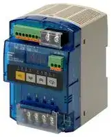


S8M-CP04-RS
Digital Multicircuit Protector, RS232, 24 VDC
- Manufacturer: OMRON INDUSTRIAL AUTOMATION
- Product type: Controller Accessories
- SVHC: To Be Advised
- Product Range: S Series
- Current Rating: 4A
| Delivery and price | |
|---|---|
| Units per pack | 1 |
| Price | 309.06 € |
| Current stock | 10+ |
| Lead time | 30 days |
**Digital Multicircuit Protector S8M**

## **Complete Flexible DC Circuit Protector That Has a Wide Array of Displays, Alarm Outputs, and Other Digital Functions.**

- Four circuit protectors in one package

- Simple setting of current tripping values for each branch outputs in 0.1-A units

- Startup and shutdown sequence control

- Display and alarm functions (Input voltage, output current, run time, and over-temperature)

- Outputs conform to UL Class 2 (at 24 VDC, S8M-CP04-RS only)

- DIN Rail mounting

- Free Support Tool available

**Note:** Refer to _Precautions for Safe Use_ on page 20.

## **Model Number Structure**

## ■ **Model Number Legend**

**Note:** Not all combinations are possible. Please refer to the list of models in _Ordering Information_ below.

## **S8M-CP04-** @@

**1 2**

## **1. Communications**

None: Not supported R: Supported (RS-232)

## **2. UL Class 2 Output (at 24 VDC)**

None: Not compliant S: Compliant

## **Orderin Information g**

**Note:** For details on normal stock models, contact your nearest OMRON representative.

|**Communications**|**UL Class 2 output**|**Model number**|
|---|---|---|
|None|Not compliant|S8M-CP04|
|Supported (RS-232C)|Not compliant|S8M-CP04-R|
||Compliant|S8M-CP04-RS|


## **Recommended Power Supplies**

|**Series name**|**Model number**|
|---|---|
|S8VS|S8VS-06024@@|
||S8VS-09024@@|
||S8VS-12024@@|
||S8VS-18024@@|
||S8VS-24024@@|
|S8VM|S8VM-05024@@|
||S8VM-10024@@|
||S8VM-15024@@|
||S8VM-30024C|
||S8VM-60024C|


**Note:** When selecting the power supply, be sure to include the internal power consumption of the S8M (approx. 10 W) and not just the power consumption of the load.

This Datasheet describes only the minimum setting operations required when using the S8M for the first time. Refer to the _S8M User's Manual_ (Cat. No. Z241), when making further settings.

Digital Multicircuit Protector **S8M**

1

## **S ecifications p**

## ■ **Ratings/Characteristics**

|**Item**<br>**Model**|**Item**<br>**Model**|**Item**<br>**Model**|**S8M-CP04**|**S8M-CP04-R**|**S8M-CP04-RS**|
|---|---|---|---|---|---|
|**Number of branches**|||4|||
|**I/O**<br>**character-**<br>**istics**|**Rated input voltage**||24 VDC (19.2 to 26.4 VDC)|||
||**Allowable input current**||17.0 A max.||16.0 A max.|
||**Maximum tripping output current**<br>**(per branch output)**||4.0 A||3.8 A|
||**Internal voltage drop (See note 1.)**||0.5 VDC max. (at 4.0 A)||0.7 VDC max. (at 3.8 A)|
||**Output leakage current**||10 mA max.|||
||**Power**<br>**consump-**<br>**tion**<br>**(See note 2.)**|**4 branches output,**<br>**normal operation**|10 W max. (at 4.0 A)||15 W max. (at 3.8 A)|
|||**4 branches output,**<br>**tripping operation**|3 W max.|||
|**Functions **|**Tripping**|**Abnormal voltage**<br>**tripping**|28.8 V (fixed), tripping alarm output|||
|||**Abnormal current**<br>**tripping**|Setting range: 0.5 to 4.0 A (in 0.1-A units), tripping alarm<br>output||Setting range: 0.5 to 3.8 A (in 0.1-A<br>units), trippingalarm output|
|||**Tripping alarm out-**<br>**put**|Transistor output<br>30 VDC max., 50 mA max., leakage current: 0.1 mA max., residual voltage: 2 V max.|||
||**Alarms**|**Overvoltage**|Settingrange: 20.0 to 28.8 V(in 0.1-V units), alarm output|||
|||**Undervoltage**|Settingrange: 18.0 to 26.4 V(in 0.1-V units), alarm output|||
|||**Overcurrent**|Setting range: 0.5 to 4.0 A (in 0.1-A units), alarm output||Setting range: 0.5 to 3.8 A (in 0.1-A<br>units), alarm output|
|||**Run time**|Setting range: 0.0 to 99.9 kh (in 0.1-kh units), alarm output<br>(The alarm output is disabled if the time is set to 0.0 kh.)|||
|||**Alarm output**|Transistor output<br>30 VDC max., 50 mA max., leakage current: 0.1 mA max., residual voltage: 2 V max.|||
||**Temperature**|**Temperature**|Settingrange: 25 to 80°C, over-temperature output|||
|||**Over-temperature**<br>**output**|Transistor output<br>30 VDC max., 50 mA max., leakage current: 0.1 mA max., residual voltage: 2 V max.|||
||**Display**|**Input voltage**|Display range: 17.0 to 30.0 V<br>Displayaccuracy: 2% rdg ±1 digit max.|||
|||**Output current**|Branch output display range:<br>0.0 to 4.0 A<br>Peak output current display range:0.0 to 10.0 A<br>Total current display range:<br>0.0 to 40.0 A<br>Displayaccuracy:<br>5% FS(4 A) ±1 digit max.|||
|||**Run time**|Display range:<br>0.0 to 99.9 kh<br>Displayaccuracy: 2% rdg ±1 digit max.|||
|||**Temperature**|Display range:<br>−10 to 100°C<br>Display accuracy: 2°C±1 digit max.|||
||**External tripping input**||19.2 to 30 VDC, minimum signal width: 10 ms, tripping within 20 ms of input|||
||**Startup sequence**||Can be enabled/disabled for each branch output, setting range: 0.0 to 99.9 s in 0.1-s units.|||
||**Shutdown sequence**||Can be enabled/disabled for each branch output, setting range: 0.0 to 99.9 s in 0.1-s units.|||
||**Communications**||None|Supported (RS-232C)||
||**Sampling period**||1 ms|||


Digital Multicircuit Protector **S8M**

2

|**Item**|**Model**|**Model**|**S8M-CP04**|**S8M-CP04-R**|**S8M-CP04-RS**|
|---|---|---|---|---|---|
|**Other**|**Ambient operating temperature**||Refer to the deratingcurve in_Engineering Data_ (with no condensation or icing) (See note 3.)|||
||**Storage temperature**||−25 to 65°C|||
||**Ambient operating humidity**||25% to 85%(storage humidity: 25% to 90%)|||
||**Dielectric strength**||1.0 kVAC for 1 min (between all charged sections and all non-charged sections; detection cur-<br>rent: 20 mA)<br>500 VAC for 1 min (between all I/O and I/O signals/communications; detection current: 20 mA)<br>500 VAC for 1 min (between all I/O signals and communications; detection current: 20 mA)<br>500 VAC for 1 min(between input signals and all output signals; detection current: 20 mA)|||
||**Insulation resistance**||100 MΩmin. (between all charged sections and all non-charged sections) at 500 VDC<br>100 MΩmin. (between all I/O and I/O signals/communications) at 500 VDC<br>100 MΩmin. (between all I/O signals and communications) at 500 VDC<br>100 MΩmin.(between input signals and all output signals)at 500 VDC|||
||**Vibration resistance**||10 to 55 Hz, 0.375-mm single amplitude for 2 h each in X, Y, and Z directions|||
||**Shock resistance**||150 m/s2, 3 times each in±X,±Y, and±Z directions|||
||**EMI**|**Conducted**<br>**Emission**|Conforms to EN 61204-3 Class B|||
|||**Radiated Emission**|Conforms to EN 61204-3 Class B|||
||**EMS**||Conforms to EN 61204-3 High severitylevels|||
||**Approved standards**||UL:<br>UL 508 (Listing), UL 60950-1<br>cUL:<br>CSA C22.2 No. 107.1<br>cUR:<br>CSA No. 60950-1<br>EN/VDE:EN 50178 (= VDE 0160), EN 60950-1<br>(= VDE 0805 Teil 1)||UL:<br>UL 508 (Listing, Class 2:<br>Per UL 1310), UL60950-1<br>cUL:<br>CSA C22.2 No. 107.1<br>cUR:<br>CSA No. 60950-1<br>EN/VDE:EN 50178<br>(= VDE 0160),<br>EN 60950-1<br>(= VDE 0805 Teil 1)|
||**Weight**||400 g max.|||


- **Note: 1.** A voltage drop will occur in the S8M. Consider the voltage drop at the output.

   **2.** When selecting the power supply, be sure to include the internal power consumption of the S8M (approx. 10 W) and not just the power consumption of the load.

   **3.** Refer to _Engineering Data_ on page 6 for details.

Digital Multicircuit Protector **S8M**

3

## **Connections**

## ■ **Block Diagrams**

**==> picture [507 x 318] intentionally omitted <==**

**----- Start of picture text -----**<br>
S8M-CP04-R/-RS only<br>S8M-CP04-RS only Cutoff Current-detection Current-detection Cutoff<br>circuit resistor Thermal resistor circuit Fuse<br>fuse<br>+V +V<br>detectionVoltage Displaycircuit Switch Temperaturedetection DC branch output 1<br>Current-  −V<br>limiting<br>DC input circuit<br>power supply<br>Power supplycircuit Processingcircuit Cutoffcircuit Current-detectionresistor Thermal Current-detectionresistor Cutoffcircuit Fuse<br>fuse<br>+V<br>DC branch output 2<br>Current-  −V<br>Communi-cationsterminalsRS-232C SGRDSD Communicationscircuit limitingcircuit<br>Cutoff Current-detection Current-detection Cutoff<br>circuit resistor Thermal resistor circuit Fuse<br>fuse<br>Tripping alarm +V<br>output<br>DC branch output 3<br>Alarm output Current-  −V<br>limiting<br>Over- circuit<br>temperature<br>output<br>Cutoff Current-detection Current-detection Cutoff<br>External circuit resistor Thermal resistor circuit Fuse<br>tripping input fuse<br>+V<br>DC branch output 4<br>Current-  −V<br>limiting<br>circuit<br>−V<br>**----- End of picture text -----**<br>


Digital Multicircuit Protector **S8M**

4

**Construction and Nomenclature**

## ■ **Nomenclature**

**==> picture [189 x 212] intentionally omitted <==**

**----- Start of picture text -----**<br>
4   5   6   7<br>1<br>14<br>8<br>9<br>13 10<br>12 11<br>3<br>2<br>Note:  The S8M-CP04-RS is shown above.<br>**----- End of picture text -----**<br>


**==> picture [156 x 142] intentionally omitted <==**

**----- Start of picture text -----**<br>
4 Tripping alarm output (TRP)<br>5 Alarm output (ALM)<br>6 Over-temperature output (TMP)<br>7 External tripping input (TRG)<br>Internal circuit configuration<br>**----- End of picture text -----**<br>


|**e**||||
|---|---|---|---|
|**No.**|**Name**||**Function**|
|1|Power Input Terminals<br>(+V),(−V)||Connect to the input line.|
|2<br>3|Branch Output<br>Terminals (+V), (−V)<br>Status Indicators<br>||Connect to the load lines.<br>Up to four branch outputs can be<br>connected.<br>Indicate the connection and cutoff<br>|
||(Red, Green)||status for each branch output.<br>Cut off: Red, Connected: Green (See<br>note 1.)|
|4<br>5|Tripping Alarm Output<br>(+,−)<br>Alarm Output (+,−)||Output (transistor: OFF) when the<br>error tripping operation functions.<br>(See note 2.)<br>Output (transistor: OFF) when a set|
|6|<br>Over-temperature<br>Output (+−)||<br>value for alarm detection is exceeded.<br>(See note 2.)<br>Output (transistor: OFF) when a set<br>value for over-temperature detection|
|7|,<br>External Tripping Input<br>(+,−)||<br>is exceeded.(See note 2.)<br>The tripping operation can be<br>executed with an externally input<br>signal.|
|8|Seven-segment Display<br>(Red)||Displays measured values and set<br>values.|
|9|Unit Indicators<br>(Orange)|V|Lit when the input voltage is being<br>displayed.|
|||A|Lit when the output current is being<br>displayed.<br>Flashes when the peak output current<br>is beingdisplayed.|
|||kh|Lit when the run time is being<br>displayed.|
|||°C|Lit when the temperature is being<br>displayed.|
|||s|Lit when settingthe sequence time.|
|||1 to 4|Lit or flashing when displaying branch<br>output information.(See note 3.)|
|10|Mode Key||Used to change the parameter being<br>displayed or to reset the peak hold<br>current value.|
|11|Up Key||Used to move to different setting<br>modes or to increase a set value.|
|12|Down Key||Used to move to different setting<br>modes or to decrease a set value.|
|13|Reset Key (RST)||Used when connecting branch<br>outputs for tripping operation. (See<br>note 4.)|
|14|Communications<br>Terminals(RD, SD, SG)||Connect to the communications lines<br>(RS-232C).(See note 5.)|


- **Note: 1.** For detailed display methods, refer to _Status Indicators_ on page 13.

   **2.** Configured from independent circuits, and either sinking or sourcing applications are possible.

   **3.** Indicators 1 to 4 will not light except when the current is being displayed.

   **4.** Press for at least 3 s to enable operation.

   **5.** Except for the S8M-CP04.

Digital Multicircuit Protector **S8M**

5

**En ineerin Data g g**

## ■ **Derating Curve**

**==> picture [160 x 143] intentionally omitted <==**

**----- Start of picture text -----**<br>
120 S8M-CP04, S8M-CP04-R: Maximum output current 4.0 A<br>S8M-CP04-RS: Maximum output current 3.8 A<br>100 1<br>80<br>60<br>40<br>20<br>0<br>−20 −10 0 10 20 30 40 50 60 70<br>Maximum applied current for any one branch output (%)<br>**----- End of picture text -----**<br>


## **Derating Curve of the S8M**

The ambient temperature that S8M can be operating is limited by the maximum output current of one branch terminal on ordinary current condition.

Ambient temperature (°C)

- **Note: 1.** Internal parts may occasionally be deteriorated or damaged. Do not use the S8M in areas outside the derating curve (i.e., in the area shown by shading A in the above graph).

   **2.** If there is a derating problem, use forced air cooling.

## ■ **Abnormal Current Tripping**

## **Standard Detection**

## **S8M-CP04/S8M-CP04-R**

## **S8M-CP04-RS**

**==> picture [498 x 142] intentionally omitted <==**

**----- Start of picture text -----**<br>
Time (ms) Time (ms)<br>Characteristics when steady Characteristics when steady<br>Setting Setting<br>range range<br>Current limited by Current limited by<br>Tripping region internal circuit Tripping region internal circuit<br>100 100<br>20 20<br>0.5 4 6 12 Current (A) 0.5 3.8 6 12 Current (A)<br>**----- End of picture text -----**<br>


## **Instantaneous Detection**

## **S8M-CP04/S8M-CP04-R**

## **S8M-CP04-RS**

**==> picture [500 x 141] intentionally omitted <==**

**----- Start of picture text -----**<br>
Time (ms) Time (ms)<br>Characteristics when steady Characteristics when steady<br>Setting Setting<br>range range<br>Current limited by Current limited by<br>internal circuit internal circuit<br>Tripping region Tripping region<br>20 20<br>0.5 4 12 Current (A) 0.5 3.8 12 Current (A)<br>**----- End of picture text -----**<br>


Digital Multicircuit Protector **S8M**

6

## ■ **Mounting**

## **Standard Mounting**

## **Correct**

## **Face-up Mounting**

## **Incorrect**

**==> picture [247 x 87] intentionally omitted <==**

- **Note: 1.** Improper mounting will interfere with heat dissipation and may occasionally result in deterioration or damage of internal parts. Do not use any mounting method other than the standard one.

   **2.** Take adequate measures to ensure proper heat dissipation to increase the long-term reliability of the S8M.

   **3.** Install the S8M so that the air flow circulates around it, because the S8M is designed to radiate heat by means of natural air flow.

## **Functions**

## ■ **Functions**

|■**Functions**||||
|---|---|---|---|
|**Alarm**|**Alarm output**|**Output status**|**Alarm display**|
|Abnormal voltage tripping|TRP output: OFF<br>(normally ON)|All branch outputs cut off.|A10|
|Abnormal current tripping|TRP output: OFF<br>(normally ON)|Relevant branch output cut<br>off.|A11|
|Overvoltage alarm|ALM output: OFF<br>(normally ON)|ON|A20|
|Undervoltage alarm|ALM output: OFF<br>(normally ON)|ON|A21|
|Overcurrent alarm|ALM output: OFF<br>(normally ON)|ON|A22|
|Run time alarm|ALM output: OFF<br>(normally ON)|ON|A23|
|Over-temperature output|TMP output: OFF<br>(normally ON)|ON|A30|


Digital Multicircuit Protector **S8M**

7

## ■ **Tripping Functions**

|**Function**|**Operation**|
|---|---|
|Abnormal voltage tripping<br>Refer to_Chart 1_.<br>(See notes 2, 3 and 4.)|The input voltage is monitored and all branch outputs are cut off if the detection voltage is reached. Notification of the<br>status is provided using the alarm display and the tripping alarm output (TRP).<br>The alarm display will alternate between the voltage and the alarm code (A10). The primary voltage is measured at<br>the input terminals.<br>Detection voltage: 28.8 V(fixed)|
|Abnormal current tripping<br>Refer to_Chart 2_.<br>(See notes 2 and 3.)|The output current is monitored and the branch output that is abnormal is cut off if the preset current is reached.<br>Notification of the status is provided using the alarm display and the tripping alarm output (TRP).<br>The alarm display will alternate between the current and the alarm code (A11).<br>Abnormal current detection setting range: 0.5 to 4.0 A (S8M-CP04-RS: 0.5 to 0.38 A) in 0.1-A units.<br>Either of two abnormal current tripping types can be set.<br>Standard detection: Tripping within 100 ms. (If a current exceeding the set value flows for 80 ms or more, it is detected<br>as an abnormal current and power is cut off within 20 ms.)<br>Instantaneous detection: Tripping within 20 ms. (If a current exceeding the set value flows for 10 ms or more, it is<br>detected as an abnormal current and power is cut off within 10 ms.)<br>(Refer topage 14 for the setting procedure.)|
|Tripping by external signal<br>(See note 2.)|The output can be cut off by inputting a voltage to the external tripping input (TRG terminal). If a shutdown sequence<br>has been set, outputs will be cut off according to the shutdown sequence. (Refer to page 14 for information on the<br>shutdown sequence.)<br>External input signal width: 10 ms min.<br>External tripping enable/disable setting: Enabled<br>Input signal levels<br>High level: 19.2 to 30 VDC<br>Low level: 0 to 2.5 VDC<br>Tripping can also be performed by using communications (S8M-CP04-R/RS only).<br>Refer to the_S8M User’s Manual_ (Cat. No. Z241)for information on trippingusingcommunications.|


- **Note: 1.** Two abnormal current tripping types are supported depending on the tripping current characteristics: Standard detection and instantaneous detection. Select the required tripping type.

   **2.** Outputs are cut off using semiconductor relays and electrical insulation is not provided.

   **3.** The output will remain OFF and the alarm display and alarm output will not be cleared even if power is restored. The S8M must be reset to restore operation. (Refer to _List of Alarms_ on page 16 for details.)

   **4.** The voltage at the power input terminals is monitored to detect abnormal voltages. To confirm correct output voltages, measure the voltages at the branch output terminals.

## **Chart 1: Operation Timing**

**==> picture [234 x 172] intentionally omitted <==**

**----- Start of picture text -----**<br>
28.8 V (Abnormal voltage tripping) (Fixed)<br>25 V (Overvoltage alarm) (Settable)<br>24 V (Rated)<br>18 V (Undervoltage alarm) (Settable)<br>0<br>100 ms 100 ms t<br>Alarm display A21 A20 A10<br>Alarm output<br>(See note.)<br>20 ms<br>Tripping alarm output<br>(See note.)<br>3 s<br>Reset<br>**----- End of picture text -----**<br>


**Note:** The alarm and tripping alarm output are both transistor outputs. It is normally ON and turns OFF when an alarm is detected.

## **Chart 2: Operation Timing**

**==> picture [216 x 201] intentionally omitted <==**

**----- Start of picture text -----**<br>
4.0 A (Settable)<br>(Abnormal current tripping)<br>3.5 A (Settable)<br>(Overcurrent alarm)<br>3.0 A<br>(Normal current)<br>0<br> 20 ms t<br> (Instantaneous) 100 ms<br>Alarm display A22  (Standard) A22 A11<br>Alarm output<br>(See note.) Within 20 ms for instantaneous<br>detection and 100 ms for standard<br>Tripping alarm output detection (depends on tripping type).<br>(See note.)<br>3 s<br>Reset<br>Note:  The alarm and tripping alarm output are both transistor outputs.<br>It is normally ON and turns OFF when an alarm is detected.<br>**----- End of picture text -----**<br>


Digital Multicircuit Protector **S8M**

8

## ■ **Alarm Functions**

|**Function**|**Operation**|
|---|---|
|Overvoltage alarm<br>(Refer to_Chart 1_.)<br>(See notes 1 and 2.)<br> <br> <br> <br> <br>|The voltage is monitored and notification is provided using the alarm display and output (ALM) if the preset<br>voltage is exceeded for more than 100 ms. The alarm display will alternate between the voltage and the alarm<br>code (A20). The primary voltage is measured at the input terminals.<br>Overvoltage alarm setting range: 20.0 to 28.8 V in 0.1-V units.<br>(Refer topage 14 for the setting procedure.)|
|Overcurrent alarm<br>(Refer to_Chart 2_.)<br>(See note 1.)<br> <br> <br> <br> <br> <br> <br> <br>|Each branch output current is monitored and notification is provided using the alarm display and output (ALM) if<br>the preset value is reached.<br>The alarm display will alternate between the current and the alarm code (A22).<br>Overcurrent alarm setting range: 0.5 to 4.0 A (S8M-CP04-RS: 0.5 to 0.38 A) in 0.1-A units.<br>Either of two tripping types can be set.<br>Standard detection: An alarm is output if the current exceeds the set value for 80 ms or longer.<br>Instantaneous detection: An alarm is output if the current exceeds the set value for 10 ms or longer.<br>(Refer topage 14 for the setting procedure.)|
|Undervoltage alarm<br>(Refer to_Chart 1_.)<br>(See notes 1 and 2.)<br> <br> <br> <br> <br>|The voltage is monitored and notification is provided using the alarm display and output (ALM) if the voltage drops<br>below the preset voltage for more than 80 ms. The alarm display will alternate between the voltage and the alarm<br>code (A21). The primary voltage is measured at the input terminals.<br>Undervoltage alarm setting range: 18.0 to 26.4 V in 0.1-V units.<br>(Refer to page 14 for the setting procedure.)|
|Run time alarm<br>(Refer to_Chart 3_.)<br>(See note 1.)<br> <br> <br> <br> <br> <br>|The time that the power is turned ON is calculated as the S8M run time and notification is provided using the<br>alarm display and output (ALM) if the preset time is reached. The alarm display will alternate between the run<br>time and the alarm code (A23).<br>Display range: 0.0 to 99.9 kh in 0.1-kh units.<br>Run time setting range: 0.0 to 99.9 kh in 0.1-kh units.<br>(Refer to page 14 for the setting procedure.)|
|Over-temperature output<br>(Refer to_Chart 4_.)<br>(See note 1.)<br> <br> <br> <br> <br> <br> <br> <br> <br> <br>|The internal temperature of the S8M is monitored using a built-in temperature sensor and notification is provided<br>using the alarm display and over-temperature output (TMP) if the preset temperature is exceeded for more than<br>1 s. The alarm display will alternate between the temperature and the alarm code (A30). The over-temperature<br>output is convenient for control operations, such as operating a cooling fan to suppress temperature increased in<br>the control panel.<br>Note: The alarm display and over-temperature output are automatically cleared if the temperature falls below the<br>set temperature.<br>Display range:−10 to 100°C in 1°C units.<br>Temperature setting range: 25 to 80°C in 1°C units.<br>(Refer to page 14 for the setting procedure.)|


**Note: 1.** Branch outputs are not cut off for the alarm functions.

**2.** The voltage at the power input terminals is monitored to detect abnormal voltages. To confirm correct output voltages, measure the voltages at the branch output terminals.

## **Chart 3: Operation Timing**

**==> picture [191 x 172] intentionally omitted <==**

**----- Start of picture text -----**<br>
Run time<br>50.0 kh (Settable)<br>0<br>t<br>Power ON<br>Alarm display A23<br>Alarm output<br>(See note.)<br>Run time cleared<br>**----- End of picture text -----**<br>


## **Chart 4: Operation Timing**

**==> picture [192 x 132] intentionally omitted <==**

**----- Start of picture text -----**<br>
Temperature<br>50°C (Settable)<br>0<br>t<br>Alarm display A30 A30 A30<br>Over-temperature<br>output (See note.)<br>**----- End of picture text -----**<br>


**Note:** The alarm display and over-temperature output are automatically cleared (with hysteresis). (Refer to page 16.) The over-temperature output is a transistor output. It is normally ON and turns OFF when an alarm is detected.

**Note:** The alarm output is a transistor output. It is normally ON and turns OFF when an alarm is detected.

Digital Multicircuit Protector **S8M**

9

## ■ **Other Functions**

|**Function**|**Operation**|
|---|---|
|Startup sequence<br>(Refer to_Chart 5_.)|The connection timing for branch outputs 1 to 4 can be set individually to offset the connection timing of load<br>devices. Creating time delays between starting loads enables safe load operation. It also reduces total inrush<br>current so that power supply capacity can be optimized.<br>Setting range: 0.0 to 99.0 s in 0.1-s units. (See note.)<br>(Refer topage 14 for the setting procedure.)|
|Shutdown sequence<br>(Refer to_Chart 6_.)|The cutoff timing for branch outputs 1 to 4 can be set individually to offset the cutoff timing of load devices for the<br>external tipping input or to enable an emergency stop.<br>Setting range: 0.0 to 99.0 s in 0.1-s units. (See note.)<br>(Refer to page 14 for the setting procedure.)|
|Startup delay|A delay function is provided so that the abnormal current tripping<br>function or overcurrent alarm function will not be triggered by large<br>initial surge currents, e.g., for capacitive loads or lamp loads. The<br>abnormal current tripping function will function once the set time has<br>elapsed.<br>(**Note:**The delay is fixed at 70 ms.)<br>t<br>Current<br>0<br>70 ms: Delay<br>Alarm function disabled<br>for large surge currents<br>at startup.|


**Note:** The sequencing functions are designed for the four branch outputs of one S8M. There is no sync processing between S8M Protectors when more than one S8M is used.

## **Chart 5: Operation Timing**

**==> picture [175 x 155] intentionally omitted <==**

**----- Start of picture text -----**<br>
Power supply voltage<br>Branch output 1 voltage<br>Startup sequence time<br>Branch output 2 voltage<br>Startup sequence time<br>Branch output 3 voltage<br>Startup sequence time<br>Branch output 4 voltage<br>Startup sequence time<br>Self-diagnosis<br>(0.5 s min.)<br>**----- End of picture text -----**<br>


## **Chart 6: Operation Timing**

**==> picture [178 x 169] intentionally omitted <==**

**----- Start of picture text -----**<br>
External tripping input<br>Branch output 1 voltage<br>Shutdown sequence time<br>Branch output 2 voltage<br>Shutdown sequence time<br>Branch output 3 voltage<br>Shutdown sequence time<br>Branch output 4 voltage<br>Shutdown sequence time<br>Within 20 ms<br>Note:  Tripping operation is simultaneous for tripping made for<br>abnormal voltages (28.8 V or higher).<br>**----- End of picture text -----**<br>


Digital Multicircuit Protector **S8M**

10

## ■ **Key Operations and Displays in Each Mode**

**==> picture [513 x 660] intentionally omitted <==**

**----- Start of picture text -----**<br>
Power ON<br>When power was turned  When power was<br>OFF in any mode except  When power was turned  turned OFF in<br>Test Mode ON for the first time Test Mode<br>Run Mode Setting Mode Test Mode<br>(See note.)<br>Input Voltage Abnormal Current<br>Value Setting<br>Display Tripping Value Branch Output 1<br>No key operation for more than 3 s.<br>(See note.)<br>Output Current Abnormal Current Standard/ Connected Cut off<br>Display Tripping Type Instantaneous<br>No key operation for more than 3 s.<br>Peak Output  Clearing selected  Overcurrent<br>Current Display peak output current. Alarm Value Value Setting<br>Or no key operation for  No key operation for more than 3 s. Branch Output 2<br>more than 3 s.<br>Total Current Overcurrent Standard/<br>Display Alarm Type Instantaneous Connected Cut off<br>No key operation for more than 3 s.<br>Undervoltage<br>Run Time Display Alarm Value Value Setting<br>No key operation for more than 3 s.<br>Branch Output 3<br>Temperature Overvoltage<br>Display Alarm Value Value Setting<br>No key operation for more than 3 s. Connected Cut off<br>Run Time<br>Alarm Value Value Setting<br>No key operation for more than 3 s.<br>Over-temperature Branch Output 4<br>Value Setting<br>Output Value<br>No key operation for more than 3 s.<br>Connected Cut off<br>Startup Sequence<br>Time Setting (See note.) Time Setting<br>No key operation for more than 3 s.<br>Shutdown Sequence<br>Time Setting (See note.) Time Setting Cut off all branch outputs<br>(Shutdown Sequence)<br>No key operation for more than 3 s.<br>External Tripping Input Enable/Disable Execute<br>Press for 3 s. Or no key operation for  Setting (See note.) Setting<br>more than 5 s. No key operation for more than 3 s.<br>Communications Settings(Models with  Settings Connect all branch outputs<br>communications only) (Startup Sequence)<br>No key operation for more than 3 s.<br>Execute<br>Clearing YES/NO<br>the Run Time<br>Or no key operation for<br>more than 3 s.<br>Mode Selection<br>Menu Press for 3 s. Press for 3 s.<br>Run Mode Setting Mode Test Mode Protection Level Parameter Initialization<br>Press for 3 s. Press for 3 s.<br>Level Selection Yes, initialize.<br>**----- End of picture text -----**<br>


**Note:** Settings are displayed in order for branch outputs 1 to 4. Specific branch output settings have been omitted.

Digital Multicircuit Protector **S8M**

11

## ■ **Mode Descriptions**

The S8M supports a Run Mode, Setting Mode, and Test Mode.

|Run Mode|Used for normal operation.|
|---|---|
|SettingMode|Used to set or change S8Mparameters.|
|Test Mode|Used to test operation for devices connected to the<br>S8M.|


**Note:** Refer to the _S8M User’s Manual_ (Cat. No. Z241), when having further setting.

## ■ **Initial Settings When First Using the S8M**

The following diagram illustrates mode transitions for the S8M. When the S8M is turned ON for the first time, it will enter Setting Mode. First set the required initial settings for the parameters in Setting Mode and then switch to Test Mode or Run Mode.

**==> picture [250 x 196] intentionally omitted <==**

**----- Start of picture text -----**<br>
Power ON<br>When power was  When power<br>turned OFF in any  was turned<br>mode except Test  Mode Selection Menu OFF in Test<br>Mode Run Mode Mode<br>Run Mode  run  (RUN)<br>Press for 3 s.<br>Setting Mode  set  (SET)<br>Setting Mode<br>Test Mode  tst  (TST) Test Mode<br>Press for 3 s.<br>Press for 3 s.<br>Protection Level  prt  (PRT)<br>Parameter Initialization  ini  (INI)<br>**----- End of picture text -----**<br>


## ■ **Mode Selection Menu**

The following modes can be selected from the Mode Selection Menu using the Up and Down Keys.

**==> picture [47 x 28] intentionally omitted <==**

**----- Start of picture text -----**<br>
(1) Run Mode<br>**----- End of picture text -----**<br>


In Run Mode, the current, input voltage, and other values are displayed for the branch outputs. Use this mode for operation once initial settings and system adjustments have been completed.

**==> picture [47 x 58] intentionally omitted <==**

**----- Start of picture text -----**<br>
(2) Setting Mode<br>**----- End of picture text -----**<br>


Setting Mode is used to set parameters. Operation starts from this mode when using the S8M for the first time.

**==> picture [47 x 57] intentionally omitted <==**

**----- Start of picture text -----**<br>
(3) Test Mode<br>**----- End of picture text -----**<br>


Test Mode enables forcing branch outputs ON and OFF. Connections and cutoffs can be manipulated for all outputs for each branch output. By default, all outputs will be OFF. Test Mode is thus used to turn ON branch outputs as required.

**==> picture [48 x 68] intentionally omitted <==**

**----- Start of picture text -----**<br>
(4) Protection Level<br>(5) Parameter Initialization<br>**----- End of picture text -----**<br>


Protection Level can be used to set restrictions for reading and writing parameters. Three levels, levels 0, 1, and 2, are available. The default is level 1. Refer to the _S8M User's Manual_ (Cat. No. Z241) for the parameters that are protected in each level.

Parameter Initialization is used to return all parameters to their default settings. The Parameter Initialization is not displayed in the default protection level (level 1), and the protection level must be set to level 0 to initialize parameters. Refer to the _S8M User's Manual_ (Cat. No. Z241) if initialization is required.

Digital Multicircuit Protector **S8M**

12

## ■ **Run Mode**

Run Mode is used for normal operation. When the input power is turned ON and the mode was Run Mode or Setting Mode the last time the input power was turned OFF, the S8M will start in Run Mode and connecting the branch outputs will be started. Monitoring of the voltages, currents, run time, and temperature can be confirmed using the Up Key and Down Key ( and ).

**==> picture [244 x 332] intentionally omitted <==**

**----- Start of picture text -----**<br>
(1) Input Voltage Display<br>The input voltage is monitored and displayed.<br>1 2 3 4 V A kh °C s<br>(2) Output Current Display for Branch Output 1<br>The output current for a branch output is displayed.<br>1 2 3 4 V A kh °C s<br>(3) Peak Output Current Display for Branch Output 1<br>The peak output current for a branch output is<br>displayed.<br>The output currents and peak output currents for<br>branch outputs 2 to 4 are displayed next.<br>1 2 3 4 V A kh °C s<br>(4) Total Current Display<br>The total current for all four branch outputs is<br>displayed.<br>1 2 3 4 V A kh °C s<br>(5) Run Time Display<br>The S8M run time is displayed.<br>1 2 3 4 V A kh °C s<br>(6) Temperature Display<br>The temperature inside the S8M is displayed.<br>1 2 3 4 V A kh °C s<br>**----- End of picture text -----**<br>


- **Note: 1.** The S8M will start in Setting Mode when power is turned ON for the first time after shipping from the factory.

   **2.** Settings cannot be changed in Run Mode. Use Setting Mode to change settings.

   **3.** If a startup sequence has been set, connections will be started according to the set delays.

   **4.** When moving to Run Mode, the branch output ON/OFF status from before entering Run Mode will be maintained. When switching to Run Mode from Test Mode, first turn ON all of the branch outputs.

## **Status Indicators**

The status indicators light according to the branch output status as described below.

|<br>described below.||
|---|---|
|**Litgreen**|Normal connection status|
|**Flashing green**|Connection standby status during the startup<br>sequence|
|**Lit red**|Cutoff status for an abnormality|
|**Flashing red**<br>|Cutoff status for a redundant protection circuit with<br>Class 2 specifications<br>|
|**Not lit**|Forced cutoff or operation stopped|


**==> picture [131 x 121] intentionally omitted <==**

**----- Start of picture text -----**<br>
Status Indicators<br>**----- End of picture text -----**<br>


## **Clearing the Peak Output Currents**

The peak output currents can be cleared. Select the peak output current to be cleared in Run Mode and then use the following operation.

**==> picture [231 x 159] intentionally omitted <==**

**----- Start of picture text -----**<br>
Peak Output Current Display Waiting display, 1 s<br>1 2 3 4 V A kh °C s 1 2 3 4 V A kh °C s<br>or<br>Clearing completed. 3 s with<br>no key operations<br>1 2 3 4 V A kh °C s 1 2 3 4 V A kh °C s<br>After flashing Set value saved (flashes for 3 s)<br>for 3 s<br>1 2 3 4 V A kh °C s<br>**----- End of picture text -----**<br>


**Note:** Indicator Status Notation : Lit : Flashing

**5.** The voltage detection function monitors the voltage at the power input terminals. Measure the voltage at the branch output terminals to confirm that the output voltage is correct.

Digital Multicircuit Protector **S8M**

13

## ■ **Setting Mode**

Setting Mode is used to set S8M parameters. Settings can be read or changed while operation continues. The various parameters can be selected as shown below.

**==> picture [472 x 473] intentionally omitted <==**

**----- Start of picture text -----**<br>
Abnormal Current Tripping Value<br>The current at which a branch output is cut off.<br>C-V Setting range: 0.5 to 4.0 A (S8M-CP04-RS: 0.5 to 3.8 A) The branch output will be cut off if the value  External Tripping Input (See note 4.)<br>set here is exceeded. Enable/disable the external tripping input<br>TRG<br>Abnormal Current Tripping Type<br>(See note 4.) Detection settings for currents to cut off branch outputs. Repeated for each branch output.<br>C-T Standard detection/instantaneous detection<br>Communications Settings (See note 4.)<br>Unit No.<br>Unit number setting (0 to 31)<br>Overcurrent Alarm Value UNO<br>The current at which an alarm is output.<br>A-V Setting range: 0.5 to 4.0 A (S8M-CP04-RS: 0.5 to<br>3.8 A)<br>An alarm will be output if the value set here is  Baud Rate<br>exceeded. Baud rate setting<br>Overcurrent Alarm Type BPS 48: 4,800 bps, 96: 9,600 bps<br>(See note 4.) Detection settings for currents to cut off branch outputs.<br>A-T Standard detection/instantaneous detection<br>Bit Length<br>Repeated for each branch output. Bit length setting (7 or 8)<br>LEN<br>Undervoltage Alarm Value<br>The detection value for a voltage drop at which an<br>V-U alarm is output.<br>Setting range: 18.0 to 26.4 V<br>An alarm will be output if the voltage drops below the  Stop Bits<br>value set here. Stop bit setting (1 or 2)<br>BIT<br>Overvoltage Alarm Value<br>The detection value for a voltage rise at which an<br>V-O alarm is output.<br>Setting range: 20.0 to 28.8 V<br>An alarm will be output if the voltage rises above the  Parity<br>value set here. Parity setting<br>PTY non: None, evn: Even, odd: Odd<br>Run Time Alarm Value<br>The run time at which an alarm is output.<br>TIM Setting range: 0.0 to 99.9 kh<br>An alarm will be output if the value set here is<br>exceeded. Send Wait Time<br>The alarm will be disabled if the alarm value is set to  Send wait time setting<br>0.0. SWT 0 to 999 ms<br>Over-temperature Output<br>TMP The temperature at which an signal is output.Setting range: 25 to 80°C<br>An over-temperature signal will be output if the value<br>set here is exceeded. Clearing the Run Time (See note 5.)<br>The run time can be cleared.<br>CLR<br>Startup Sequence (See note 4.)<br>Enable/disable the startup sequence and set the time<br>UPS for each branch output. Note: 1. Parameters cannot be changed in protection level 2.<br>Time setting range: 0.0 to 99.9 s 2. The S8M will start in Setting Mode when power is turned ON for the<br>first time after shipping from the factory.<br>Repeated for each branch output. 3. Refer to the  S8M User's Manual<br>further settings.<br>Shutdown Sequence (See note 4.) 4. Not displayed in protection level 1 or 2.<br>Enable/disable the shutdown sequence and set the time  5. Not displayed in protection level 2.<br>DWS for each branch output.<br>Time setting range: 0.0 to 99.9 s<br>Clearing the Run Time<br>Repeated for each branch output.<br>**----- End of picture text -----**<br>


- **Note: 1.** Parameters cannot be changed in protection level 2. **2.** The S8M will start in Setting Mode when power is turned ON for the first time after shipping from the factory.

   **3.** Refer to the _S8M User's Manual_ (Cat. No. Z241), when having further settings.

The run time can be cleared. Select the run time to be cleared in Run Mode and then use the following operation.

## **Setting Parameters**

**==> picture [231 x 159] intentionally omitted <==**

**----- Start of picture text -----**<br>
Clearing the Run Time Waiting display, 1 s<br>1 2 3 4 V A kh °C s 1 2 3 4 V A kh °C s<br>or<br>3 s with<br>no key operations<br>After flashingfor 3 s 1 2 3 4 V A kh °C s<br>Set value saved (flashes for 3 s)<br>1 2 3 4 V A kh °C s<br>**----- End of picture text -----**<br>


Parameters are set as shown below.

Example for Setting the Abnormal Current Tripping Value

**==> picture [241 x 114] intentionally omitted <==**

**----- Start of picture text -----**<br>
Use        to        change the set value.<br>After no key<br>1 2 3 4 V A kh °C s operations for3 s 1 2 3 4 V A kh °C s<br>When finished, press        to<br>save the set value.<br>Set value saved (flashes for 3 s).<br>After flashing<br>for 3 s<br>Note:  Indicator Status Notation: Lit  : Flashing 1 2 3 4 V A kh °C s<br>**----- End of picture text -----**<br>


Digital Multicircuit Protector **S8M**

14

## ■ **Test Mode**

Device startup operation can be tested by turning ON/OFF branch outputs either individually or together. The branch outputs that are to be used are set to be connected in Test Mode. The operation to turn all branch outputs ON/OFF together can be used to check startup and shutdown sequences.

## **1. Turning ON/OFF Individual Branch Outputs**

The following display will appear when Test Mode is entered and the Up and Down Keys ( and ) can be used to select the branch output. Set the branch output number to be output, confirming the number on the mode indicators, and then turn ON the output. The ON/OFF (connected/cut off) status of the branch outputs can be confirmed on the status indicators. An indicator will light green if the output is connected normally.

**==> picture [145 x 92] intentionally omitted <==**

**----- Start of picture text -----**<br>
Waiting for connection (branch output 1 is OFF)<br>1 2 3 4 V A kh °C s Changes after the<br>Waiting for cutoff (branch output 1 is ON) waiting display.<br>1 2 3 4 V A kh °C s<br>**----- End of picture text -----**<br>


**==> picture [97 x 43] intentionally omitted <==**

**----- Start of picture text -----**<br>
Waiting display, 1 s (operation executed)<br>1 2 3 4 V A kh °C s<br>**----- End of picture text -----**<br>


## **2. Turn ON/OFF All Branch Outputs**

The Up and Down Keys ( and ) can also be used to select all branch output numbers. The ON or OFF display will appear. Use the Mode Key to execute the operation.

**==> picture [242 x 92] intentionally omitted <==**

**----- Start of picture text -----**<br>
The all branch outputs will be connected if the Mode<br>Key (      ) is pressed in this status.<br>Confirm that the status indicators for all branch outputs<br>1 2 3 4 V A kh °C s light green.<br>The all branch outputs will be cut off if the Mode Key<br>(      ) is pressed in this status.<br>Confirm that the status indicators for all branch outputs<br>1 2 3 4 V A kh °C s go OFF.<br>**----- End of picture text -----**<br>


**Note:** Test Mode can be entered only in protection level 0 or 1. It cannot be entered in protection level 2.

**Note:** Indicator Status Notation : Lit : Flashing

## ■ **Protection Level Setting**

A protection level can be set to prevent operating errors during normal operation. Reading or changing parameter settings and other operations can be restricted in three levels.

|**Protection**<br>**Level**|**Intended for**|**Possible operations**|
|---|---|---|
|0<br>F<br>a|acility designers<br>nd manufacturer|<br>s<br>All settings can be read and<br>changed.|
|1<br>F<br>p|acility maintenan<br>ersonnel|ce<br>Some settings can be read and<br>changed.|
|2<br>|On-site operators|Settings can be read but not<br>changed.|


Select _**PRT**_ (protection level) from the Mode Selection Menu and then perform the following procedure. (The following example shows changing to protection level 0.)

**==> picture [209 x 131] intentionally omitted <==**

**----- Start of picture text -----**<br>
Setting Protection Level<br>Mode Selection Menu<br>(Protection Level)<br>Run Mode<br>After no key<br>operations for<br>3 s<br>Set value saved<br>(flashes for 3 s)<br>**----- End of picture text -----**<br>


## ■ **Parameter Initialization**

All S8M parameters can be restored to their default settings. Set protection level 0 and then go to the Mode Selection Menu. _**INI**_ (parameter initialization) will be added to the menu. Select _**INI**_ and then perform the following procedure.

**==> picture [153 x 136] intentionally omitted <==**

**----- Start of picture text -----**<br>
Mode Selection Menu Parameter Initialization<br>(Parameter Initialization)<br>After no key<br>operations for<br>3 s<br>Setting Confirmation<br>Run Mode (Flashes for 3 s.)<br>**----- End of picture text -----**<br>


- **Note: 1.** The Mode Selection Menu is not displayed in protection level 1 or 2. The default setting is for protection level 1.

   **2.** Default Settings

      - The operating mode will change to Setting Mode.

      - The parameters will change to their default settings.

      - All branch outputs will be changed so they are not connected.

      - The protection level will change to level 1.

Digital Multicircuit Protector **S8M**

15

## ■ **List of Alarms**

|**Alarm**<br>**display**|**Name**|**Alarm outputs**|**Power**<br>**outputs**|**Recovery/reset method**|
|---|---|---|---|---|
|A10|Abnormal voltage<br>tripping|TRP output: OFF<br>(normally ON)|Cut off|Remove the cause of the abnormality and then press the Reset Key(<br>) on the front<br>panel for at least 3 s or use communications reset function (S8M-CP04-R/RS only).<br>Power supply will be restarted after recovery.<br>**Note: 1.** Resetting will be possible from 15 s after the output is cut off.<br>**2.** Cutoff and alarm status will not be reset even if thepower supplyis reset.|
|A11|Abnormal current<br>tripping|TRP output: OFF<br>(normally ON)|Cut off|Remove the cause of the abnormality and then press the Reset Key (<br>) on the front<br>panel for at least 3 s or use communications reset function (S8M-CP04-R/RS only).<br>Power supply will be restarted after recovery.<br>**Note: 1.** Resetting will be possible from 15 s after the output is cut off.<br>**2.** Cutoff and alarm status will not be reset even if thepower supplyis reset.|
|A20|Overvoltage alarm|ALM output: OFF<br>(normally ON)|ON|Remove the cause of the alarm and then press the Reset Key (<br>) on the front panel<br>for at least 3 s or use communications reset function (S8M-CP04-R/RS only). Run<br>Mode will be returned to after the alarm is reset.<br>**Note: 1.** Resetting will be possible if the voltage remains below the set value minus<br>0.3 V for at least 500 ms from 15 s after the alarm occurs.<br>**2.** The alarm status will be reset if the cause of the alarm has been removed<br>when the power supply is reset.|
|A21|Undervoltage<br>alarm|ALM output: OFF<br>(normally ON)|ON|Remove the cause of the alarm and then press the Reset Key (<br>) on the front panel<br>for at least 3 s or use communications reset function (S8M-CP04-R/RS only). Run<br>Mode will be returned to after the alarm is reset.<br>**Note: 1.** Resetting will be possible if the voltage remains above the set value plus<br>0.3 V for at least 500 ms from 15 s after the alarm occurs.<br>**2.** The alarm status will be reset if the cause of the alarm has been removed<br>when thepower supplyis reset.|
|A22|Overcurrent alarm|ALM output: OFF<br>(normally ON)|ON|Remove the cause of the alarm and then press the Reset Key (<br>) on the front panel<br>for at least 3 s or use communications reset function (S8M-CP04-R/RS only). Run<br>Mode will be returned to after the alarm is reset.<br>**Note: 1.** Resetting will be possible if the current remains below the set value for at<br>least 500 ms from 15 s after the alarm occurs.<br>**2.** The alarm status will be reset if the cause of the alarm has been removed<br>when the power supply is reset.|
|A23|Run time alarm|ALM output: OFF<br>(normally ON)|ON|Perform the run time clear operation in Setting Mode.<br>**_CLR_**(run time clear) will be displayed on the Setting Mode Menu and YES/NO will<br>be displayed when the Mode Key (<br>) is pressed. The run time will be cleared if the<br>Mode Key (<br>) is pressed again when Yes is displayed.<br>**Note:****_CLR_**(run time clear) will not be displayed on the Setting Mode Menu in<br>protection level 2. Change the protection level to level 0 or 1 using the<br>Protection Mode Selection Menu and then clear the run time.|
|A30|Over-temperature<br>output|TMP output: OFF<br>(normallyON)|ON|The alarm display and over-temperature output will automatically be reset if the<br>temperature remains below the set value minus 3°C for at least 5 s.|


**Note:** Alarms will be displayed in order of priority if more than one alarm occurs at the same time. Order of priority: A10, A11, A20, A21, A22, A23, A30.

Digital Multicircuit Protector **S8M**

16

## ■ **Alarm Display**

The S8M displays alarms according to the parameters set in Setting Mode. The alarm number and detected value are alternated on the display for each alarm.

Example: Abnormal Current Tripping Alarm

**==> picture [235 x 104] intentionally omitted <==**

**----- Start of picture text -----**<br>
0.5 s Nothing displayed<br>1 2 3 4 V A kh °C s 0.5 s 1 2 3 4 V A kh °C s<br>0.5 s 0.5 s<br>Current when alarm occurred<br>Note:  Indicator Status Notation<br>: Lit : Flashing<br>1 2 3 4 V A kh °C s<br>**----- End of picture text -----**<br>


- **Note:** Alarms will be displayed in order of priority if more than one alarm occurs at the same time.

Order of priority: A10, A11, A20, A21, A22, A23, A30.

## ■ **Resetting Alarms**

When an alarm is displayed, remove the cause of the alarm and then press the Reset Key ( ) for at least 3 s. The following display will appear and the alarm will be reset.

**Note:** The over-temperature output will automatically be reset when the temperature drops below the set value. All other alarms must be reset manually.

## ■ **Communications (S8M-CP04-R/ CP04-RS)**

The built-in RS-232C port can be used to connect special Support Tool to set parameters, monitor, perform tripping operations for branch outputs, and perform other remote monitoring and control operations from a network.

|<br>operations from a network.||
|---|---|
|**Type**|RS-232C|
|**Communications method**|Half-duplex|
|**Sync method**|Start-stop|
|**Baud rate**|4,800 or 9,600 bps|
|**Transmitted code**|ASCII|
|**Data bit length**<br>|7 or 8 bits<br>|
|**Stop bit length**|1 or 2 bits|
|**Error detection**|Verticalparityand BCC|
|**Parity check**|None, even, or odd|
|**Protocol**|CompoWay/F|


## ■ **Support Tool**

## **(S8M-CP04-R/ CP04-RS)**

The Support Tool is used to set and monitor models that support communications. Parameters can be set, operation can be monitored, and parameter files can be managed.

## **Support Tool Functions**

- Reading and writing parameter settings

**==> picture [49 x 14] intentionally omitted <==**

**----- Start of picture text -----**<br>
To Run Mode<br>**----- End of picture text -----**<br>


Run Mode is returned to automatically when the alarm is reset. Refer to _List of Alarms_ on page 16 for recovery/resetting methods.

- Monitoring present values

- Monitoring status (cutoff status, normal/error status)

- Applicable OS: Windows 2000 or XP

Visit OMRON's website for downloading the Support Tool.

Digital Multicircuit Protector **S8M**

17

## **Dimensions**

**Note:** All units are in millimeters unless otherwise indicated.

**==> picture [306 x 284] intentionally omitted <==**

**----- Start of picture text -----**<br>
| 75 ~ —1|,<br>[LETT Beaesaaa|  TT) [Ole](RR Ulr -<br>twineots te te LT]so no 86 Two, M4 screws with [ —<br>square washers<br>m.... 09) ( see H<br>115 —a<br>: =<br>oOoog1 2 3 4 | E=<br>BOO OO) =i0<br>LOCL -<br><[ [seorrecavaen] Co 1<br>Eight, M3.5 screws with<br>square washers 7 4.1 | 86.5<br>8.7<br>4.35<br>i tr =<br>aa @ OU a a<br>94 a ~—Co Cr TD AL<br>**----- End of picture text -----**<br>


**Note:** The image is the S8M-CP04-RS Model.

Digital Multicircuit Protector **S8M**

18

## ■ **DIN Rail (Order Separately)**

**Note:** All units are in millimeters unless otherwise indicated.

## **Mounting Rail (Material: Aluminum) PFP-100N PFP-50N**

**==> picture [281 x 288] intentionally omitted <==**

**----- Start of picture text -----**<br>
7.3±0.15<br>4.5<br>35±0.3 27±0.15<br>15 25 10 25 1,000 (500) 25 10 25 15 (5)(See note.) 1<br>(See note.) Note:  Values in parentheses are for the PFP-50N.<br>16<br>4.5<br>35±0.3 27 24 29.2<br>15 25 25 25 25 15 1 1.5<br>10 10<br>1,000<br>10<br>6.2<br>1.8<br>M4 × 8<br>pen-head<br>screw 1<br>50 35.5 [35.5]<br>1.8<br>11.5<br>10 1.3<br>M4 spring washer 4.8<br>**----- End of picture text -----**<br>


## **Mounting Rail (Material: Aluminum) PFP-100N2**

**==> picture [121 x 52] intentionally omitted <==**

## **End Plate**

## **PFP-M**

**==> picture [84 x 41] intentionally omitted <==**

Digital Multicircuit Protector **S8M**

19

## **Safet Precautions y**

## ! **CAUTION**

**==> picture [38 x 190] intentionally omitted <==**

Minor electric shock, fire, or Product failure may occasionally occur. Do not disassemble, modify, or repair the Product or touch interior of the Product.

Minor burns may occasionally occur. Do not touch the Product while power is being supplied or immediately after power is turned OFF.

Fire may occasionally occur. Tighten terminal screws to the specified torque.

Power input terminals: M4 1.08 N·m (9.6 in. lb.) Branch output terminals: M3.5 0.8 to 1.0 N·m (7.2 to 8.8 in. lb.)

Minor electric shock, fire, or Product failure may occasionally occur. Do not allow any pieces of metal or conductors or any clippings or cuttings resulting from installation work to enter the Product.

The Product will be damaged. Do not incorrectly connect the polarity of power input terminals.

## ■ **Precautions for Safe Use**

## **Mounting**

Take adequate measures to ensure proper heat dissipation to increase the long-term reliability of the S8M. Install the S8M so that the air flow circulates around it, because the S8M is designed to radiate heat by means of natural air flow.

Improper mounting will interfere with heat dissipation and may occasionally result in deterioration or damage of internal parts. Do not use any mounting method other than a standard one.

Side-by-side mounting of two or more S8M is possible. The switch mode power supply connected to inputs and any other sources of heat, however, must be separated as shown below.

**==> picture [242 x 125] intentionally omitted <==**

**----- Start of picture text -----**<br>
(See note 1.) (See note 2.)<br>(See note 3.)<br>(See note 1.)<br>(See note 4.)<br>**----- End of picture text -----**<br>


**Note: 1.** Convection of air

**2.** 75 mm min.

**3.** 75 mm min.

**4.** 10 mm min.

## **Wiring**

Minor electric shock during operation may occasionally occur. Always attach the terminal cover when using the S8M.

Minor fire may possibly occur. Ensure that input and output terminals are wired correctly.

Increases in the temperature of internal parts resulting from heating of wiring materials may result in deterioration or damage to internal parts. Use wiring materials suitable to the current being used. The following wiring materials, torque and strip length are recommended to prevent heating and possible fires in wiring materials.

## **Recommended Wire Types**

|**Terminals**|**Wiring materials**|**Wiring materials**|**Torque**|**Strip**<br>**length**|
|---|---|---|---|---|
|Power input<br>terminals|AWG14<br>(2.081 mm2)×2|Solid,<br>Stranded|1.08 N·m<br>(9.6 in. lb.)|8 to 10 mm|
|Branch<br>output<br>terminals|AWG16 to 20<br>(1.309 to<br>0.517 mm2)||0.8 to 1.0 N·m<br>(7.2 to<br>8.8 in. lb.)|6 to 7 mm|
|Other<br>terminals|AWG18 to 26<br>(0.823 to<br>0.129 mm2)||---|10 mm|


Do not apply more than 100 N force to the terminal block when tightening screws.

Be sure to remove the sheet covering the S8M for machining before power-ON so that it does not interfere with heat dissipation.

## **Installation Environment**

Do not use the S8M in locations subject to shocks or vibrations. In particular, install the S8M as far away as possible from contactors or other devices that are vibration sources. Additionally, install a PFP-M End Plate on each end of the S8M.

Install the S8M well away from any sources of strong, high frequency noise and surge.

## **Operating Life**

The life of the S8M is determined by the life of the electrolytic capacitors used inside. Here, Arrhenius Law applies, i.e., the life will be halved for each rise of 10°C or the life will be doubled for each drop of 10°C. The life of the S8M can thus be increased by reducing its internal temperature.

## **Ambient Operating and Storage Environment**

Store the S8M at a temperature of −25 to 65°C and a humidity of 25% to 90%.

Internal parts may occasionally be deteriorated or damaged. Do not use the S8M in areas outside the derating curve (i.e., in the area shown by shading ( ) in the derating curve diagram on page 6).

Surrounding air temperature for UL 508 Listing and UL60950-1 Recognition is 50°C.

Use the S8M at a humidity of 25% to 85%.

Do not use the S8M in locations subject to direct sunlight.

Do not use the S8M in locations where liquid, foreign matter, or corrosive gases may enter the S8M.

Digital Multicircuit Protector **S8M**

20

## **Input Voltage**

Input voltage range: 19.2 to 26.4 VDC

The S8M provides abnormal voltage protection. All branch outputs will be cut off if the input voltage exceeds 28.8 VDC. This function, however, does not protect loads and internal parts from high voltages in all cases. Be sure the input voltage is within the rated range.

Outputs may be cut off by the abnormal voltage protection with loads that generate reverse peak electromotive force.

The S8M operates by DC input. Do not connect AC input to power input terminals.

## **Input Power Supply Selection**

The overcurrent protection characteristics of the power supply connected to the input side can cause a voltage drop, resulting in tripping.

If the capacity of the input power supply is too small compared with the load, the overcurrent protection characteristics of the power supply can cause the failure of S8M operating or tripping by voltage drop occasionally.

If the input power supply starts or stops too slowly, the overcurrent protection characteristics of the power supply can cause the failure of S8M operating or tripping by voltage drop occasionally.

## **Tripping Performance**

When abnormal tripping operates, always remove the cause of the output first and then reset the alarm.

When using a load with a fixed power operation, the S8M may cause tripping when the power supply is turned OFF.

Internal parts may possibly be deteriorated or damaged. Do not repeatedly perform tripping or recovery operations more than necessary.

Tripping performance depends on the ambient operating temperature. Use the S8M within the derating curve shown in the derating curve diagram on page 6.

## **Dielectric Strength Test**

The S8M is designed to withstand 500 VAC for 1 minute between I/O terminals, all output signal terminals, the external tripping input terminals, and all communications terminals of the S8M.

The S8M may possibly be damaged from the impulse voltage if a testing device switch is used to abruptly apply or shut off 500 VAC. Increase the applied voltage gradually using the voltage adjustment on the testing device.

## **Backup Device Connections**

Observe the following precautions when using a backup device, such as one from OMRON's S8T Series.

- When connecting a backup device to an S8M branch output, the backup current will be supplied to other branches through internal circuits and it is conceivable that internal parts may be deteriorated or damaged at the same time. When using a backup device with the S8M, connect the backup device to the power input side.

- When connecting a backup device to the S8M input side, the backup time will be shorter than normal due to internal power consumption. Always confirm the backup time when using a backup device.

## **Startup Delay**

The startup delay will not operate when a relay or other device is used for ON/OFF control on the output side of the S8M, so a tripping operation may occasionally occur.

## **Connections**

It is possible to connect S8M like below.

**==> picture [191 x 114] intentionally omitted <==**

**----- Start of picture text -----**<br>
Correct +V<br>−V<br>+V +V +V<br>Powersupply −V −V S8M +V −−VV<br>+V<br>−V<br>+V<br>−V<br>+V +V<br>−V<br>−V S8M +V −V<br>+V<br>−V<br>**----- End of picture text -----**<br>


Series connections, such as connecting an S8M to the output of another S8M, are not possible.

## **Incorrect**

**==> picture [210 x 54] intentionally omitted <==**

**----- Start of picture text -----**<br>
+V<br>−V<br>+V +V V +V<br>Powersupply −V −V S8M V S8M +V −−VV<br>+V<br>−V<br>**----- End of picture text -----**<br>


Always short the specified terminals so that the voltage is applied to all of the terminals at the same time.

Power input terminals and branch output terminals are not isolated. Do not perform dielectric strength tests or other insulation appraisal testing between inputs and outputs.

## **External Tripping Input**

When using the external tripping input, always confirm the application methods described in the _S8M User's Manual_ (Cat. No. Z241) before designing the system.

## **Display**

The voltage detection function monitors the voltage at the power input terminals. Measure the voltage at the branch output terminals to confirm that the output voltage is correct.

Digital Multicircuit Protector **S8M**

21

## **Troubleshootin g**

If the S8M is not operating properly, check the items listed in the following table before requesting repairs.

|**Stage**|**Observed problem**|**Possible cause**|**Remedy**|
|---|---|---|---|
|Installation|The S8M was installed on a DIN Rail,<br>but the bottom of the Unit is not<br>attached.|The S8M's bottom latch is not mounted<br>properly.|Check that the S8M has been pressed<br>until the bottom latch clicks.|
|Parameter setting|The desired alarm value is not being<br>displayed.|The setting is not allowed in the present<br>protection level.|Change the protection level setting.|
||The set value was changed, but the<br>change wasn't accepted.|The new setting was not saved.|After pressing the Up and Down Keys to<br>change the set value, press the Mode<br>Key and verify that the setting flashes<br>and the setting is saved.|
||When the S8M was switched to Run<br>Mode after setting the overvoltage<br>alarm and undervoltage alarm, the<br>alarm output went OFF and cannot be<br>cleared.|The undervoltage and overvoltage<br>settings may have been reversed.|Switch to Setting Mode and check the<br>settings.|
|Equipment setup|The display is flashing “ON” in Test<br>Mode, but power is not being supplied<br>by the outputs.|A flashing “ON” display indicates that<br>the S8M is waiting to turn ON the<br>outputs.|If the Mode Key is pressed, the output<br>will be connected and power will be<br>supplied.When power is being<br>supplied, “OFF” will flash on the display.|
||The S8M was turned OFF in Test Mode,<br>and there was no power from the<br>outputs when the S8M was turned ON<br>again.|If the power is turned OFF in Test<br>Mode, all of the branch outputs are cut<br>off for safety reasons.|Either connect all branch outputs in<br>Test Mode or connect each branch<br>output individually.|
||When the output is connected in Test<br>Mode, it is cut off immediately and can't<br>be connected again.|Check whether the status indicator is lit<br>red. The current may be higher than the<br>tripping current.|Check for problems such as output<br>wiring problems.If no problems are<br>found, press the Reset Key for at least<br>3 s.|
|Operation|The displayed temperature is clearly<br>different from the ambient temperature.|The S8M detects the Unit's internal<br>temperature, which can be 5 to 10°C<br>higher than the ambient temperature.|When the alarm is being used as a<br>control signal for a fan or cooling<br>equipment, set the alarm value based<br>on the graph in the_S8M User’s Manual_<br>(Cat. No. Z241).|
||An alarm was output and the cause of<br>the alarm was eliminated, but the alarm<br>display cannot be cleared.|The S8M doesn't disregard temporary<br>errors, so the alarm display is retained<br>even after the cause of the alarm is<br>cleared.|The alarm can be cleared by pressing<br>the Reset Key for at least 3 s.|
||The peak output current value is not<br>displayed and the display shows “- - -”.|The current may have exceeded the<br>measurable range.|Clear the peak output current value in<br>Run Mode.|
||The circuit was not designed for a<br>current that high, but the circuit is cut off<br>as soon as power is supplied.|The abnormal current tripping type<br>(detection method) may be set to<br>“instantaneous.” With instantaneous<br>detection, an abnormal current is<br>detected very quickly and the circuit<br>may be cut off due to excessive current<br>during equipment operation.|Either change the abnormal current<br>tripping type from instantaneous to<br>standard or raise the current tripping<br>value.|
|||There may be a large number of<br>devices connected to the output.The<br>more devices that are connected, the<br>higher the operating current.|Use the S8M's startup sequence<br>function to spread out the connections<br>to the devices (delay the connection of<br>some devices).|
|Branch output cut off|The connection cannot be reset<br>immediately after it is cut off.|To protect the S8M's internal circuits, at<br>least 15 seconds must pass before a<br>cut-off output can be reset.|If “RST” is displayed when the Reset<br>Key is pressed for at least 3 s, the cut-<br>off output can be reset when 15 s has<br>passed since the output was cut off.|
||The output was reset, but it was<br>immediately cut off again.|The original cause of tripping may not<br>have been eliminated. After resetting<br>the error, a large current may have<br>flowed again.|Eliminate the cause of the cutoff and<br>press the Reset Key for at least 3 s.|
|Maintenance|The run time alarm went OFF, so the<br>equipment was checked and other<br>parts were replaced, but the alarm<br>could not be cleared.|The S8M continues adding to the run<br>time. The run time must be reset to 0 in<br>order to clear the alarm.|Clear the run time.|


Digital Multicircuit Protector **S8M**

22

Digital Multicircuit Protector **S8M** 23

## **Terms and Conditions of Sale**

1. Offer; Acceptance. These terms and conditions (these "Terms") are deemed part of all quotes, agreements, purchase orders, acknowledgments, price lists, catalogs, manuals, brochures and other documents, whether electronic or in writing, relating to the sale of products or services (collectively, the "Products") by Omron Electronics LLC and its subsidiary companies (“Omron”). Omron objects to any terms or conditions proposed in Buyer’s purchase order or other documents which are inconsistent with, or in addition to, these Terms.

2. Prices; Payment Terms. All prices stated are current, subject to change without notice by Omron. Omron reserves the right to increase or decrease prices on any unshipped portions of outstanding orders. Payments for Products are due net 30 days unless otherwise stated in the invoice.

3. Discounts. Cash discounts, if any, will apply only on the net amount of invoices sent to Buyer after deducting transportation charges, taxes and duties, and will be allowed only if (i) the invoice is paid according to Omron’s payment terms and (ii) Buyer has no past due amounts.

4. Interest. Omron, at its option, may charge Buyer 1-1/2% interest per month or the maximum legal rate, whichever is less, on any balance not paid within the stated terms.

5. Orders. Omron will accept no order less than $200 net billing.

6. Governmental Approvals. Buyer shall be responsible for, and shall bear all costs involved in, obtaining any government approvals required for the importation or sale of the Products.

7. Taxes. All taxes, duties and other governmental charges (other than general real property and income taxes), including any interest or penalties thereon, imposed directly or indirectly on Omron or required to be collected directly or indirectly by Omron for the manufacture, production, sale, delivery, importation, consumption or use of the Products sold hereunder (including customs duties and sales, excise, use, turnover and license taxes) shall be charged to and remitted by Buyer to Omron.

8. Financial. If the financial position of Buyer at any time becomes unsatisfactory to Omron, Omron reserves the right to stop shipments or require satisfactory security or payment in advance. If Buyer fails to make payment or otherwise comply with these Terms or any related agreement, Omron may (without liability and in addition to other remedies) cancel any unshipped portion of Products sold hereunder and stop any Products in transit until Buyer pays all amounts, including amounts payable hereunder, whether or not then due, which are owing to it by Buyer. Buyer shall in any event remain liable for all unpaid accounts.

9. Cancellation; Etc. Orders are not subject to rescheduling or cancellation unless Buyer indemnifies Omron against all related costs or expenses.

10. Force Majeure. Omron shall not be liable for any delay or failure in delivery resulting from causes beyond its control, including earthquakes, fires, floods, strikes or other labor disputes, shortage of labor or materials, accidents to machinery, acts of sabotage, riots, delay in or lack of transportation or the requirements of any government authority.

11. Shipping; Delivery. Unless otherwise expressly agreed in writing by Omron: a. Shipments shall be by a carrier selected by Omron; Omron will not drop ship except in “break down” situations.

   - b. Such carrier shall act as the agent of Buyer and delivery to such carrier shall constitute delivery to Buyer;

   - c. All sales and shipments of Products shall be FOB shipping point (unless otherwise stated in writing by Omron), at which point title and risk of loss shall pass from Omron to Buyer; provided that Omron shall retain a security interest in the Products until the full purchase price is paid;

   - d. Delivery and shipping dates are estimates only; and

   - e. Omron will package Products as it deems proper for protection against normal handling and extra charges apply to special conditions.

12. Claims. Any claim by Buyer against Omron for shortage or damage to the Products occurring before delivery to the carrier must be presented in writing to Omron within 30 days of receipt of shipment and include the original transportation bill signed by the carrier noting that the carrier received the Products from Omron in the condition claimed.

13. Warranties. (a) Exclusive Warranty. Omron’s exclusive warranty is that the Products will be free from defects in materials and workmanship for a period of twelve months from the date of sale by Omron (or such other period expressed in writing by Omron). Omron disclaims all other warranties, express or implied. (b) Limitations. OMRON MAKES NO WARRANTY OR REPRESENTATION, EXPRESS OR IMPLIED, ABOUT NON-INFRINGEMENT, MERCHANTABIL-

ITY OR FITNESS FOR A PARTICULAR PURPOSE OF THE PRODUCTS. BUYER ACKNOWLEDGES THAT IT ALONE HAS DETERMINED THAT THE PRODUCTS WILL SUITABLY MEET THE REQUIREMENTS OF THEIR INTENDED USE. Omron further disclaims all warranties and responsibility of any type for claims or expenses based on infringement by the Products or otherwise of any intellectual property right. (c) Buyer Remedy. Omron’s sole obligation hereunder shall be, at Omron’s election, to (i) replace (in the form originally shipped with Buyer responsible for labor charges for removal or replacement thereof) the non-complying Product, (ii) repair the non-complying Product, or (iii) repay or credit Buyer an amount equal to the purchase price of the non-complying Product; provided that in no event shall Omron be responsible for warranty, repair, indemnity or any other claims or expenses regarding the Products unless Omron’s analysis confirms that the Products were properly handled, stored, installed and maintained and not subject to contamination, abuse, misuse or inappropriate modification. Return of any Products by Buyer must be approved in writing by Omron before shipment. Omron Companies shall not be liable for the suitability or unsuitability or the results from the use of Products in combination with any electrical or electronic components, circuits, system assemblies or any other materials or substances or environments. Any advice, recommendations or information given orally or in writing, are not to be construed as an amendment or addition to the above warranty. See http://oeweb.omron.com or contact your Omron representative for published information.

14. Limitation on Liability; Etc. OMRON COMPANIES SHALL NOT BE LIABLE FOR SPECIAL, INDIRECT, INCIDENTAL, OR CONSEQUENTIAL DAMAGES, LOSS OF PROFITS OR PRODUCTION OR COMMERCIAL LOSS IN ANY WAY CONNECTED WITH THE PRODUCTS, WHETHER SUCH CLAIM IS BASED IN CONTRACT, WARRANTY, NEGLIGENCE OR STRICT LIABILITY. Further, in no event shall liability of Omron Companies exceed the individual price of the Product on which liability is asserted.

15. Indemnities. Buyer shall indemnify and hold harmless Omron Companies and their employees from and against all liabilities, losses, claims, costs and expenses (including attorney's fees and expenses) related to any claim, investigation, litigation or proceeding (whether or not Omron is a party) which arises or is alleged to arise from Buyer's acts or omissions under these Terms or in any way with respect to the Products.   Without limiting the foregoing, Buyer (at its own expense) shall indemnify and hold harmless Omron and defend or settle any action brought against such Companies to the extent based on a claim that any Product made to Buyer specifications infringed intellectual property rights of another party.

16. Property; Confidentiality. Any intellectual property in the Products is the exclusive property of Omron Companies and Buyer shall not attempt to duplicate it in any way without the written permission of Omron. Notwithstanding any charges to Buyer for engineering or tooling, all engineering and tooling shall remain the exclusive property of Omron. All information and materials supplied by Omron to Buyer relating to the Products are confidential and proprietary, and Buyer shall limit distribution thereof to its trusted employees and strictly prevent disclosure to any third party.

17. Export Controls. Buyer shall comply with all applicable laws, regulations and licenses regarding (i) export of products or information; (iii) sale of products to “forbidden” or other proscribed persons; and (ii) disclosure to non-citizens of regulated technology or information.

18. Miscellaneous. (a) Waiver. No failure or delay by Omron in exercising any right and no course of dealing between Buyer and Omron shall operate as a waiver of rights by Omron. (b) Assignment. Buyer may not assign its rights hereunder without Omron's written consent. (c) Law. These Terms are governed by the law of the jurisdiction of the home office of the Omron company from which Buyer is purchasing the Products (without regard to conflict of law principles).   (d) Amendment. These Terms constitute the entire agreement between Buyer and Omron relating to the Products, and no provision may be changed or waived unless in writing signed by the parties. (e) Severability. If any provision hereof is rendered ineffective or invalid, such provision shall not invalidate any other provision. (f) Setoff. Buyer shall have no right to set off any amounts against the amount owing in respect of this invoice. (g) Definitions. As used herein, “including” means “including without limitation”; and “Omron Companies” (or similar words) mean Omron Corporation and any direct or indirect subsidiary or affiliate thereof.

## **Certain Precautions on S ecifications and Use p**

1. Suitability of Use. Omron Companies shall not be responsible for conformity with any standards, codes or regulations which apply to the combination of the Product in the Buyer’s application or use of the Product. At Buyer’s request, Omron will provide applicable third party certification documents identifying ratings and limitations of use which apply to the Product. This information by itself is not sufficient for a complete determination of the suitability of the Product in combination with the end product, machine, system, or other application or use. Buyer shall be solely responsible for determining appropriateness of the particular Product with respect to Buyer’s application, product or system. Buyer shall take application responsibility in all cases but the following is a non-exhaustive list of applications for which particular attention must be given: (i) Outdoor use, uses involving potential chemical contamination or electrical interference, or conditions or uses not described in this document. (ii) Use in consumer products or any use in significant quantities.

   - (iii) Energy control systems, combustion systems, railroad systems, aviation systems, medical equipment, amusement machines, vehicles, safety equipment, and installations subject to separate industry or government regulations. (iv) Systems, machines and equipment that could present a risk to life or property. Please know and observe all prohibitions of use applicable to this Product.

NEVER USE THE PRODUCT FOR AN APPLICATION INVOLVING SERIOUS RISK TO LIFE OR PROPERTY OR IN LARGE QUANTITIES WITHOUT ENSURING THAT THE SYSTEM AS A WHOLE HAS BEEN DESIGNED TO

ADDRESS THE RISKS, AND THAT THE OMRON’S PRODUCT IS PROPERLY RATED AND INSTALLED FOR THE INTENDED USE WITHIN THE OVERALL EQUIPMENT OR SYSTEM.

2. Programmable Products. Omron Companies shall not be responsible for the user’s programming of a programmable Product, or any consequence thereof.

3. Performance Data. Data presented in Omron Company websites, catalogs and other materials is provided as a guide for the user in determining suitability and does not constitute a warranty. It may represent the result of Omron’s test conditions, and the user must correlate it to actual application requirements. Actual performance is subject to the Omron’s Warranty and Limitations of Liability.

4. Change in Specifications. Product specifications and accessories may be changed at any time based on improvements and other reasons. It is our practice to change part numbers when published ratings or features are changed, or when significant construction changes are made. However, some specifications of the Product may be changed without any notice. When in doubt, special part numbers may be assigned to fix or establish key specifications for your application. Please consult with your Omron’s representative at any time to confirm actual specifications of purchased Product.

5. Errors and Omissions. Information presented by Omron Companies has been checked and is believed to be accurate; however, no responsibility is assumed for clerical, typographical or proofreading errors or omissions.

Cat. No.  T037-E1-01         11/06       Specifications subject to change without notice               Printed in USA
Updated at April 22, 2026
With a legacy spanning over 80 years, Omron Industrial Automation is a globally recognized leader in the manufacture of advanced industrial control and automation components. Renowned for their reliability and engineering excellence, Omron delivers comprehensive solutions that enhance efficiency, machine safety, and precision across a wide range of manufacturing environments. Our extensive portfolio of Omron products is heavily focused on their industry-leading sensing and switching technologies. We offer a vast selection of sensors, excelling specifically in high-performance proximity sensors, light sensors, and temperature sensors. Complementing this range are robust switching solutions, featuring a deep inventory of power relays, solid-state relays, safety relays, and essential relay accessories designed for demanding operational requirements. Beyond sensing and switching, Omron is highly regarded for its precision automation and process control equipment. Our selection features highly accurate temperature controllers, versatile process controllers, and sophisticated panel displays and instrumentation. To support these fundamental systems, we also supply dependable Omron power supplies, notably AC/DC converters, alongside vital connectivity components like DIN rail terminal blocks to ensure secure, efficient, and complete industrial setups.
About Novapart
Novapart is a B2B electronic component broker specialising in stock shortages and cost reduction. We source hard-to-find parts and identify compliant alternatives across a catalogue of 410,000+ components from 500+ manufacturers.
Learn more →Stock Shortage Specialist
When a component is unavailable, discontinued or has an unacceptable lead time, we tap into our network of vetted European and Asian distributors to source what you need — without compromising on quality or traceability.
Request a quote →Compliant Alternatives
We identify pin-to-pin, electrically equivalent substitutes that meet the same certifications (RoHS, AEC-Q100, REACH) as your original specification — validated against datasheets, not just part numbers. Often at a lower cost.
BOM Analysis service →