
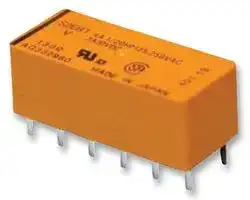


S4EB-12V
Power Relay, 4PST-NO, 12 VDC, 4 A, S Series, Through Hole, Non Latching
- Manufacturer: PANASONIC
- Product type: Power Relays
- Contact Configuration:4PST-NO; Coil Voltage:12VDC; Contact Current:4A; Product Range:S Series; Relay Mounting:Through Hole; Coil Type:Non Latching; Contact Voltage VAC:250V; Relay Terminals
- SVHC: To Be Advised
- Coil Type: Non Latching
- Coil Voltage: 12VDC
- Product Range: S Series
- Relay Mounting: Through Hole
- Coil Resistance: 720ohm
- Contact Current: 4A
- Relay Terminals: Solder
- Contact Material: Silver Alloy
- Contact Voltage VAC: 250V
- Contact Voltage VDC: -
- Approvals & Standards: CSA, UL
- Contact Configuration: 4PST-NO
| Delivery and price | |
|---|---|
| Units per pack | 50 |
| Price | 9.1 € |
| Current stock | 10+ |
| Lead time | 30 days |
Automation Controls Catalog

**RoHS compliant** [|

Protective construction: Sealed type

## **2a2b/3a1b/4a 4A polarized power relays**

**2. Strong resistance to vibration and shock**

Use of 4G-BA technology realizes strong resistance to vibration and shock.

**3. High reliability and long life**

Our application of 4G-BA technology, along with almost perfectly complete twin contact, ensures minimal contact bounce and high reliability.

**4. Ability to provide wide-ranging control**

Use of 4G-BA technology with goldclad silver alloy contacts in a twin contact structure enables control across a broad range from microcurrents of 100 µ A 100 mV DC to 4 A 250 V AC.

## S RELAYS

## **7. Low thermal electromotive force**

High sensitivity (low power consumption) is realized by 4G-BA technology. Separation of the coil and spring sections has resulted in a relay with extremely low levels of thermal electromotive force (approx. 3 µ V).

## **8. DIL terminal array**

Deployed to fit a 2.54 mm .100 inch grid, the terminals are presented in DIL arrays which match the printed circuit board terminal patterns commonly in international use.

**9. Relays that push the boundaries of relay efficiency**

High-density S relays take you close to the limits of relay efficiency.

   **10. Sockets are available.**

**5. Latching types available**

## **FEATURES**

**1. Compact with high sensitivity**

The high-efficiency polarized electromagnetic circuits of the 4-gap balanced armature and our exclusive spring alignment method achieves, with high-sensitivity in a small package, a relay that can be directly controlled by a driver chip.

With 4G-BA technology, as well as single side stable types, convenient 2 coil latching types for circuit memory applications are also available.

**6. Wide variety of contact formations**

## **available**

The compact size of the 4G-BA mechanism enables the provision of many kinds of package, including 2a2b, 3a1b, and 4a. These meet your needs across a broad range of applications.

## **TYPICAL APPLICATIONS**

Telecommunications equipment, data processing equipment, facsimiles, alarm equipment, measuring equipment.

## **4-GAP BALANCED ARMATURE MECHANISM**

## **1. Armature mechanism has excellent resistance to vibration and shock**

The armature structure enables free rotation around the armature center of gravity. Because the mass is maintained in balance at the fulcrum of the axis of rotation, large rotational forces do not occur even if acceleration is applied along any vector. The mechanism has proven to have excellent resistance to vibration and shock. All our S relays are based on this balanced armature mechanism, which is able to further provide many other characteristics.

## **2. High sensitivity and reliability provided by 4-gap balanced armature mechanism**

As a (polarized) balanced armature, the S relay armature itself has two permanent magnets. Presenting four interfaces, the armature has a 4-gap structure. As a result, the rotational axis at either end of the armature is symmetrical and, in an energized into a polarized state, the twin magnetic armature interfaces are subject to repulsion on one side and attraction on the other. This mechanism, exclusive to

Panasonic Corporation, provides a highly efficient polarized magnetic circuit structure that is both highly sensitive and has a small form factor. Moreover, suitability for provision with many types of contact array and other advantages promise to make it possible to provide many of the various characteristics that are coming to be demanded of relays.

2014.02 industrial.panasonic.com/ac/e/

ASCTB207E  201402-T

© Panasonic Corporation 2014

–1–

S

## **HOW IT WORKS** (single side stable type)

1) When current is passed through the coil, the yoke becomes magnetic and polarized.

2) At either pole of the armature, repulsion on one side and attraction on the other side is caused by the interaction of the poles and the permanent magnets of the armature.

3) At this time, opening and closing operates owing to the action of the simultaneously moulded balanced armature mechanism, so that when the force of the contact breaker spring closes the contact on one side, on the other side, the balanced armature opens the contact (2a2b).

**==> picture [128 x 63] intentionally omitted <==**

**----- Start of picture text -----**<br>
Repulsion<br>Permanent magnet<br>Attraction<br>Residual plate<br>Attraction<br>Axis<br>Repulsion<br>N<br>NS<br>NS<br>S<br>**----- End of picture text -----**<br>


## **ORDERING INFORMATION**

**S EB**

Contact arrangement

2: 2 Form A 2 Form B

3: 3 Form A 1 Form B 4: 4 Form A

Operating function Nil: Single side stable L: 1 coil latching* L2: 2 coil latching Nominal coil voltage (DC) 3, 5, 6, 12, 24, 48 V

Notes: 1. *1 coil latching type are manufactured by lot upon receipt of order. 2. Certified by UL and CSA

## **TYPES**

|**TYPES**||||
|---|---|---|---|
|Contact arrangement|Nominal coil voltage|Single side stable<br>Part No.|2 coil latching<br>Part No.|
||3V DC|S2EB-3V|S2EB-L2-3V|
||5V DC|S2EB-5V|S2EB-L2-5V|
|2 Form A 2 Form B|6V DC<br>12V DC|S2EB-6V<br>S2EB-12V|S2EB-L2-6V<br>S2EB-L2-12V|
||24V DC|S2EB-24V|S2EB-L2-24V|
||48V DC|S2EB-48V|S2EB-L2-48V|
||3V DC|S3EB-3V|S3EB-L2-3V|
||5V DC|S3EB-5V|S3EB-L2-5V|
|3 Form A 1 Form B|6V DC<br>12V DC|S3EB-6V<br>S3EB-12V|S3EB-L2-6V<br>S3EB-L2-12V|
||24V DC|S3EB-24V|S3EB-L2-24V|
||48V DC|S3EB-48V|S3EB-L2-48V|
||3V DC|S4EB-3V|S4EB-L2-3V|
||5V DC|S4EB-5V|S4EB-L2-5V|
|4 Form A|6V DC<br>12V DC|S4EB-6V<br>S4EB-12V|S4EB-L2-6V<br>S4EB-L2-12V|
||24V DC|S4EB-24V|S4EB-L2-24V|
||48V DC|S4EB-48V|S4EB-L2-48V|


Standard packing: Carton: 50 pcs.; Case: 500 pcs.

* Sockets available.

## **RATING**

## **1. Coil data**

1) Single side stable

|Type|Nominal coil<br>voltage|Pick-up<br>voltage<br>(at 20°C68°F)|Drop-out<br>voltage<br>(at 20°C68°F)|Nominal operating<br>current [±10%]<br>(at 20°C68°F)|Coil resistance<br>[±10%]<br>(at 20°C68°F)|Nominal operating<br>power|Coil inductance|Max. applied<br>voltage<br>(at 40°C104°F)|
|---|---|---|---|---|---|---|---|---|
||3V DC|||66.7mA|45Ω|200mW|Approx. 23mH|5.5V DC|
||5V DC|70%V or less|10%V or more|38.5mA|130Ω|192mW|Approx. 65mH|9.0V DC|
|Standard|6V DC<br>12V DC|of nominal<br>voltage|of nominal<br>voltage|33.3mA<br>16.7mA|180Ω<br>720Ω|200mW<br>200mW|Approx. 93mH<br>Approx. 370mH|11.0V DC<br>22.0V DC|
||24V DC|(Initial)|(Initial)|8.4mA|2,850Ω|202mW|Approx. 1,427mH|44.0V DC|
||48V DC|||5.6mA|8,500Ω|271mW|Approx. 3,410mH|75.0V DC|


Panasonic Corporation Automation Controls Business Division industrial.panasonic.com/ac/e/

ASCTB207E  201402-T

© Panasonic Corporation 2014

–2–

S

## 2) 2 coil latching

|Type|Nominal coil<br>voltage|Nominal coil<br>voltage|Set voltage<br>(at 20°C68°F)|Reset voltage<br>(at 20°C68°F)|Nominal operating<br>current [±10%]<br>(at 20°C68°F)|Nominal operating<br>current [±10%]<br>(at 20°C68°F)|Nominal operating<br>current [±10%]<br>(at 20°C68°F)|Coil resistance<br>[±10%]<br>(at 20°C68°F)|Coil resistance<br>[±10%]<br>(at 20°C68°F)|Nominal operating<br>power<br>(at 20°C68°F)|Nominal operating<br>power<br>(at 20°C68°F)|Coil inductance|Coil inductance|Max. applied<br>voltage<br>(at 40°C104°F)|
|---|---|---|---|---|---|---|---|---|---|---|---|---|---|---|
||||||Set coil|Reset<br>coil||Set coil|Reset<br>coil|Set coil|Reset<br>coil|Set coil|Reset<br>coil||
|Standard|3V DC||70%V or less<br>of nominal<br>voltage<br>(Initial)|70%V or less<br>of nominal<br>voltage<br>(Initial)|66.7mA|66.7mA||45Ω|45Ω|200mW|200mW|Approx.<br>10mH|Approx.<br>10mH|5.5V DC|
||5V DC||||38.5mA|38.5mA||130Ω|130Ω|192mW|192mW|Approx.<br>31mH|Approx.<br>31mH|9.0V DC|
||6V DC||||33.7mA|33.7mA||180Ω|180Ω|200mW|200mW|Approx.<br>40mH|Approx.<br>40mH|11.0V DC|
||12V DC||||16.7mA|16.7mA||720Ω|720Ω|200mW|200mW|Approx.<br>170mH|Approx.<br>170mH|22.0V DC|
||24V DC||||8.4mA|8.4mA||2,850Ω|2,850Ω|202mW|202mW|Approx.<br>680mH|Approx.<br>680mH|44.0V DC|
||48V DC||||7.4mA|7.4mA||6,500Ω|6,500Ω|355mW|355mW|Approx.<br>1,250mH|Approx.<br>1,250mH|65.0V DC|
|**2. Specif**|**cations**||||||||||||||
|Characte|ristics|Item|||||Specifcations||||||||
|Contact||Arrangement|||||2 Form A 2 Form B, 3 Form A 1 Form B, 4 Form A||||||||
|||Contact resistance (Initial)|||||Max. 50 mΩ(By voltage drop 6 V DC 1A)||||||||
|||Electrostatic capacitance (initial)|||||Approx. 3pF||||||||
|||Contact material|||||Au clad Ag alloy (Cd free)||||||||
|||Thermal electromotive force (at nominal coil voltage)<br>(initial)|||||Approx. 3µV||||||||
|Rating||Nominal switching capacity (resistive load)|||||4 A 250 V AC, 3 A 30 V DC||||||||
|||Max. switching power (resistive load)|||||1,000 VA, 90 W||||||||
|||Max. switching voltage|||||250 V AC, 48 V DC (30 to 48 V DC at less than 0.5 A)||||||||
|||Max. switching current|||||4 A (AC), 3 A (DC)||||||||
|||Minimum operating power|||||100 mW (Single side stable, 2 coil latching) (Except 48V DC type)||||||||
|||Nominal operating power|||||200 mW (Single side stable, 2 coil latching) (Except 48V DC type)||||||||
|||Min. switching capacity (Reference value)*1|||||100µA 100 m V DC||||||||
|Electrical<br>characteris|tics|Insulation resistance (Initial)|||||Min. 10,000MΩ(at 500V DC)<br>Measurement at same location as “Breakdown voltage” section.||||||||
|||Breakdown voltage<br>(Initial)||Between open contacts|||750 Vrms for 1min. (Detection current: 10mA.)||||||||
|||||Between contact sets|||1,000 Vrms for 1min. (Detection current: 10mA.)||||||||
|||||Between contact and coil|||1,500 Vrms for 1min. (Detection current: 10mA.)||||||||
|||Temperature rise (coil) (at 20°C68°F)|||||Max. 35°C<br>(By resistive method, nominal coil voltage applied to the coil; contact carrying current: 4A.)||||||||
|||Operate time [Set time] (at 20°C68°F)|||||Max. 15 ms [15 ms] (Nominal coil voltage applied to the coil, excluding contact bounce time.)||||||||
|||Release time [Reset time] (at 20°C68°F)|||||Max. 10 ms [15 ms] (Nominal coil voltage applied to the coil, excluding contact bounce time.)<br>(without diode)||||||||
|Mechanical<br>characteris|<br>tics|Shock resistance||Functional|||Min. 490 m/s2(Half-wave pulse of sine wave: 11 ms; detection time: 10µs.)||||||||
|||||Destructive|||Min. 980 m/s2(Half-wave pulse of sine wave: 6 ms.)||||||||
|||Vibration resistance||Functional|||10 to 55 Hz at double amplitude of 3 mm (Detection time: 10µs.)||||||||
|||||Destructive|||10 to 55 Hz at double amplitude of 4 mm||||||||
|Expected li|fe|Mechanical|||||Min. 108(at 50 cps)||||||||
|||Electrical|||||Min. 105(4 A 250 V AC), Min. 2×10⁵(3 A 30 V DC) (at 20 times/min.)||||||||
|Conditions||Conditions for operation, transport and storage*2|||||Ambient temperature: –55°C to +65°C–67°F to +149°F<br>Humidity: 5 to 85% R.H. (Not freezing and condensing at low temperature)||||||||
|||Max. operating speed|||||20 times/min. for maximum load, 50 cps for low-level load (1 mA 1 V DC)||||||||
|Unit weight|||||||Approx. 8 g.28 oz||||||||


Notes: *1. This value can change due to the switching frequency, environmental conditions, and desired reliability level, therefore it is recommended to check this with the actual load.

*2. The upper limit of the ambient temperature is the maximum temperature that can satisfy the coil temperature rise value. Refer to Usage, transport and storage conditions in NOTES.

Panasonic Corporation Automation Controls Business Division industrial.panasonic.com/ac/e/

ASCTB207E  201402-T

© Panasonic Corporation 2014

–3–

S

## **REFERENCE DATA**

## 1. Maximum switching power

## 2. Life curve

## 3. Contact reliability

Condition: 1V DC, 1mA Detection level 10 Ω Tasted Sample: S4EB-24V, 10pcs

**==> picture [327 x 137] intentionally omitted <==**

**----- Start of picture text -----**<br>
1,000 99.9<br>99.0<br>95.0<br>500<br>70.0<br>50.0<br>30.0<br>100<br>10.0<br>50 5.0<br>30 2.0 m = 1.6<br>125 V AC 1.0 µ : 79 million time<br>10 (cos250 V AC ϕ  = 1.0) 0.5 σ 95% reliability limit:: 51 million time<br>(cos ϕ  = 1.0) 0.2 14.6 million times<br>(weibul probability paper)<br>0.1<br>0 1 2 3 4 5 1.0 10.0<br>Contact current, A No. of operations,  × 10 [7]<br>410<br>×<br>Life,<br>**----- End of picture text -----**<br>


**==> picture [143 x 136] intentionally omitted <==**

**----- Start of picture text -----**<br>
1,000<br>DC resistive load AC resistive load<br>100<br>10<br>0.1 1 10<br>Contact current, A<br>Contact voltage, V<br>**----- End of picture text -----**<br>


## 4.-(1) Coil temperature rise

## 4.-(2) Coil temperature rise

5. Operate and release time (Single side stable type) Tested Sample: S4EB-24V, 10pcs

Tested Sample: S4EB-24V, 4 Form A

Tested Sample: S4EB-24V, 4 Form A

**==> picture [315 x 134] intentionally omitted <==**

**----- Start of picture text -----**<br>
100 100<br>90 90<br>80 80<br>70 4A 70<br>60 60<br>50 0A 50<br>40 40<br>30 30 Coil operatingpower, 0.2 W<br>20 20<br>10 10<br>0 0<br>0.2 0.4 0.6 0.8 1.0 1.2 1 2 3 4 5 6<br>Coil operating power, W Contact current, A<br>CTemperature rise,  ° CTemperature rise,  °<br>**----- End of picture text -----**<br>


**==> picture [136 x 134] intentionally omitted <==**

**----- Start of picture text -----**<br>
20<br>18<br>16<br>14<br>12 Release time (with diode)<br>10<br>Max.<br>8<br>Min.<br>6 Operate time<br>Max.<br>4 Max. Min.<br>Min.<br>2<br>Release time<br>0<br>80 100 120 140<br>Coil applied voltage, %V<br>Operate/release time, ms<br>**----- End of picture text -----**<br>


## 6. Influence of adjacent mounting

## 7. Thermal electromotive force

**==> picture [528 x 324] intentionally omitted <==**

**----- Start of picture text -----**<br>
Note: When installing an S-relay near another, and there is no effect<br>from an external magnetic field, be sure to leave at least 10 mm  200<br>.394 inch between relays in order to achieve the performance<br>(1) (2) (3) (1) & (3) relays listed in the catalog.<br>are energized<br>NR-H<br>+30 Single side stable +30 2 coil latching 100<br>Drop-out voltage<br>0 0 NF relay S relay<br>Pick-up voltage Pick-up voltage<br>–30 –30<br>5 10 5 10 2 4 6 8 10 12<br>Inter-relay distance, mm Inter-relay distance, mm Minute<br>8. Effect from an external magnetic field<br>Single side stable Single side stable<br>+30 +30<br>φ φ<br>Pick-up voltage Drop-out voltage<br>0 0<br>Pick-up voltage<br>Drop-out voltage<br>–30 –30<br>50 100 50 100<br>+30 2 coil latching G +30 2 coil latching G<br>0 Pick-up voltage 0<br>Pick-up voltage<br>–30 –30<br>50 100 50 100<br>G G<br>V<br>µ<br>Thermal electromotive force,<br>Rate of change, % Rate of change, %<br>Rate of change, % Rate of change, %<br>Rate of change, % Rate of change, %<br>**----- End of picture text -----**<br>


Panasonic Corporation Automation Controls Business Division industrial.panasonic.com/ac/e/

ASCTB207E  201402-T

© Panasonic Corporation 2014

–4–

S

**==> picture [527 x 339] intentionally omitted <==**

**----- Start of picture text -----**<br>
DIMENSIONS  (mm inch) The CAD data of the products with a     GD CAD Data     mark can be downloaded from: http://industrial.panasonic.com/ac/e/<br>CAD Data External dimensions Schematic (Bottom view)<br>28 ± 0.5 12 Single side stable 2 coil latching<br>1.102 ± 0.02 .472 (Deenergized position) (Reset condition)<br>Te 1 este 10 ± 0.5 ce 1 2 3 4 5 6 1 2 3 4 5 6<br>.039 .394 ± 0.02<br>.1574 0.4 0.5.020 2a2b -+ -+ -+<br>1.0 .016<br>1.4 .039 7.62<br>.055 .300 12 11 10 9 8 7 12 11 10 9 8 7<br>Fico 3.118 121 112 103 94 85 76 .3007.62 .47212 fences 1 2 3 4 5 6 1 2 3 4 5 6<br>7anae n<br>.0200.5 5.08.200 3a1b + + +<br>- - -<br>General tolerance:  ± 0.3  ± .012 12 d6d560 11 10 9 8 7 12 6666 11 10 9 8 7<br>PC board pattern (Copper-side view)<br>1 2 3 4 5 6 1 2 3 4 5 6<br>2.54.100 4a + + +<br>- - -<br>12-1.3 dia. 12 11 10 9 8 7 12 11 10 9 8 7<br>.047-.051 dia.<br>HEEajo 2.54 = IH/IB HI<br>.100<br>Tolerance:  ± 0.1  ± .004<br>SAFETY STANDARDS<br>UL/C-UL (Recognized) CSA (Certified)<br>File No. Contact rating File No. Contact rating<br>E43028 4A 250V AC,  [1] /20 HP 125V AC (FLA1.5A) LR26550  4A 250V AC,  [1] /20 HP 125V AC,  [1] /20 HP 250V AC<br>1/20 HP 250V AC (FLA0.75A), 3A 30V DC etc. 3A 30V DC<br>**----- End of picture text -----**<br>


## **NOTES**

**1. For cautions for use, please read “GENERAL APPLICATION GUIDELINES” on page B-1.**

**2. Based on regulations regarding insulation distance, there is a restriction on same-channel load connections between terminals No. 2, 3 and 4, 5, as well as between No. 8, 9 and 10, 11. See the figure below for an example.**

**3. Please note that when this relay (2 Form A 2 Form B type, 3 Form A 1 Form B type) operates and releases, contacts a and b may go ON at the same time.**

**==> picture [168 x 99] intentionally omitted <==**

**----- Start of picture text -----**<br>
2 3 4 5<br>2 3 4 5<br>11 10 9 8<br>11 10 9 8<br>ee<br>• Between 2, 3 and 4, 5:  • Between 2, 3 and 4, 5:<br>different channels, therefore not possible same channels, therefore possible<br>• Between 10, 11 and 8, 9:  • Between 10, 11 and 8, 9:<br>different channels, therefore not possible same channels, therefore possible<br>No good Good<br>**----- End of picture text -----**<br>


Panasonic Corporation Automation Controls Business Division industrial.panasonic.com/ac/e/

ASCTB207E  201402-T

© Panasonic Corporation 2014

–5–

Automation Controls Catalog

**==> picture [95 x 11] intentionally omitted <==**

**----- Start of picture text -----**<br>
ACCESSORIES<br>**----- End of picture text -----**<br>


## S RELAYS PC BOARD SOCKET

## **DIMENSIONS** (mm inch)inch))

**==> picture [491 x 186] intentionally omitted <==**

**----- Start of picture text -----**<br>
(mm inch)inch)) The CAD data of the products with a     CAD Data     mark<br>can be downloaded from: http://industrial.panasonic.com/ac/e/<br>CAD Data External dimensions PC board pattern<br>(Copper-side view)<br>12.4 ± 0.6<br>.488 ± .024 7.6<br>.299<br>5.08 5.08 5.08 5.08 5.08<br>12-1.6 dia. hole .200.200.200.200.200<br>12-.063 dia. hole<br>18.3 ± 0.6<br>.720 ± .024<br>.0471.2 ± .012 ± 0.3 .61015.5 ±± .0240.6 Tolerance:  ± 0.1  ± .004<br>0.4 ± 0.1<br>.016 ± .004<br>4.85 ± 0.3 3.4 ± 0.3<br>.191 ± .012 5.08 ± 0.3 7.62 ± 0.3 .134 ± .012<br>.200 ± .012 .300 ± .012<br>32.4 ± 0.6<br>1.5 ± 0.3 1.276 ± .024 1.5 ± 0.3 Terminal width: 1.3 .051<br>.059 ± .012 .059 ± .012 Terminal thickness: 1.2 .047<br>                                                 General tolerance:  ± 0.3  ± .012<br>Y [a]<br>**----- End of picture text -----**<br>


**RoHS compliant** ~~[~~ **TYPES** Product name Part No. ~~dT~~ S Relays PC board socket S-PS

## **SPECIFICATIONS**

4 A Maximum continuous current Note: Don’t insert or remove relays while in the energized condition. Breakdown voltage 1,500 Vrms between terminals Insulation resistance More than 100 M Ω between terminals at 500 V DC Mega Heat resistance 150 ± 3 ° C (302 ± 5.4 ° F) for 1 hour.

## **NOTES**

## **Inserting and removing method**

Inserting method: Insert the relay as Rib shown in Fig. 1 unit the rib of the relay snaps into the clip of the socket. (Gry [-—¥ Fig. 1 Removing method: (1) Remove the relay straight from the socket holding the shaded portion of the ca Fig. 2 relay as shown in Fig. 2. (2) When sockets are mounted in close proximity, use a slotted screw driver as shown in Fig. 3. oo| Fig. 3

~~OO~~ 2014.02 industrial.panasonic.com/ac/e/ –1– © Panasonic Corporation 2014 ASCTB262E  201402-T
Updated at June 7, 2026
Panasonic Industry is a global leader in the design and manufacture of high-quality electronic components. Renowned for a commitment to continuous innovation, the company provides the essential building blocks that empower modern engineering. From industrial automation to consumer electronics, Panasonic's components are trusted worldwide for their outstanding reliability, efficiency, and long-term performance. The extensive portfolio is anchored by a massive selection of passive components, featuring an industry-leading range of aluminium electrolytic, film, and polymer capacitors. Alongside these advanced capacitance solutions, engineers rely on Panasonic's robust power inductors and a highly versatile array of electromechanical devices, including solid-state, power, and signal relays engineered to excel in demanding environments. Beyond core passives and switching solutions, the offering encompasses critical circuit protection devices such as TVS varistors and NTC thermistors, as well as sophisticated thermal management materials. Panasonic also delivers precision light and motion sensors, highly reliable batteries, and advanced Bluetooth and WLAN connectivity modules, providing a comprehensive ecosystem of components to support next-generation technological design.
About Novapart
Novapart is a B2B electronic component broker specialising in stock shortages and cost reduction. We source hard-to-find parts and identify compliant alternatives across a catalogue of 540,000+ components from 500+ manufacturers.
Learn more →Stock Shortage Specialist
When a component is unavailable, discontinued or has an unacceptable lead time, we tap into our network of vetted European and Asian distributors to source what you need — without compromising on quality or traceability.
Request a quote →Compliant Alternatives
We identify pin-to-pin, electrically equivalent substitutes that meet the same certifications (RoHS, AEC-Q100, REACH) as your original specification — validated against datasheets, not just part numbers. Often at a lower cost.
BOM Analysis service →