
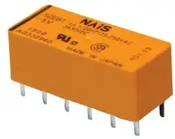


S2EB-L2-5V.
PCB Relay
- Manufacturer: PANASONIC
- Product type: Power Relays
- Contacts:DPST; Coil Voltage D
- Coil Type: Latching Dual Coil
- Coil Voltage: 5VDC
- Product Range: S Series
- Relay Terminals: Solder
- Contact Material: Silver Alloy
- Contact Voltage VAC: 250V
- Contact Voltage VDC: 30V
- Contact Configuration: DPST
| Delivery and price | |
|---|---|
| Units per pack | 500 |
| Price | 31.0 € |
| Current stock | 50+ |
| Lead time | 30 days |
S

## **4 A CAPACITY, THE VARIETY OF CONTACT ARRANGEMENTS**

## S RELAYS

## **FEATURES**

**==> picture [117 x 45] intentionally omitted <==**

**----- Start of picture text -----**<br>
12.0<br>28.0 .472<br>1.102<br>10.4<br>.409<br><ggoS<br>**----- End of picture text -----**<br>


mm inch

- **The variety of contact arrangements 2 Form A 2 Form B, 3 Form A 1 Form B, 4 Form A**

- **Latching types available**

- **High sensitivity in small size 100 mW pick-up and 200 mW nominal operating power**

- **High shock and vibration resistance Shock: 50 G Vibration: 10 to 55 Hz at double amplitude of 3 mm .118 inch**

- **Wide switching range From 100** µ **A 100 mV DC to 4 A 250 V AC**

- **Low thermal electromotive force Approx. 3** µ **V**

- **Dual-In-Line packaging arrangement**

- **Amber types available**

## **SPECIFICATIONS**

## **Contacts**

## **Characteristics (at 25** ° **C 77** ° **F 50% Relative humidity)**

|2 Form A 2 Form B,|||20 cpm for maximum load,|
|---|---|---|---|
|Arrangement<br>3 Form A 1 Form B,|Max. operating speed||50 cps for low-level load|
|4 Form A|||(1 mA 1 V DC)|
|Initial contact resistance, max.<br>(By voltage drop 6 V DC 1 A)<br>50 mΩ<br>Initial contact pressure<br>Approx. 12 g.42 oz<br>Contact material<br>Gold clad silver alloy<br>Electrostatic capacitance<br>Approx. 3pF|Initial insulation resistance*1<br>Initial<br>breakdown<br>voltage*2<br>Between open contacts<br>Between contact sets<br>Between contacts and<br>coil<br>|<br>Cid<br>|<br>C—C—izdC<br>|||10,000 MΩat 500 V DC<br>750 Vrms<br>1,000 Vrms<br>1,500 Vrms|
|Thermal electromotive force<br>(at nominal coil voltage)<br>Approx. 3µV|Operate time*3<br>(at nominal voltage)(at 20°C)||Max. 15 ms (Approx. 8 ms)|
|**Coil (polarized) (at 20**°**C68**°**F)**<br>**Notes:**<br>#1 This value can change due to the switching frequency, environmental conditions,<br>and desired reliability level, therefore it is recommended to check this with the<br>actual load.<br>**Remarks**<br>*Specifications will vary with foreign standards certification ratings.<br>Rating<br>(resistive)<br>Nominal switching capacity<br>4 A 250 V AC, 3 A 30 V DC<br>Maximum switching power<br>1,000 VA, 90 W<br>Maximum switching voltage<br>250 V AC, 30 V DC<br>(48 VDC at less than 0.5 A)<br>Max. switching current<br>4 A (AC), 3 A (DC)<br>Min. switching capacity#1<br>100µA 100 m V DC<br>Expected<br>life (min.<br>operations)<br>Mechanical (at 50 cps)<br>108<br>Electrical<br>(at 20 cpm)<br>4 A 250 V AC<br>105<br>3 A 30 V DC<br>2×10⁵<br>Single side<br>stable<br>Minimum operating power<br>Approx. 100 mW<br>Nominal operating power<br>Approx. 200 mW<br>Latching<br>Minimum set and reset<br>Approx. 100 mW<br>Nominal set and reset<br>Approx. 200 mW<br>|Po<br>|<br>Po<br>Po<br>Po<br>i<br>|<br>—————|Release time (without diode)*3<br>(at nominal voltage)(at 20°C)<br>Set time*3(latching)<br>(at nominal voltage)(at 20°C)<br>Reset time*3(latching)<br>(at nominal voltage)(at 20°C)<br>Initial contact bounce, max.<br>Temperature rise<br>(at nominal voltage)(at 20°C)<br>Shock resistance<br>Functional*4<br>Destructive*5<br>Vibration resistance<br>Functional*6<br>Destructive<br>Conditions for operation,<br>transport and storage*7<br>(Not freezing and condens-<br>ing at low temperature)<br>Ambient<br>temp.<br>Humidity<br>Unit weight<br>||sd<br>ae<br>| ||||Max. 10 ms (Approx. 5 ms)<br>Max. 15 ms (Approx. 8 ms)<br>Max. 15 ms (Approx. 8 ms)<br>1 ms<br>Max. 35°C with nominal coil<br>voltage and at maximum<br>switching current<br>Min. 490 m/s2{50 G}<br>Min. 980 m/s2{100 G}<br>176.4 m/s2{18 G}, 10 to 55 Hz<br>at double amplitude of 3 mm<br>235.2 m/s2{24 G}, 10 to 55 Hz<br>at double amplitude of 4 mm<br>–40°C to +65°C<br>–40°F to +149°F<br>5 to 85% R.H.<br>Approx. 8 g.28 oz|


- Specifications will vary with foreign standards certification ratings.

- [1] Measurement at same location as “Initial breakdown voltage” section

- [2] Detection current: 10mA

- [3] Excluding contact bounce time

- [4] Half-wave pulse of sine wave: 11ms; detection time: 10µs

- [5] Half-wave pulse of sine wave: 6ms

- [6] Detection time: 10µs

- [7] Refer to 6. Conditions for operation, transport and storage mentioned in AMBIENT ENVIRONMENT

## **TYPICAL APPLICATIONS**

Telecommunications equipment, data processing equipment, facsimiles, alarm equipment, measuring equipment.

All Rights Reserved © C OPYRIGHT Matsushita Electric Works, Ltd.

S

## **ORDERING INFORMATION**

**==> picture [488 x 76] intentionally omitted <==**

**----- Start of picture text -----**<br>
Ex. S 2 EB L2 48V<br>Contact arrangement Classification of type Operating function Coil voltage (DC)<br>2: 2 Form A 2 Form B EB: Amber sealed type Nil: Single side stable 3, 5, 6, 12, 24, 48 V<br>3: 3 Form A 1 Form B L2: 2 coil latching<br>4: 4 Form A<br>**----- End of picture text -----**<br>


- (Notes) 1. Standard packing  Carton: 50 pcs. Case: 500 pcs.

2. 1 coil latching also available as option. Contact our sales office for details.

3. UL/CSA approved type is standard.

4. 1 coil latching type available.

## **TYPES AND COIL DATA  at 20** ° **C 68** ° **F**

## **Single side stable**

|Type|Nominal<br>voltage,<br>V DC|Pick-up<br>voltage,<br>V DC (max.)|Pick-up<br>voltage,<br>V DC (max.)|Drop-out<br>voltage,<br>V DC (min.)|Drop-out<br>voltage,<br>V DC (min.)|Nominal<br>operating<br>current,<br>mA|Coil resistance,<br>Ω<br>(<br>±<br>10%)|Coil resistance,<br>Ω<br>(<br>±<br>10%)|Inductance,<br>mH|Inductance,<br>mH|Nominal<br>operating<br>power,<br>mW|Maximum<br>allowable<br>voltage,<br>V DC (40<br>°<br>C)|
|---|---|---|---|---|---|---|---|---|---|---|---|---|
|S<br>❑<br>EB-3V|3|2.1||0.3||66.7|45||23||200|5.5|
|S<br>❑<br>EB-5V|5|3.5||0.5||38.5|130||65||192|9.0|
|S<br>❑<br>EB-6V|6|4.2||0.6||33.3|180||93||200|11.0|
|S<br>❑<br>EB-12V|12|8.4||1.2||16.7|720||370||200|22.0|
|S<br>❑<br>EB-24V|24|16.8||2.4||8.4|2,850||1,427||202|44.0|
|S<br>❑<br>EB-48V|48|33.6||4.8||5.6|8,500||3,410||271|75.0|
|**2 coil latchin**|**g**||||||||||||
|Type|Nominal voltage,<br>V DC||Set and reset<br>voltage,<br>V DC (max.)||Nominal operating<br>current,<br>mA||Coil resistance,<br>Ω<br>(<br>±<br>10%)||Inductance,<br>mH||Nominal<br>operating<br>power,<br>mW|Maximum<br>allowable<br>voltage,<br>V DC (40<br>°<br>C)|
||||||||Coil I|Coil II|Coil I|Coil II|||
|S<br>❑<br>EB-L2-3V|3||2.1||66.7||45|45|10|10|200|5.5|
|S<br>❑<br>EB-L2-5V|5||3.5||38.5||130|130|31|31|192|9.0|
|S<br>❑<br>EB-L2-6V|6||4.2||33.7||180|180|40|40|200|11.0|
|S<br>❑<br>EB-L2-12V|12||8.4||16.7||720|720|170|170|200|22.0|
|S<br>❑<br>EB-L2-24V|24||16.8||8.4||2,850|2,850|680|680|202|44.0|
|S<br>❑<br>EB-L2-48V|48||33.6||7.4||6,500|6,500|1,250|1,250|355|65.0|


Note: Insert 2, 3 or 4 in ❑ for contact form required.

**==> picture [529 x 296] intentionally omitted <==**

**----- Start of picture text -----**<br>
DIMENSIONS mm inch<br>1.10228±±0.50.02 .47212 PC board pattern (Copper-side view)<br>1 10±0.5<br>.039 .394±0.02<br>4 0.5 2.54<br>.157 0.4 .020 .100<br>1.0 .016<br>1.4 .039 7.62<br>.055 .300<br>12-1.3 DIA.<br>.1183 121 112 103 49 58 67 7.62.300 .47212 .047-.051 DIA. .1002.54<br>.0200.5 .2005.08<br>General tolerance: ±0.3 ±.012 Tolerance: ±0.1 ±.003<br>Schematic  (Bottom view)<br>Single side stable 2a2b 1 2 3 4 5 6 3a1b 1 2 3 4 5 6 4a 1 2 3 4 5 6<br>Deenergized position + + +<br>- - -<br>12 11 10 9 8 7 12 11 10 9 8 7 12 11 10 9 8 7<br>2 coil latching 2a2b 1 2 3 4 5 6 3a1b 1 2 3 4 5 6 4a 1 2 3 4 5 6<br>Diagram shows the “reset”  + + + + + +<br>Set Reset Set Reset Set Reset<br>position when terminals 6  - - - - - -<br>and 7 are energized.<br>Energize terminals 1 and  12 11 10 9 8 7 12 11 10 9 8 7 12 11 10 9 8 7<br>12 to transfer contacts.<br>**----- End of picture text -----**<br>


All Rights Reserved © C OPYRIGHT Matsushita Electric Works, Ltd.

S

## **REFERENCE DATA**

## 1. Maximum switching power

## 2. Life curve

## 3. Contact reliability

Condition: 1V DC, 1mA Detection level 10 Ω Tasted Sample: S4EB-24V, 10pcs

**==> picture [528 x 315] intentionally omitted <==**

**----- Start of picture text -----**<br>
1,000 1,000 99.9<br>DC resistive load AC resistive load 99.095.0<br>500<br>70.0<br>50.0<br>100 30.0<br>100<br>10.0<br>50 5.0<br>10 30 2.0 m = 1.6<br>125 V AC 1.0 µ: 79 million time<br>10 250 V AC(cosϕ = 1.0) 0.5 σ95% reliability limit:: 51 million time<br>(cosϕ = 1.0) 0.2 14.6 million times(weibul probability paper)<br>0.1<br>0.1 1 10 0 1 2 3 4 5 1.0 10.0<br>Contact current, A Contact current, A No. of operations, ×10 [7]<br>4.-(1) Coil temperature rise 4.-(2) Coil temperature rise 5. Operate and release time<br>Tested Sample: S4EB-24V, 4 Form A Tested Sample: S4EB-24V, 4 Form A (Single side stable type)<br>Tested Sample: S4EB-24V, 10pcs<br>100 100 20<br>90 90 18<br>80 80 16<br>70 4A 70 14<br>60 60 12 Release time (with diode)<br>50 0A 50 10<br>Max.<br>40 40 8<br>Min.<br>30 30 Coil operatingpower, 0.2 W 6 Operate time<br>Max.<br>20 20 4 Max. Min.<br>Min.<br>10 10 2<br>Release time<br>0 0 0<br>0.2 0.4 0.6 0.8 1.0 1.2 1 2 3 4 5 6 80 100 120 140<br>Coil operating power, W Contact current, A Coil applied voltage, %V<br>410<br>×<br>Life,<br>Contact voltage, V<br>CTemperature rise, ° CTemperature rise, °<br>Operate/release time, ms<br>**----- End of picture text -----**<br>


## 6. Influence of adjacent mounting

**==> picture [291 x 121] intentionally omitted <==**

**----- Start of picture text -----**<br>
(1) & (3) relays<br>(1) (2) (3)<br>are energized<br>Single side stable 2 coil latching<br>+30 +30<br>Drop-out voltage<br>0 0<br>Pick-up voltage<br>–30 –30<br>5 10 5 10<br>Rate of change, % Rate of change, %<br>**----- End of picture text -----**<br>


S

**ACCESSORIES**

**==> picture [528 x 230] intentionally omitted <==**

**----- Start of picture text -----**<br>
Specifications<br>Breakdown voltage 1,500 Vrms between terminals<br>Insulation resistance More than 100 MΩ between terminals at 500 V DC Mega<br>Heat resistance 150 ±3°C (302 ±5.4°F) for 1 hour.<br>S Relay Socket,  Maximum continuous current 4 A<br>————— S-PS (Note: Don't insert or remove relays while in the energized condition.)<br>Dimensions mm inch<br>PC board pattern (Copper-side view)<br>12.4±0.6<br>.488±.024<br>7.6<br>.299<br>18.3±0.6 5.08 5.08 5.08 5.08 5.08<br>.720±.024 12-1.6 DIA. HOLE .200.200.200.200.200<br>.0471.2±.012±0.3 .61015.5±±.0240.6 12-.063 DIA. HOLE<br>0.4±0.1<br>.016±.004<br>4.85±0.3 3.4±0.3<br>.191±.012 5.08±0.3 7.62±0.3 .134±.012<br>.200±.012 .300±.012<br>‘ hem 32.4±0.6 a<br>1.5±0.3 1.276±.024 1.5±0.3 Terminal width: 1.3 .051<br>.059±.012 .059±.012 Terminal thickness: 1.2 .047<br>**----- End of picture text -----**<br>


## **Inserting and removing method**

Inserting method: Insert the relay as Rib shown in Fig. 1 unit the rib of the relay snaps into the clip of the socket. =i Fig. 1

Removing method:

(1) Remove the relay straight from the socket holding the shaded portion of the [ay Fig. 2 relay as shown in Fig. 2. (2) When sockets are mounted in close proximity, use a slotted screw driver as shown in Fig. 3.

**==> picture [14 x 6] intentionally omitted <==**

**----- Start of picture text -----**<br>
Fig. 3<br>**----- End of picture text -----**<br>


## **NOTES**

1. Special use of 2 coil latching types: 2 Reset position of 2a2b type 2. Soldering operations should be ways can be considered if 2 coil latching accomplished as quick as possible; types are used as 1 coil latching types. within 10 seconds at 250°C 482°F solder (A) Reverse polarity is applied to the set temperature or 3 seconds at 350°C coil of 2 coil latching type. - 1 2 3 4 5 6 + 662°F. The header portion being sealed (B) By shorting terminals 12 and 7, apply with epoxy resin, undue subjection to plus to 1, minus to 6 at set and plus to 6, heat may cause loss of seal. Solder minus to 1 at reset. Applied coil voltage 12 11 10 9 8 7 should not be permitted to remain on the should be the same as the nominal. header. Operating power will be reduced to onehalf.

## **CAUTIONS FOR USE**

**==> picture [526 x 88] intentionally omitted <==**

**----- Start of picture text -----**<br>
Based on regulations regarding insulation distance, there is a  2 3 4 5<br>restriction on same-channel load connections between terminals<br>No. 2, 3 and 4, 5, as well as between No. 8, 9 and 10, 11. See  11 10 9 8 2 3 4 5<br>the figure below for an example. 11 10 9 8<br>• Between 2, 3 and 4, 5: different channels, therefore not possible • Between 2, 3 and 4, 5: same channels, therefore possible<br>• Between 10, 11 and 8, 9: different channels, therefore not possible • Between 10, 11 and 8, 9: same channels, therefore possible<br>No good Good<br>**----- End of picture text -----**<br>


## **For Cautions for Use, see Relay Technical Information**

All Rights Reserved © C OPYRIGHT Matsushita Electric Works, Ltd.
Updated at June 10, 2026
Panasonic Industry is a global leader in the design and manufacture of high-quality electronic components. Renowned for a commitment to continuous innovation, the company provides the essential building blocks that empower modern engineering. From industrial automation to consumer electronics, Panasonic's components are trusted worldwide for their outstanding reliability, efficiency, and long-term performance. The extensive portfolio is anchored by a massive selection of passive components, featuring an industry-leading range of aluminium electrolytic, film, and polymer capacitors. Alongside these advanced capacitance solutions, engineers rely on Panasonic's robust power inductors and a highly versatile array of electromechanical devices, including solid-state, power, and signal relays engineered to excel in demanding environments. Beyond core passives and switching solutions, the offering encompasses critical circuit protection devices such as TVS varistors and NTC thermistors, as well as sophisticated thermal management materials. Panasonic also delivers precision light and motion sensors, highly reliable batteries, and advanced Bluetooth and WLAN connectivity modules, providing a comprehensive ecosystem of components to support next-generation technological design.
About Novapart
Novapart is a B2B electronic component broker specialising in stock shortages and cost reduction. We source hard-to-find parts and identify compliant alternatives across a catalogue of 540,000+ components from 500+ manufacturers.
Learn more →Stock Shortage Specialist
When a component is unavailable, discontinued or has an unacceptable lead time, we tap into our network of vetted European and Asian distributors to source what you need — without compromising on quality or traceability.
Request a quote →Compliant Alternatives
We identify pin-to-pin, electrically equivalent substitutes that meet the same certifications (RoHS, AEC-Q100, REACH) as your original specification — validated against datasheets, not just part numbers. Often at a lower cost.
BOM Analysis service →