


S15LPRGB7Q
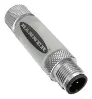
Indicator, Flashing, Blue, Green, Red, 30 VDC, IP65/IP67/IP68, -40 to 45 °C, 57.8mm H, 15mm Lens
- Manufacturer: BANNER ENGINEERING
- Product type: Visual Signal Indicator Units
- SVHC: No SVHC (27-Jun-2024)
- Power Rating: -
- Lens Diameter: 15mm
- Product Range: S15L Pro Series
- External Height: 57.8mm
- IP / NEMA Rating: IP65, IP67, IP68
- Module Lens Colour: Blue, Green, Red
- Supply Voltage VAC: -
- Supply Voltage VDC: 30V
- Visual Signal Type: Flashing
- Operating Temperature Max: 45°C
- Operating Temperature Min: -40°C
| Delivery and price | |
|---|---|
| Units per pack | 10 |
| Price | 72.58 € |
| Current stock | 10+ |
| Lead time | 30 days |
## S15L Pro In-Line RGB Indicator Instruction Manual

**==> picture [464 x 368] intentionally omitted <==**

Original Instructions p/n: 242116 Rev. A April 18, 2024 © Banner Engineering Corp. All rights reserved.

## Contents

## **Chapter 1 Features**

Models ........................................................................................................................................................................................................... 3

**Chapter 2 Configuration Instructions**

Pro Editor....................................................................................................................................................................................................... 4 Wiring............................................................................................................................................................................................................. 4 Pro Editor Configuration for the S15L............................................................................................................................................................ 4

**Chapter 3 Specifications** FCC Part 15 Class B for Unintentional Radiators.......................................................................................................................................... 8 Industry Canada ICES-003(B)....................................................................................................................................................................... 8 Dimensions.................................................................................................................................................................................................... 9 **Chapter 4 Accessories** Cordsets ...................................................................................................................................................................................................... 10 Brackets........................................................................................................................................................................................................11 Quick-Disconnect Cap..................................................................................................................................................................................11 Pro Editor Hardware.....................................................................................................................................................................................11

**Chapter 5 Banner Engineering Corp Limited Warranty..................................................... 13**

S15L Pro In-Line RGB Indicator Instruction Manual

## Chapter Contents

Models.................................................................................................................................................................................................................. 3

## Chapter 1 Features

## 15 mm Multicolor RGB Indicator

**==> picture [87 x 35] intentionally omitted <==**

- Bright, programmable indicator light with RGB LEDs

- • Rugged overmolded indicator segment design meets IP65, IP67 and IP68 • Connect directly to a compatible sensor or anywhere in-line for easy visual indication

- • Programmable color, flashing, and intensity settings

## Models

Model Housing Style Control Connector Integral 5-pin M12 male/female quickS15LPRGB7Q S15 Pro Discrete disconnect connector

April 18, 2024

page 3

© Banner Engineering Corp. All rights reserved.

S15L Pro In-Line RGB Indicator Instruction Manual

## Chapter Contents

Pro Editor ............................................................................................................................................................................................................. 4 Wiring ................................................................................................................................................................................................................... 4 Pro Editor Configuration for the S15L .................................................................................................................................................................. 4 Chapter 2 Configuration Instructions

## Pro Editor

**==> picture [112 x 67] intentionally omitted <==**

Use Banner's Pro Editor software and Pro Converter Cable to create custom configurations by selecting different colors, flash patterns, and animations. For more information visit www.bannerengineering.com/proeditor.

## Wiring

**==> picture [500 x 92] intentionally omitted <==**

**----- Start of picture text -----**<br>
5-pin M12 Male 5-pin M12 Female Pin Wire Color Description<br>1 Brown Input 2: 12 V DC to 30 V DC<br>1 2 2 White Input 3: 12 V DC to 30 V DC<br>2 1<br>4 3 3 Blue DC Common<br>3 5 4 5 4 Black Input 1: 12 V DC to 30 V DC<br>5 Gray Input 4 (Default Flashing Input): 12 V DC to 30 V DC<br>**----- End of picture text -----**<br>


## Default Color Definition

**==> picture [500 x 62] intentionally omitted <==**

**----- Start of picture text -----**<br>
Red Yellow Green Cyan Blue Magenta White<br>Input 1 X X X X<br>Input 2 X X X X<br>Input 3 X X X X<br>**----- End of picture text -----**<br>


An "X" denotes an active input, for example when Input 1 and Input 3 are active, the indicator will show Magenta.

## Pro Editor Configuration for the S15L

Banner's Pro Editor software offers an easy way to configure Pro Series-enabled touch and indicator devices, allowing users full control of device states. The easy-to-use configuration software provides a variety of tools and capabilities to solve a wide range of applications. Configure any Pro Series-enabled device using the free Pro Editor software, available for download at www.bannerengineering.com/proeditor.

Color 1 and Color 2 Options

**==> picture [500 x 62] intentionally omitted <==**

**----- Start of picture text -----**<br>
Green Yellow Sky Blue Rose<br>Red Lime Green Blue White<br>Orange Spring Green Violet Custom 1<br>Amber Cyan Magenta Custom 2<br>**----- End of picture text -----**<br>


April 18, 2024

page 4

© Banner Engineering Corp. All rights reserved.

Configuration Instructions

S15L Pro In-Line RGB Indicator Instruction Manual

## Intensity 1 or Intensity 2 Options

**==> picture [500 x 91] intentionally omitted <==**

**----- Start of picture text -----**<br>
Intensity Description<br>High 100%<br>Medium 60%<br>Low 25%<br>Off 0%<br>Custom Set a custom intensity percentage<br>**----- End of picture text -----**<br>


## Animation Settings

**==> picture [500 x 217] intentionally omitted <==**

**----- Start of picture text -----**<br>
Animation Description<br>Off Device OFF, no animation displays<br>Steady Color 1 is solid ON at the defined intensity<br>Flash Color 1 flashes at the defined speed, color intensity, and pattern (normal, strobe, three pulse, SOS, or random)<br>Two Color Flash Color 1 and Color 2 flash alternately at the defined speed, color intensities, and pattern (normal, strobe, three pulse, SOS, or<br>random)<br>50/50 Color 1 is displayed on one side of the indicator and Color 2 is displayed on the other side of the indicator at the defined color<br>intensities<br>50/50 Rotate Color 1 is displayed on one side of the indicator and Color 2 is displayed on the other side of the indicator while alternating sides at<br>the defined speed and color intensities<br>Intensity Sweep Color 1 continuously increases and decreases intensity between 0% to 100% at defined speed and color intensity<br>Color 1 and Color 2 define the end values of a line across the color gamut. The light continuously displays a color by moving along<br>Color Sweep<br>the line at the defined speed and color intensity<br>Wave Color 1 increases and decreases intensity between 0% to 100% at defined speed and color intensity on one side of the indicator,<br>then switches to other side of indicator; then Color 2 repeats same sequence<br>Double Wave Color 1 increases intensity between 0% to 100% at defined speed and color intensity holding on one side of the indicator, then the<br>other side of indicator increases intensity between 0% to 100%; then Color 2 repeats same sequence<br>**----- End of picture text -----**<br>


## Pulse Patterns

**==> picture [500 x 100] intentionally omitted <==**

**----- Start of picture text -----**<br>
Pattern Description<br>Normal Alternating Color 1; Off or Color 2 at 50% duty cycle<br>Strobe Continuous Color 1; Off or Color 2 flashes at 20% duty cycle<br>3-Pulse Three consecutive Color 1 pulses at 10% duty cycle on Off or Color 2 background<br>SOS Short pulse, short pulse, short pulse, long pulse, long pulse, long pulse, short pulse, short pulse, short pulse<br>alternating Color 1 and Off or Color 2<br>Random Random sequence of Color 1 and Off or Color 2 flashes<br>**----- End of picture text -----**<br>


## Speed

**==> picture [500 x 77] intentionally omitted <==**

**----- Start of picture text -----**<br>
Speed Description<br>Slow 0.5 Hz<br>Medium 1 Hz<br>Fast 5 Hz<br>Custom Flash Rate Set a custom flash rate in Hz<br>**----- End of picture text -----**<br>


The three I/O states available in Pro Editor are:

April 18, 2024

page 5

© Banner Engineering Corp. All rights reserved.

S15L Pro In-Line RGB Indicator Instruction Manual

Configuration Instructions

**==> picture [500 x 123] intentionally omitted <==**

**----- Start of picture text -----**<br>
I/O State Configuration Settings Description<br>Configurations made in this state assign one wire to one state, with the following override control:<br>• Pin 1 (Brown) overrides Pin 4 (Black)<br>Basic • Pin 2 (White) overrides Pins 1 and 4 (Brown and Black)<br>• Pin 5 (Gray) overrides Pins 1, 2, and 4 (Brown, White, and Black)<br>Advanced I/O state with full fifteen state options for maximum configuration. Configurations made in Advanced assign<br>binary wiring combinations of all valid inputs to each state.<br>Three state control for use with I/O block. Configurations made in I/O Block assign states to the black,<br>I/O Block white, and combination of black and white wires for use with I/O blocks for which power (brown) and<br>common (blue) are always on for five pin connections.<br>**----- End of picture text -----**<br>


page 6

April 18, 2024

© Banner Engineering Corp. All rights reserved.

S15L Pro In-Line RGB Indicator Instruction Manual

## Chapter Contents

FCC Part 15 Class B for Unintentional Radiators ................................................................................................................................................ 8 Industry Canada ICES-003(B).............................................................................................................................................................................. 8 Dimensions........................................................................................................................................................................................................... 9

## Chapter 3

## Specifications

## Supply Voltage

12 V DC to 30 V DC

Supply Current 6 0 mA maximum current at 12 V DC 35 mA typical at 24 V DC

Supply Protection Circuitry

Protected against reverse polarity and transient voltages

Leakage Current Immunity

400 μA

Input Response Time

250 milliseconds maximum

Flash

Default 1 Hz flash rate through flash input wire

Operating Conditions

## Connections

Integral 5-pin M12 male/female quick-disconnect connector Models with a quick disconnect require a mating cordset

Required Overcurrent Protection

WARNING: Electrical connections must be made by qualified personnel in accordance with local and national electrical codes and regulations.

Overcurrent protection is required to be provided by end product application per the supplied table.

Overcurrent protection may be provided with external fusing or via Current Limiting, Class 2 Power Supply. Supply wiring leads < 24 AWG shall not be spliced. For additional product support, go to www.bannerengineering.com.

–40 °C to +45 °C (–40 °F to +113 °F)

Humidity: 90% at +50 °C maximum relative humidity (noncondensing) Storage Temperature: –40 °C to +70 °C (–40 °F to +158 °F)

Environmental Rating

IP65, IP67, IP68, UL Type 1

Construction Coupling Material: Nickel-plated brass Connector Body: PVC diffuse white

## Vibration and Mechanical Shock

Meets IEC 60068-2-6 requirements (Vibration: 10 Hz to 55 Hz, 0.5 mm amplitude, 5 minutes sweep, 30 minutes dwell) Meets IEC 60068-2-27 requirements (Shock: 15G 11 ms duration, half sine wave)

**==> picture [208 x 68] intentionally omitted <==**

**----- Start of picture text -----**<br>
Supply  Supply<br>Required Overcurrent  Required Overcurrent<br>Wiring  Wiring<br>Protection (A) Protection (A)<br>(AWG) (AWG)<br>20 5.0 26 1.0<br>22 3.0 28 0.8<br>24 1.0 30 0.5<br>**----- End of picture text -----**<br>


## Certifications

Banner Engineering BV Park Lane, Culliganlaan 2F bus 3 1831 Diegem, BELGIUM Turck Banner LTD Blenheim House Blenheim Court Wickford, Essex SS11 8YT GREAT BRITAIN

April 18, 2024

page 7

© Banner Engineering Corp. All rights reserved.

S15L Pro In-Line RGB Indicator Instruction Manual

Specifications

## Default Indicator Characteristics

**==> picture [483 x 264] intentionally omitted <==**

**----- Start of picture text -----**<br>
Color Coordinates [(1)]<br>Dominant Wavelength (nm) or Color  Lumen Output (Typical at 25<br>Color<br>Temperature (CCT) x y °C)<br>White 7000K 0.31 0.295 1.16<br>Green 527 0.175 0.7 1.8<br>Red 620 0.69 0.307 1.3<br>Orange 604 0.628 0.356 1.35<br>Amber 597 0.593 0.383 1.35<br>Yellow 588 0.537 0.426 1.35<br>Lime Green 577 0.466 0.481 1.8<br>Spring Green 513 0.178 0.562 1.6<br>Cyan 498 0.195 0.396 1.3<br>Sky Blue 489 0.17 0.303 1.1<br>Blue 465 0.144 0.055 0.25<br>Violet - 0.337 0.144 0.7<br>Magenta - 0.506 0.251 1<br>Rose - 0.593 0.282 1.1<br>**----- End of picture text -----**<br>


## FCC Part 15 Class B for Unintentional Radiators

(Part 15.105(b)) This equipment has been tested and found to comply with the limits for a Class B digital device, pursuant to part 15 of the FCC Rules. These limits are designed to provide reasonable protection against harmful interference in a residential installation. This equipment generates, uses, and can radiate radio frequency energy and, if not installed and used in accordance with the instructions, may cause harmful interference to radio communications. However, there is no guarantee that interference will not occur in a particular installation. If this equipment does cause harmful interference to radio or television reception, which can be determined by turning the equipment off and on, the user is encouraged to try to correct the interference by one or more of the following measures:

- Reorient or relocate the receiving antenna.

- Increase the separation between the equipment and receiver.

- Connect the equipment into an outlet on a circuit different from that to which the receiver is connected.

- Consult the dealer or an experienced radio/TV technician for help.

(Part 15.21) Any changes or modifications not expressly approved by the party responsible for compliance could void the user’s authority to operate this equipment.

## Industry Canada ICES-003(B)

This device complies with CAN ICES-3 (B)/NMB-3(B). Operation is subject to the following two conditions: 1) This device may not cause harmful interference; and 2) This device must accept any interference received, including interference that may cause undesired operation.

Cet appareil est conforme à la norme NMB-3(B). Le fonctionnement est soumis aux deux conditions suivantes : (1) ce dispositif ne peut pas occasionner d'interférences, et (2) il doit tolérer toute interférence, y compris celles susceptibles de provoquer un fonctionnement non souhaité du dispositif.

> (1) Refer to the CIE 1931 (x,y) Chromaticity Diagram to show equivalent color with indicated color coordinates. Actual coordinates may differ ± 5%.

page 8

April 18, 2024

© Banner Engineering Corp. All rights reserved.

Specifications

S15L Pro In-Line RGB Indicator Instruction Manual

## Dimensions

All measurements are listed in millimeters [inches], unless noted otherwise.

**==> picture [228 x 111] intentionally omitted <==**

**----- Start of picture text -----**<br>
57.8<br>[2.27]<br>27.9<br>[1.1]<br>15.0<br>[0.59]<br>M12 X 1  - 6g<br>**----- End of picture text -----**<br>


**==> picture [38 x 6] intentionally omitted <==**

**----- Start of picture text -----**<br>
M12 X 1  - 6H<br>**----- End of picture text -----**<br>


April 18, 2024

page 9

© Banner Engineering Corp. All rights reserved.

S15L Pro In-Line RGB Indicator Instruction Manual

## Chapter Contents

Cordsets ............................................................................................................................................................................................................. 10 Brackets ..............................................................................................................................................................................................................11 Quick-Disconnect Cap.........................................................................................................................................................................................11 Pro Editor Hardware............................................................................................................................................................................................11

## Chapter 4 Accessories

## Cordsets

**==> picture [500 x 456] intentionally omitted <==**

**----- Start of picture text -----**<br>
5-Pin Threaded M12 Cordsets—Single Ended<br>Model  Length  Style  Dimensions  Pinout (Female)<br>MQDC1-501.5 0.5 m (1.5 ft)<br>MQDC1-503 0.9 m (2.9 ft)<br>44 Typ.<br>MQDC1-506 2 m (6.5 ft)<br>MQDC1-515 5 m (16.4 ft)  Straight<br>MQDC1-530 9 m (29.5 ft)  M12 x 1<br>ø 14.5 2<br>MQDC1-560 18 m (59 ft)  1<br>3<br>MQDC1-5100 31 m (101.7 ft)<br>4 5<br>MQDC1-506RA 2 m (6.5 ft)<br>32 Typ. 1 = Brown<br>MQDC1-515RA 5 m (16.4 ft)  [1.26"] 2 = White<br>3 = Blue<br>MQDC1-530RA 9 m (29.5 ft)  4 = Black<br>5 = Gray<br>30 Typ.<br>Right-Angle  [1.18"]<br>MQDC1-560RA 19 m (62.3 ft)<br>M12 x 1<br>ø 14.5 [0.57"]<br>5-Pin Threaded M12 Cordsets—Double Ended<br>Model  Length  Style  Dimensions  Pinout (Male)  Pinout (Female)<br>1 2<br>2 1<br>0.31 m (1.02<br>MQDEC-501SS ft)  4 3<br>40 Typ. 3 5 4 5<br>0.91 m (2.99<br>MQDEC-503SS<br>ft)  M12 x 1<br>Male Straight/ ø 14.5<br>MQDEC-506SS 1.83 m (6 ft)  Female<br>Straight  44 Typ.<br>3.66 m (12<br>MQDEC-512SS 1 = Brown<br>ft)  2 = White  4 = Black<br>MQDEC-515SS 5 m (16.4 ft)  M12 x 1 3 = Blue  5 = Gray<br>ø 14.5<br>MQDEC-530SS 9 m (29.5 ft)<br>15 m (49.2<br>MQDEC-550SS<br>ft)<br>**----- End of picture text -----**<br>


April 18, 2024

page 10

© Banner Engineering Corp. All rights reserved.

S15L Pro In-Line RGB Indicator Instruction Manual

Accessories

## Brackets

- LMBM12MAG 10 Ø7.5

- • Attaches to M12 cordset end • Black polypropylene • 11.8 kg (26 lb) pull force 19 • One piece Ø19

- LMBM12SP Ø8 • Attaches to M12 cordset end • Black polypropylene • Supplied with thread-forming hardware 12 • Pack of seven Ø10

- 15

- LMBS15MAG Ø15 • Attaches to S15 housing • White polypropylene • 11.8 kg (26 lb) pull force 33 • One piece Ø19

- LMBS15SP Ø 4.9 • Attaches to S15 housing Ø 9.5 • White polypropylene 26.2 Ø 15.0 • Clearance for M5 or #10 hardware • Pack of five 15.0 23.5

## Quick-Disconnect Cap

## ACC-CAP M12-10

- 10 Caps

- • Seal and protect exposed, unterminated cascade quick-disconnect connectors

## Pro Editor Hardware

## PRO-KIT

## Includes:

- Pro Converter Cable (MQDC-506-USB)

- • Splitter (CSB-M1251FM1251M) • Power Supply (PSW-24-1)

**==> picture [58 x 39] intentionally omitted <==**

April 18, 2024

page 11

© Banner Engineering Corp. All rights reserved.

S15L Pro In-Line RGB Indicator Instruction Manual

Accessories

## MQDC-506-USB

- Pro Converter Cable

- 1.83 m (6 ft) length 5-pin M12 quick disconnect to Device and USB to PC

- • Required for connection to Pro Editor

**==> picture [91 x 38] intentionally omitted <==**

## CSB-M1251FM1251M

- 5-pin parallel Y splitter (Male-Male-Female)

- • For full Pro Editor preview capability • Requires external power supply, sold separately

## PSW-24-1

- 24 V DC, 1 A power supply

- • 2 m (6.5 ft) PVC cable with M12 quick disconnect • Provides external power with splitter cable, sold separately

## PSW-24-2

- 24 V DC, 2 A Class 2 UL Listed power supply

- • 100 V AC to 240 V AC 50/60 Hz input • 3.5 m (11.5 ft) PVC cable with M12 quick disconnect

- Includes Type A (US, Canada, Japan, Puerto Rico, Taiwan), Type C (Germany, France, South Korea, Netherlands, Poland, Spain, Turkey), Type G (United Kingdom, Ireland, Singapore, Vietnam), and Type I (China, Australia, New Zealand) AC detachable input plugs

**==> picture [76 x 55] intentionally omitted <==**

## ACC-PRO-CABLE5

- Mating accessory for cabled and terminal models

- 150 mm (6 inch) PVC cable with M12 quick disconnect

- Lever wire nuts included (qty 5)

- Required to connect cabled models and screw terminal models to Pro Converter Cable, sold separately

x5

page 12

April 18, 2024

© Banner Engineering Corp. All rights reserved.

S15L Pro In-Line RGB Indicator Instruction Manual

## Chapter Contents

## Chapter 5

## Banner Engineering Corp Limited Warranty

Banner Engineering Corp. warrants its products to be free from defects in material and workmanship for one year following the date of shipment. Banner Engineering Corp. will repair or replace, free of charge, any product of its manufacture which, at the time it is returned to the factory, is found to have been defective during the warranty period. This warranty does not cover damage or liability for misuse, abuse, or the improper application or installation of the Banner product.

THIS LIMITED WARRANTY IS EXCLUSIVE AND IN LIEU OF ALL OTHER WARRANTIES WHETHER EXPRESS OR IMPLIED (INCLUDING, WITHOUT LIMITATION, ANY WARRANTY OF MERCHANTABILITY OR FITNESS FOR A PARTICULAR PURPOSE), AND WHETHER ARISING UNDER COURSE OF PERFORMANCE, COURSE OF DEALING OR TRADE USAGE.

This Warranty is exclusive and limited to repair or, at the discretion of Banner Engineering Corp., replacement. IN NO EVENT SHALL BANNER ENGINEERING CORP. BE LIABLE TO BUYER OR ANY OTHER PERSON OR ENTITY FOR ANY EXTRA COSTS, EXPENSES, LOSSES, LOSS OF PROFITS, OR ANY INCIDENTAL, CONSEQUENTIAL OR SPECIAL DAMAGES RESULTING FROM ANY PRODUCT DEFECT OR FROM THE USE OR INABILITY TO USE THE PRODUCT, WHETHER ARISING IN CONTRACT OR WARRANTY, STATUTE, TORT, STRICT LIABILITY, NEGLIGENCE, OR OTHERWISE.

Banner Engineering Corp. reserves the right to change, modify or improve the design of the product without assuming any obligations or liabilities relating to any product previously manufactured by Banner Engineering Corp. Any misuse, abuse, or improper application or installation of this product or use of the product for personal protection applications when the product is identified as not intended for such purposes will void the product warranty. Any modifications to this product without prior express approval by Banner Engineering Corp will void the product warranties. All specifications published in this document are subject to change; Banner reserves the right to modify product specifications or update documentation at any time. Specifications and product information in English supersede that which is provided in any other language. For the most recent version of any documentation, refer to: www.bannerengineering.com.

For patent information, see www.bannerengineering.com/patents.

April 18, 2024

page 13

© Banner Engineering Corp. All rights reserved.

## LinkedIn

Twitter

Facebook

© 2024. All rights reserved. www.bannerengineering.com
Updated at April 23, 2026
Founded in 1966, Banner Engineering is a globally recognized leader in the design and manufacture of industrial automation products. The company is renowned for developing innovative, high-quality solutions that improve operational efficiency, safeguard personnel, and optimize manufacturing processes across a diverse range of industries. Our extensive selection of Banner Engineering components prominently features their industry-leading sensing technologies. We offer a comprehensive array of precision light sensors engineered for accurate detection and measurement in demanding environments. Complementing this core sensing portfolio is a robust offering of automation signaling devices, including visual signal indicator units and essential accessories, which provide clear and immediate communication of machine status. Beyond primary sensing and indication solutions, our range encompasses critical components for broader process control and machine safety. This includes advanced process controllers, reliable pressure sensors and transducers, and dependable safety relays. Supported by a variety of purpose-built sensor accessories and fiber optic lead assemblies, Banner Engineering delivers the durable, high-performance technologies required to build and maintain sophisticated automated systems.
About Novapart
Novapart is a B2B electronic component broker specialising in stock shortages and cost reduction. We source hard-to-find parts and identify compliant alternatives across a catalogue of 410,000+ components from 500+ manufacturers.
Learn more →Stock Shortage Specialist
When a component is unavailable, discontinued or has an unacceptable lead time, we tap into our network of vetted European and Asian distributors to source what you need — without compromising on quality or traceability.
Request a quote →Compliant Alternatives
We identify pin-to-pin, electrically equivalent substitutes that meet the same certifications (RoHS, AEC-Q100, REACH) as your original specification — validated against datasheets, not just part numbers. Often at a lower cost.
BOM Analysis service →