
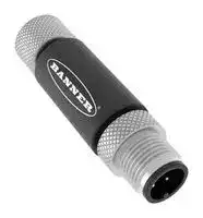


S15C-TMS-MQ
Signal Converter, Thermistor, Modbus, 1 Channels, 0.2 %, 30 VDC
- Manufacturer: BANNER ENGINEERING
- Product type: Signal Converters
- SVHC: No SVHC (15-Jan-2018)
- Accuracy %: 0.2%
- Product Range: S15C Series
- Supply Voltage: 30VDC
- Isolation Input: -
- No. of Channels: 1 Channel
- Output Accuracy: -
- No. of Output Channels: 1Channels
- Signal Conditioner Input: Thermistor
- Signal Conditioner Output: Modbus
- Signal Conditioner Mounting: Cable Mount
| Delivery and price | |
|---|---|
| Units per pack | 1 |
| Price | 128.8 € |
| Current stock | 10+ |
| Lead time | 30 days |
S15C Thermistor Temperature Probe to Mod bus® Converter Datasheet ## Features **==> picture [117 x 85] intentionally omitted <==** - Compact converter that connects to a thermistor probe and outputs the value to Modbus® registers - Thermistors are used as temperature sensors and are an accurate and costef fective sensor for measuring temperatures in various applications - • Rugged overmolded design meets IP65, IP67, and IP68 • Connects directly to a sensor or anywhere inline for ease of use ## Models Housing Function Female Male Connector S15 C - TMS - M Q C = Converter M = Modbus Q = Integral M12 quick disconnect The converter comes with the following included: Thermistor (Type G) with 2.9 m cable and M12 Quick Disconnect. Thermistor Ratings: Type G Cable length: 2.9 m Cable Material: PVC Tube/Thermistor: Copper Plated/PS103G2 Range: –20 °C to 105 °C (–4 °F to 221 °F) Accuracy: ± 0.2% ## Configuration Instructions ## Sensor Configuration Software The Sensor Configuration Software offers an easy way to manage converter Modbus settings, retrieve data, and visually show converter da ta. The Sensor Configuration Software runs on any Windows machine and uses an adapter cable (BWA-UCT-900, p/n 19970) to connect the converter to the computer. Download the most recent version of the Sensor Configuration Software from the Banner Engineering website: https:// info.bannerengineering.com/cs/groups/public/documents/software/b_3128586.exe. ## Modbus Configuration **==> picture [500 x 171] intentionally omitted <==** **----- Start of picture text -----**<br> Modbus Register Address Type Name I/O Range Description Notes Default<br>IO Data Out<br>40001 int16, Read IO Data Temperature °C = 4000 to +10500 Analog Data output 1 <br>Only<br>Temperature °C/°F = Da<br>40002 int16, Read IO Data Temperature °F = 4000 to +22100 ta Output ÷ 100 <br>Only Thermistor Resistance =<br>Data Output × 10<br>40003 int16, Read IO Data Thermistor Resistance = 70 to 23980 - -<br>Only<br>40004 int16, Read Only IO Error Status STATUS_ERROR_TYPE_NO_ERROR = 0STATUS_ERROR_TYPE_INVALID_THERM_TYPE = 1 Status of program 07 value <br>IO Data Rate<br>41201 int16, Read and Write Sample IO - Sample interval time for IO Minimum rate: 62.5 ms (0x01) 0x10 (1 sec)<br>Thermistor Input 1<br>Continued on page 2<br>**----- End of picture text -----**<br> Original Instructions September 08, 2023 p/n: 223253 Rev. E 223253 © Banner Engineering Corp. S15C Thermistor Temperature Probe to Modbus® Converter Datasheet **==> picture [500 x 144] intentionally omitted <==** **----- Start of picture text -----**<br> Continued from page 1<br>Modbus Register Address Type Name I/O Range Description Notes Default<br>41006 uint16, Read Thermistor THERM_TYPE_G_CURVE = 0 Selects which Thermistor type is 0 1 value, Thermistor 0<br>and Write curve Type THERM_TYPE_J_CURVE = 1 utilized. Only<br>COMs Settings<br>0 = 9.6k<br>46101 Baud Rate 1 = 19.2k 1<br>2 = 38.4k<br>0 = None<br>46102 Parity 1 = Odd - None<br>2 = Even<br>Modbus<br>46103 Slave Ad 1 to 247 - 1<br>dress<br>**----- End of picture text -----**<br> ## Wiring Diagrams **==> picture [500 x 167] intentionally omitted <==** **----- Start of picture text -----**<br> Female: Male:<br>1 1 (bn)<br>10 V DC to 30 V DC 10 V DC to 30 V DC<br>2 2 (wh)<br>Thermistor In RS485/D1/B/+<br>4 4 (bk)<br>RS485/D0/A/-<br>3 3 (bu)<br>Ground Ground<br>Male (Gateway) Female (Sensor) Pin Wire Color<br>1 Brown<br>1 2 2 White<br>2 1<br>3 Blue<br>4 3<br>3 4 4 Black<br>**----- End of picture text -----**<br> ## Status Indicators Power LED Indicator (Green) - Solid Green = Power On - • Off = Power Off Modbus Communication LED Indicator (Amber) - Flashing Amber = Modbus communications are active - • Off = Modbus communications are not present ## Specifications Supply Voltage 10 V DC to 30 V DC at 50 mA maximum Power Pass-Through Current 4 A maximum Supply Protection Circuitry Protected against reverse polarity and transient voltages Leakage Current Immunity 400 µA Resolution 12-bits Accuracy ± 1.5 °C (± 3 °F) Internal Resistance 100 ohms Indicators Green power Amber Modbus communications Connections Integral male/female 5pin M12 quickdisconnect connector Construction Coupling Material: Nickel-plated brass Connector Body: PVC translucent black ## Vibration and Mechanical Shock Meets IEC 60068-2-6 requirements (Vibration: 10 Hz to 55 Hz, 0.5 mm amplitude, 5 minutes sweep, 30 minutes dwell) Meets IEC 60068227 requirements (Shock: 15G 11 ms dura tion, half sine wave) Environmental Rating IP65, IP67, IP68 NEMA/UL Type 1 ## Operating Conditions Temperature: –40 °C to +70 °C (–40 °F to +158 °F) 90% at +70 °C maximum relative humidity (non-condensing) Storage Temperature: –40 °C to +80 °C (–40 °F to +176 °F) September 08, 2023 page 2 © Banner Engineering Corp. All rights reserved. S15C Thermistor Temperature Probe to Modbus® Converter Datasheet ## Thermistor Probe Cable length: 2.9 m Cable Material: PVC Tube/Thermistor: Copper Plated/PS103G2 Range: –20 °C to 105 °C (–4 °F to 221 °F) Accuracy: ± 0.2% ## Required Overcurrent Protection WARNING: Electrical connections must be made by qualified personnel in ac cordance with local and national electri cal codes and regulations. Certifications Banner Engineering BV Park Lane, Culliganlaan 2F bus 3 1831 Diegem, BELGIUM Overcurrent protection is required to be provided by end prod uct application per the supplied table. Overcurrent protection may be provided with external fusing or via Current Limiting, Class 2 Power Supply. Supply wiring leads < 24 AWG shall not be spliced. For additional product support, go to www.bannerengineering.com. Product Identification |Supply<br>Wiring<br>(AWG)<br>20|Required Overcurrent<br>Protection (A)<br>5.0|Required Overcurrent<br>Protection (A)<br>5.0|Supply<br>Wiring<br>(AWG)<br>26|Required Overcurrent<br>Protection (A)<br>1.0|Required Overcurrent<br>Protection (A)<br>1.0| |---|---|---|---|---|---| |22|3.0||28|0.8|| |24|1.0||30|0.5|| ## FCC Part 15 Class B This equipment has been tested and found to comply with the limits for a Class B digital device, pursuant to part 15 of the FCC Rules. These limits are designed to provide reasonable protection against harmful interference in a residential installation. This equipment generates, uses and can radiate radio frequency energy and, if not installed and used in accordance with the instructions, may cause harmful interference to radio communications. However, there is no guarantee that interference will not occur in a particular installation. If this equipment does cause harmful interference to radio or television reception, which can be determined by turning the equipment off and on, the user is encouraged to try to correct the interference by one or more of the following measures: - Reorient or relocate the receiving antenna. - Increase the separation between the equipment and receiver. - Connect the equipment into an outlet on a circuit different from that to which the receiver is connected. - Consult the dealer or an experienced radio/TV technician for help. ## Industry Canada ICES-003(B) This device complies with CAN ICES-3 (B)/NMB-3(B). Operation is subject to the following two conditions: 1) This device may not cause harmful interference; and 2) This device must accept any interference received, including interference that may cause undesired operation. Cet appareil est conforme à la norme NMB-3(B). Le fonctionnement est soumis aux deux conditions suivantes : (1) ce dispositif ne peut pas occasionner d'interférences, et (2) il doit tolérer toute interférence, y compris celles susceptibles de provoquer un fonctionnement non souhaité du dispositif. ## Dimensions All measurements are listed in millimeters [inches], unless noted otherwise. **==> picture [417 x 90] intentionally omitted <==** **----- Start of picture text -----**<br> 50<br>[1.97]<br>Approx.<br>27.9<br>4 [1.1]<br>[0.16] 2900<br>[114.2]<br>[0.79]20 Ø 3.2 M12 X 1 - 6h<br>[0.13]<br>**----- End of picture text -----**<br> September 08, 2023 page 3 © Banner Engineering Corp. All rights reserved. S15C Thermistor Temperature Probe to Modbus® Converter Datasheet ## Accessories ## Cordsets **==> picture [500 x 198] intentionally omitted <==** **----- Start of picture text -----**<br> 4Pin Threaded M12 Cordsets—Double Ended<br>Model Length Style Dimensions Pinout<br>MQDEC401SS 0.31 m (1 ft) Female<br>MQDEC-403SS 0.91 m (2.99 ft)<br>2<br>40 Typ.<br>MQDEC-406SS 1.83 m (6 ft) [1.58"] 1<br>MQDEC412SS 3.66 m (12 ft) 4 3<br>MQDEC420SS 6.10 m (20 ft) M12 x 1<br>MQDEC430SS 9.14 m (30.2 ft) Male Straight/Female ø 14.5 [0.57"] Male<br>Straight 44 Typ.<br>[1.73"] 1<br>2<br>4<br>MQDEC450SS 15.2 m (49.9 ft) M12 x 1 3<br>ø 14.5 [0.57"] 1 = Brown<br>2 = White<br>3 = Blue<br>4 = Black<br>**----- End of picture text -----**<br> ## Banner Engineering Corp Limited Warranty Banner Engineering Corp. warrants its products to be free from defects in material and workmanship for one year following the date of ship ment. Banner Engineering Corp. will repair or replace, free of charge, any product of its manufacture which, at the time it is returned to the factory, is found to have been defective during the warranty period. This warranty does not cover damage or liability for misuse, abuse, or the improper application or installation of the Banner product. THIS LIMITED WARRANTY IS EXCLUSIVE AND IN LIEU OF ALL OTHER WARRANTIES WHETHER EXPRESS OR IMPLIED (INCLUD ING, WITHOUT LIMITATION, ANY WARRANTY OF MERCHANTABILITY OR FITNESS FOR A PARTICULAR PURPOSE), AND WHETHER ARISING UNDER COURSE OF PERFORMANCE, COURSE OF DEALING OR TRADE USAGE. This Warranty is exclusive and limited to repair or, at the discretion of Banner Engineering Corp., replacement. IN NO EVENT SHALL BAN NER ENGINEERING CORP. BE LIABLE TO BUYER OR ANY OTHER PERSON OR ENTITY FOR ANY EXTRA COSTS, EXPENSES, LOSSES, LOSS OF PROFITS, OR ANY INCIDENTAL, CONSEQUENTIAL OR SPECIAL DAMAGES RESULTING FROM ANY PRODUCT DEFECT OR FROM THE USE OR INABILITY TO USE THE PRODUCT, WHETHER ARISING IN CONTRACT OR WARRANTY, STATUTE, TORT, STRICT LIABILITY, NEGLIGENCE, OR OTHERWISE. Banner Engineering Corp. reserves the right to change, modify or improve the design of the product without assuming any obligations or lia bilities relating to any product previously manufactured by Banner Engineering Corp. Any misuse, abuse, or improper application or installa tion of this product or use of the product for personal protection applications when the product is identified as not intended for such purposes will void the product warranty. Any modifications to this product without prior express approval by Banner Engineering Corp will void the prod uct warranties. All specifications published in this document are subject to change; Banner reserves the right to modify product specifications or update documentation at any time. Specifications and product information in English supersede that which is provided in any other lan guage. For the most recent version of any documentation, refer to: www.bannerengineering.com. For patent information, see www.bannerengineering.com/patents. September 08, 2023 page 4 © Banner Engineering Corp. All rights reserved.
Updated at April 23, 2026
Founded in 1966, Banner Engineering is a globally recognized leader in the design and manufacture of industrial automation products. The company is renowned for developing innovative, high-quality solutions that improve operational efficiency, safeguard personnel, and optimize manufacturing processes across a diverse range of industries. Our extensive selection of Banner Engineering components prominently features their industry-leading sensing technologies. We offer a comprehensive array of precision light sensors engineered for accurate detection and measurement in demanding environments. Complementing this core sensing portfolio is a robust offering of automation signaling devices, including visual signal indicator units and essential accessories, which provide clear and immediate communication of machine status. Beyond primary sensing and indication solutions, our range encompasses critical components for broader process control and machine safety. This includes advanced process controllers, reliable pressure sensors and transducers, and dependable safety relays. Supported by a variety of purpose-built sensor accessories and fiber optic lead assemblies, Banner Engineering delivers the durable, high-performance technologies required to build and maintain sophisticated automated systems.
About Novapart
Novapart is a B2B electronic component broker specialising in stock shortages and cost reduction. We source hard-to-find parts and identify compliant alternatives across a catalogue of 410,000+ components from 500+ manufacturers.
Learn more →Stock Shortage Specialist
When a component is unavailable, discontinued or has an unacceptable lead time, we tap into our network of vetted European and Asian distributors to source what you need — without compromising on quality or traceability.
Request a quote →Compliant Alternatives
We identify pin-to-pin, electrically equivalent substitutes that meet the same certifications (RoHS, AEC-Q100, REACH) as your original specification — validated against datasheets, not just part numbers. Often at a lower cost.
BOM Analysis service →