
Image not available
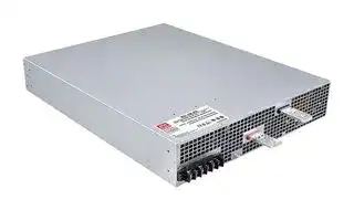
Illustrative purposes only

RST-15K-230
AC/DC Enclosed Power Supply (PSU), ITE & Industrial, 1 Outputs, 14.904 kW, 230 VDC, 69 A
⚠️ Reference pricing provided. In case of supply shortages, we will connect you with our trusted procurement partners to ensure your project's continuity.
- Manufacturer: MEAN WELL
- Product type: AC / DC Enclosed Power Supplies
- SVHC: No SVHC (25-Jun-2025)
- Product Range: RST-15K Series
- No. of Outputs: 1Outputs
- Output Power Max: 14.904kW
- Input Voltage VAC: 196V AC to 305V AC
- Power Supply Output Type: Programmable
- Output Current - Output 1: 69A
- Output Current - Output 2: -
- Output Current - Output 3: -
- Output Current - Output 4: -
- Output Voltage - Output 1: 230VDC
- Output Voltage - Output 2: -
- Output Voltage - Output 3: -
- Output Voltage - Output 4: -
- Power Supply Applications: ITE & Industrial
| Delivery and price | |
|---|---|
| Units per pack | 1 |
| Price | 3342.54 € |
| Current stock | 10+ |
| Lead time | 30 days |
Datasheet

> 15KW HVDC Single Output  Power Supply **RST- 15K series**

**==> picture [25 x 8] intentionally omitted <==**

**----- Start of picture text -----**<br>
Front<br>**----- End of picture text -----**<br>


**==> picture [24 x 9] intentionally omitted <==**

**----- Start of picture text -----**<br>
Back<br>**----- End of picture text -----**<br>


**==> picture [229 x 59] intentionally omitted <==**

**----- Start of picture text -----**<br>
BauarSicherheitbeegelodwacmat geprufto ges g<br>ED Ais www.ID 2000000000tuv.com<br>UL62368-1 BS EN/EN62368-1 TPTC004 IEC62368-1<br>■ Features<br>ψ △ ψ<br>**----- End of picture text -----**<br>


**==> picture [13 x 11] intentionally omitted <==**

**----- Start of picture text -----**<br>
■<br>**----- End of picture text -----**<br>


**==> picture [13 x 11] intentionally omitted <==**

**----- Start of picture text -----**<br>
■<br>**----- End of picture text -----**<br>


## ℃

**==> picture [13 x 11] intentionally omitted <==**

**----- Start of picture text -----**<br>
■<br>**----- End of picture text -----**<br>


_File Name:RST-15K-SPEC   2022-04-25_

**RST- 15K series**

15KW HVDC Single Output  Power Supply

## **SPECIFICATION**

## **MODEL**

|**MODEL**<br>**DC VOLTAGE**<br>**CURRENT (max.)**<br>**CURRENT RANGE**<br>**RATED POWER**<br>**FULL POWER VOLTAGE RANGE**<br>**OUTPUT**<br>**VOLTAGE ADJ. RANGE**<br>**LINE REGULATION**<br>**LOAD REGULATION**<br>**SETUP, RISE TIME**<br>**HOLD UP TIME (Typ.)**<br>**FREQUENCY RANGE**<br>**EFFICIENCY (Typ.)**<br>**Note.8**<br>**INPUT**<br>**INRUSH CURRENT (Typ.)**<br>**LEAKAGE CURRENT**<br>**OVER TEMPERATURE**<br>**WORKING TEMP.**<br>**WORKING HUMIDITY**<br>**STORAGE TEMP., HUMIDITY**<br>**TEMP. COEFFICIENT**<br>**VIBRATION**<br>**MTBF**<br>**DIMENSION**<br>**OTHERS**<br>**NOTE**<br>**PACKING**<br>**OVERLOAD**<br>**OVER VOLTAGE**<br>**AC CURRENT (Typ.)**<br>3000ms, 200ms at full load<br>47 ~ 63Hz<br>Phase voltage 196 ~ 305VAC<br>100 ~ 105% of rated current (overload protection value)<br>Protection type : Constant current limiting, unit will shutdown after 5 sec. re-power on to recover<br>Protection type : Shut down o/p voltage, re-power on to recover<br>-30 ~ +70<br>(Refer to "Derating Curve")<br>℃<br>20 ~ 90% RH non-condensing<br>-40 ~ +85<br>, 10 ~ 95% RH non-condensing<br>℃<br>±<br>℃<br>℃<br>0.03%/<br>(0 ~ 45<br>)<br>10 ~ 500Hz, 2G 10min./1cycle, 60min. each along X, Y, Z axes<br>25Kg; 1pcs/25Kg/2.82CUFT<br>121.9K hrs min.<br>Telcordia SR-332 (Bellcore) ; 16.2K hrs min.      MIL-HDBK-217F (25<br>)<br>℃<br>93.5%<br>145 ~ 166V<br>94%<br>273 ~ 312V<br>94.5%<br>420 ~ 480V<br>±0.5%<br>±0.5%<br>±0.5%<br>±0.5%<br>±0.5%<br>±0.5%<br>±1.0%<br>±1.0%<br>±1.0%<br>1Vp-p<br>2Vp-p<br>4Vp-p<br>90 ~ 138V<br>170 ~ 260V<br>260 ~ 400V<br>115V<br>230V<br>380V<br>130A<br>69A<br>45A<br>0 ~ 130A<br>0 ~ 69A<br>0 ~ 45A<br>14950W<br>115 ~ 138V<br>216 ~ 260V<br>334 ~ 400V<br>14904W<br>15030W<br>**RST-15K-115**<br>**RST-15K-230**<br>**RST-15K-380**<br>**POWER FACTOR (Typ.)**<br>≧<br>≧<br>0.98/230VAC(400VAC)/<br>0.97/277VAC(480VAC) at full load<br>**SAFETY STANDARDS**<br>**RIPPLE & NOISE (max.) Note.2**<br>**VOLTAGE TOLERANCE Note.3**<br>**WITHSTAND VOLTAGE**<br>**ISOLATION RESISTANCE**<br>I/P-O/P, I/P-FG, O/P-FG:100M Ohms / 500VDC / 25<br>/ 70% RH<br>℃<br>**ENVIRONMENT**<br>**SAFETY &**<br>**FUNCTION**<br>**EMC**<br>**(Note 7,9)**<br>**PROTECTION**<br>Shut down o/p voltage, recovers automatically after temperature goes down<br>**Parameter**<br>**Parameter**<br>ESD<br>Radiated<br>EFT / Burst<br>Surge<br>Conducted<br>Magnetic Field<br>Voltage Dips and Interruptions<br>Conducted<br>Radiated<br>Harmonic Current<br>Voltage Flicker<br>**Standard**<br>**Standard**<br>**Test Level / Note**<br>**Test Level / Note**<br>Level 3, 8KV air ; Level 2, 4KV contact<br>Level 3<br>Level 3<br>Level 3<br>Level 4<br>>95% dip 0.5 periods, 30% dip 25 periods,<br>>95% interruptions 250 periods<br>Class B<br>Class A<br>-----<br>-----<br>**EMC IMMUNITY**<br>**EMC EMISSION**<br>**ALARM SIGNAL OUTPUT**<br>**REMOTE ON-OFF CONTROL**<br>Please refer to the Function Manual<br>AC fail,DC OK, fan fail, OTP. Please refer to the Function Manual.<br>**CURRENT SHARING**<br>Up to 2 units. Please refer to the Function Manual<br>**OUTPUT VOLTAGE PROGRAMMABLE**<br>Can be adjusted via built-in potentiometer<br>Adjustment of output voltage is allowable to between 1 ~ 120% of nominal output voltage. Please refer to the PV curve Function Manual<br>Adjustment of constant current level is allowable to between 20 ~ 100% of rated current. Please refer to the Function Manual<br>**CONSTANT CURRENT LEVEL PROGRAMMABLE**<br>Level 4, 4KV/Line-Earth ; Level 3, 2KV/Line-Line<br>△<br>℃<br>ncludes set up tolerance,<br>derating curve<br>△<br>http://www.meanwell.com)<br>℃<br>℃<br>※<br>:<br>https://www.meanwell.com/serviceDisclaimer.aspx<br>16ms  230VAC/400VAC at 75% load          10ms / 230VAC/400VAC at full load<br>45A/230VAC(<br>)           26A/230VAC(<br>/ Y)<br>3<br>3-wire /<br>3<br>4-wire<br>ψ<br>△<br>ψ<br>150A/230VAC(<br>)           100A/230VAC(<br>/ Y)<br>3<br>3-wire /<br>3<br>4-wire<br>ψ<br>△<br>ψ<br><3.5mA /<br>305VAC(Y 530VAC)<br>△<br>I/P-O/P:4.3KVDC     I/P-FG:2.8KVDC     O/P-FG:2.8KVDC<br>540*424*83.5mm (L*W*H)<br>BS EN/EN55024 , BS EN/EN61204-3, BS EN/EN61000-6-2<br>BS EN/<br>BS EN/<br>EN55032 (CISPR32) /<br>EN55011 (CISPR11)<br>BS EN/<br>BS EN/<br>EN55032 (CISPR32) /<br>EN55011 (CISPR11)<br>BS EN/EN61000-3-12<br>BS EN/EN61000-3-3<br>BS EN/EN61000-4-2<br>BS EN/EN61000-4-3<br>BS EN/EN61000-4-4<br>BS EN/EN61000-4-5<br>BS EN/EN61000-4-6<br>BS EN/EN61000-4-8<br>BS EN/EN61000-4-11<br>UL62368-1, CAN/CSA C22.2<br>, TUV BS EN/EN62368-1, EAC TP TC 004 approved<br>No. 62368-1<br>**VOLTAGE RANGE**<br>1. All parameters NOT specially mentioned are measured at<br>230VAC(Y 400VAC) input, rated load and 25<br>of ambient temperature.<br>2. Ripple & noise are measured at 2OMHz of bandwidth by using a 12" twisted pair-wire terminated with a 0.1uf & 47uf parallel capacitor.<br>3. Tolerance<br>line regulation and load regulation.<br>4. Derating may be needed under low input voltages. Please check the<br>for more details.<br>5. Without fan cooling to provide adequate heat dissipation, OTP might be triggered if trimming output voltage by PV signal toward upper or bottom limits of<br>nominal voltage. Under such condition, enhanced cooling on PSU is highly recommended.<br>6. If use PV signal to adjust Vo, under creatin operation conditions, ripple noise of Vo might go over rating defined in this specification.<br>7. Need additional EMI filter to meet regulations of EMC conducted and radiated emission. Characteristics of EMI filter please refer to the table, Minimum<br>Insertion Loss.<br>8. The efficiency is measured at<br>: 230VAC/Y: 400VAC input. The efficiency level is measured at output voltage 115V(115V model)/216V(230V model)/<br>334V(380V model).<br>9. The power supply is considered a component which will be installed into a final equipment. All the EMC tests are been executed by mounting the unit on<br>a 600mm*900mm metal plate with 1mm of thickness. The final equipment must be re-confirmed that it still meets EMC directives. For guidance on how to<br>perform these EMC tests, please refer to “EMI testing of component power supplies.” (as available on<br>10. The ambient temperature derating of 3.55<br>/1000m with fanless models and of 5<br>/1000m with fan models for operating altitude higher than 2000m(6500ft).<br>Product Liability Disclaimer<br>For detailed information, please refer to|**MODEL**<br>**DC VOLTAGE**<br>**CURRENT (max.)**<br>**CURRENT RANGE**<br>**RATED POWER**<br>**FULL POWER VOLTAGE RANGE**<br>**OUTPUT**<br>**VOLTAGE ADJ. RANGE**<br>**LINE REGULATION**<br>**LOAD REGULATION**<br>**SETUP, RISE TIME**<br>**HOLD UP TIME (Typ.)**<br>**FREQUENCY RANGE**<br>**EFFICIENCY (Typ.)**<br>**Note.8**<br>**INPUT**<br>**INRUSH CURRENT (Typ.)**<br>**LEAKAGE CURRENT**<br>**OVER TEMPERATURE**<br>**WORKING TEMP.**<br>**WORKING HUMIDITY**<br>**STORAGE TEMP., HUMIDITY**<br>**TEMP. COEFFICIENT**<br>**VIBRATION**<br>**MTBF**<br>**DIMENSION**<br>**OTHERS**<br>**NOTE**<br>**PACKING**<br>**OVERLOAD**<br>**OVER VOLTAGE**<br>**AC CURRENT (Typ.)**<br>3000ms, 200ms at full load<br>47 ~ 63Hz<br>Phase voltage 196 ~ 305VAC<br>100 ~ 105% of rated current (overload protection value)<br>Protection type : Constant current limiting, unit will shutdown after 5 sec. re-power on to recover<br>Protection type : Shut down o/p voltage, re-power on to recover<br>-30 ~ +70<br>(Refer to "Derating Curve")<br>℃<br>20 ~ 90% RH non-condensing<br>-40 ~ +85<br>, 10 ~ 95% RH non-condensing<br>℃<br>±<br>℃<br>℃<br>0.03%/<br>(0 ~ 45<br>)<br>10 ~ 500Hz, 2G 10min./1cycle, 60min. each along X, Y, Z axes<br>25Kg; 1pcs/25Kg/2.82CUFT<br>121.9K hrs min.<br>Telcordia SR-332 (Bellcore) ; 16.2K hrs min.      MIL-HDBK-217F (25<br>)<br>℃<br>93.5%<br>145 ~ 166V<br>94%<br>273 ~ 312V<br>94.5%<br>420 ~ 480V<br>±0.5%<br>±0.5%<br>±0.5%<br>±0.5%<br>±0.5%<br>±0.5%<br>±1.0%<br>±1.0%<br>±1.0%<br>1Vp-p<br>2Vp-p<br>4Vp-p<br>90 ~ 138V<br>170 ~ 260V<br>260 ~ 400V<br>115V<br>230V<br>380V<br>130A<br>69A<br>45A<br>0 ~ 130A<br>0 ~ 69A<br>0 ~ 45A<br>14950W<br>115 ~ 138V<br>216 ~ 260V<br>334 ~ 400V<br>14904W<br>15030W<br>**RST-15K-115**<br>**RST-15K-230**<br>**RST-15K-380**<br>**POWER FACTOR (Typ.)**<br>≧<br>≧<br>0.98/230VAC(400VAC)/<br>0.97/277VAC(480VAC) at full load<br>**SAFETY STANDARDS**<br>**RIPPLE & NOISE (max.) Note.2**<br>**VOLTAGE TOLERANCE Note.3**<br>**WITHSTAND VOLTAGE**<br>**ISOLATION RESISTANCE**<br>I/P-O/P, I/P-FG, O/P-FG:100M Ohms / 500VDC / 25<br>/ 70% RH<br>℃<br>**ENVIRONMENT**<br>**SAFETY &**<br>**FUNCTION**<br>**EMC**<br>**(Note 7,9)**<br>**PROTECTION**<br>Shut down o/p voltage, recovers automatically after temperature goes down<br>**Parameter**<br>**Parameter**<br>ESD<br>Radiated<br>EFT / Burst<br>Surge<br>Conducted<br>Magnetic Field<br>Voltage Dips and Interruptions<br>Conducted<br>Radiated<br>Harmonic Current<br>Voltage Flicker<br>**Standard**<br>**Standard**<br>**Test Level / Note**<br>**Test Level / Note**<br>Level 3, 8KV air ; Level 2, 4KV contact<br>Level 3<br>Level 3<br>Level 3<br>Level 4<br>>95% dip 0.5 periods, 30% dip 25 periods,<br>>95% interruptions 250 periods<br>Class B<br>Class A<br>-----<br>-----<br>**EMC IMMUNITY**<br>**EMC EMISSION**<br>**ALARM SIGNAL OUTPUT**<br>**REMOTE ON-OFF CONTROL**<br>Please refer to the Function Manual<br>AC fail,DC OK, fan fail, OTP. Please refer to the Function Manual.<br>**CURRENT SHARING**<br>Up to 2 units. Please refer to the Function Manual<br>**OUTPUT VOLTAGE PROGRAMMABLE**<br>Can be adjusted via built-in potentiometer<br>Adjustment of output voltage is allowable to between 1 ~ 120% of nominal output voltage. Please refer to the PV curve Function Manual<br>Adjustment of constant current level is allowable to between 20 ~ 100% of rated current. Please refer to the Function Manual<br>**CONSTANT CURRENT LEVEL PROGRAMMABLE**<br>Level 4, 4KV/Line-Earth ; Level 3, 2KV/Line-Line<br>△<br>℃<br>ncludes set up tolerance,<br>derating curve<br>△<br>http://www.meanwell.com)<br>℃<br>℃<br>※<br>:<br>https://www.meanwell.com/serviceDisclaimer.aspx<br>16ms  230VAC/400VAC at 75% load          10ms / 230VAC/400VAC at full load<br>45A/230VAC(<br>)           26A/230VAC(<br>/ Y)<br>3<br>3-wire /<br>3<br>4-wire<br>ψ<br>△<br>ψ<br>150A/230VAC(<br>)           100A/230VAC(<br>/ Y)<br>3<br>3-wire /<br>3<br>4-wire<br>ψ<br>△<br>ψ<br><3.5mA /<br>305VAC(Y 530VAC)<br>△<br>I/P-O/P:4.3KVDC     I/P-FG:2.8KVDC     O/P-FG:2.8KVDC<br>540*424*83.5mm (L*W*H)<br>BS EN/EN55024 , BS EN/EN61204-3, BS EN/EN61000-6-2<br>BS EN/<br>BS EN/<br>EN55032 (CISPR32) /<br>EN55011 (CISPR11)<br>BS EN/<br>BS EN/<br>EN55032 (CISPR32) /<br>EN55011 (CISPR11)<br>BS EN/EN61000-3-12<br>BS EN/EN61000-3-3<br>BS EN/EN61000-4-2<br>BS EN/EN61000-4-3<br>BS EN/EN61000-4-4<br>BS EN/EN61000-4-5<br>BS EN/EN61000-4-6<br>BS EN/EN61000-4-8<br>BS EN/EN61000-4-11<br>UL62368-1, CAN/CSA C22.2<br>, TUV BS EN/EN62368-1, EAC TP TC 004 approved<br>No. 62368-1<br>**VOLTAGE RANGE**<br>1. All parameters NOT specially mentioned are measured at<br>230VAC(Y 400VAC) input, rated load and 25<br>of ambient temperature.<br>2. Ripple & noise are measured at 2OMHz of bandwidth by using a 12" twisted pair-wire terminated with a 0.1uf & 47uf parallel capacitor.<br>3. Tolerance<br>line regulation and load regulation.<br>4. Derating may be needed under low input voltages. Please check the<br>for more details.<br>5. Without fan cooling to provide adequate heat dissipation, OTP might be triggered if trimming output voltage by PV signal toward upper or bottom limits of<br>nominal voltage. Under such condition, enhanced cooling on PSU is highly recommended.<br>6. If use PV signal to adjust Vo, under creatin operation conditions, ripple noise of Vo might go over rating defined in this specification.<br>7. Need additional EMI filter to meet regulations of EMC conducted and radiated emission. Characteristics of EMI filter please refer to the table, Minimum<br>Insertion Loss.<br>8. The efficiency is measured at<br>: 230VAC/Y: 400VAC input. The efficiency level is measured at output voltage 115V(115V model)/216V(230V model)/<br>334V(380V model).<br>9. The power supply is considered a component which will be installed into a final equipment. All the EMC tests are been executed by mounting the unit on<br>a 600mm*900mm metal plate with 1mm of thickness. The final equipment must be re-confirmed that it still meets EMC directives. For guidance on how to<br>perform these EMC tests, please refer to “EMI testing of component power supplies.” (as available on<br>10. The ambient temperature derating of 3.55<br>/1000m with fanless models and of 5<br>/1000m with fan models for operating altitude higher than 2000m(6500ft).<br>Product Liability Disclaimer<br>For detailed information, please refer to|**RST-15K-115**|**RST-15K-230**|**RST-15K-380**|
|---|---|---|---|---|
||**DC VOLTAGE**|115V|230V|380V|
||**CURRENT (max.)**|130A|69A|45A|
||**CURRENT RANGE**|0 ~ 130A|0 ~ 69A|0 ~ 45A|
||**RATED POWER**|14950W|14904W|15030W|
||**FULL POWER VOLTAGE RANGE**|115 ~ 138V|216 ~ 260V|334 ~ 400V|
||**RIPPLE & NOISE (max.) Note.2**|1Vp-p|2Vp-p|4Vp-p|
||**VOLTAGE ADJ. RANGE**|90 ~ 138V<br>170 ~ 260V<br>260 ~ 400V<br>Can be adjusted via built-in potentiometer|||
||**VOLTAGE TOLERANCE Note.3**|±1.0%|±1.0%|±1.0%|
||**LINE REGULATION**|±0.5%|±0.5%|±0.5%|
||**LOAD REGULATION**|±0.5%|±0.5%|±0.5%|
||**SETUP, RISE TIME**|3000ms, 200ms at full load|||
||**HOLD UP TIME (Typ.)**|16ms  230VAC/400VAC at 75% load          10ms / 230VAC/400VAC at full load|||
||**VOLTAGE RANGE**|Phase voltage 196 ~ 305VAC|||
||**FREQUENCY RANGE**|47 ~ 63Hz|||
||**POWER FACTOR (Typ.)**|≧<br>≧<br>0.98/230VAC(400VAC)/<br>0.97/277VAC(480VAC) at full load|||
||**EFFICIENCY (Typ.)**<br>**Note.8**|93.5%|94%|94.5%|
||**AC CURRENT (Typ.)**|45A/230VAC(<br>)           26A/230VAC(<br>/ Y)<br>3<br>3-wire /<br>3<br>4-wire<br>ψ<br>△<br>ψ|||
||**INRUSH CURRENT (Typ.)**|150A/230VAC(<br>)           100A/230VAC(<br>/ Y)<br>3<br>3-wire /<br>3<br>4-wire<br>ψ<br>△<br>ψ|||
||**LEAKAGE CURRENT**|<3.5mA /<br>305VAC(Y 530VAC)<br>△|||
||**OVERLOAD**|100 ~ 105% of rated current (overload protection value)<br>Protection type : Constant current limiting, unit will shutdown after 5 sec. re-power on to recover|||
||**OVER VOLTAGE**|Protection type : Shut down o/p voltage, re-power on to recover<br>145 ~ 166V<br>273 ~ 312V<br>420 ~ 480V|||
||**OVER TEMPERATURE**|Shut down o/p voltage, recovers automatically after temperature goes down|||
||**CURRENT SHARING**|Up to 2 units. Please refer to the Function Manual|||
||**OUTPUT VOLTAGE PROGRAMMABLE**|Adjustment of output voltage is allowable to between 1 ~ 120% of nominal output voltage. Please refer to the PV curve Function Manual|||
||**CONSTANT CURRENT LEVEL PROGRAMMABLE**|Adjustment of constant current level is allowable to between 20 ~ 100% of rated current. Please refer to the Function Manual|||
||**REMOTE ON-OFF CONTROL**|Please refer to the Function Manual|||
||**ALARM SIGNAL OUTPUT**|AC fail,DC OK, fan fail, OTP. Please refer to the Function Manual.|||
||**WORKING TEMP.**|-30 ~ +70<br>(Refer to "Derating Curve")<br>℃|||
||**WORKING HUMIDITY**|20 ~ 90% RH non-condensing|||
||**STORAGE TEMP., HUMIDITY**|-40 ~ +85<br>, 10 ~ 95% RH non-condensing<br>℃|||
||**TEMP. COEFFICIENT**|±<br>℃<br>℃<br>0.03%/<br>(0 ~ 45<br>)|||
||**VIBRATION**|10 ~ 500Hz, 2G 10min./1cycle, 60min. each along X, Y, Z axes|||
||**SAFETY STANDARDS**|UL62368-1, CAN/CSA C22.2<br>, TUV BS EN/EN62368-1, EAC TP TC 004 approved<br>No. 62368-1|||
||**WITHSTAND VOLTAGE**|I/P-O/P:4.3KVDC     I/P-FG:2.8KVDC     O/P-FG:2.8KVDC|||
||**ISOLATION RESISTANCE**|I/P-O/P, I/P-FG, O/P-FG:100M Ohms / 500VDC / 25<br>/ 70% RH<br>℃|||
||**MTBF**<br>**EMC IMMUNITY**<br>**EMC EMISSION**|**Parameter**|**Standard**|**Test Level / Note**|
|||Conducted|BS EN/<br>BS EN/<br>EN55032 (CISPR32) /<br>EN55011 (CISPR11)|Class B|
|||Radiated|BS EN/<br>BS EN/<br>EN55032 (CISPR32) /<br>EN55011 (CISPR11)|Class A|
|||Harmonic Current|BS EN/EN61000-3-12|-----|
|||Voltage Flicker|BS EN/EN61000-3-3|-----|
|||BS EN/EN55024 , BS EN/EN61204-3, BS EN/EN61000-6-2|||
|||**Parameter**|**Standard**|**Test Level / Note**|
|||ESD|BS EN/EN61000-4-2|Level 3, 8KV air ; Level 2, 4KV contact|
|||Radiated|BS EN/EN61000-4-3|Level 3|
|||EFT / Burst|BS EN/EN61000-4-4|Level 3|
|||Surge|BS EN/EN61000-4-5|Level 4, 4KV/Line-Earth ; Level 3, 2KV/Line-Line|
|||Conducted|BS EN/EN61000-4-6|Level 3|
|||Magnetic Field|BS EN/EN61000-4-8|Level 4|
|||Voltage Dips and Interruptions|BS EN/EN61000-4-11|>95% dip 0.5 periods, 30% dip 25 periods,<br>>95% interruptions 250 periods|
|||121.9K hrs min.<br>Telcordia SR-332 (Bellcore) ; 16.2K hrs min.      MIL-HDBK-217F (25<br>)<br>℃|||
||**DIMENSION**|540*424*83.5mm (L*W*H)|||
||**PACKING**<br>25Kg; 1pcs/25Kg/2.82CUFT<br>△<br>℃<br>ncludes set up tolerance,<br>derating curve<br>△<br>http://www.meanwell.com)<br>℃<br>℃<br>※<br>:<br>https://www.meanwell.com/serviceDisclaimer.aspx<br>1. All parameters NOT specially mentioned are measured at<br>230VAC(Y 400VAC) input, rated load and 25<br>of ambient temperature.<br>2. Ripple & noise are measured at 2OMHz of bandwidth by using a 12" twisted pair-wire terminated with a 0.1uf & 47uf parallel capacitor.<br>3. Tolerance<br>line regulation and load regulation.<br>4. Derating may be needed under low input voltages. Please check the<br>for more details.<br>5. Without fan cooling to provide adequate heat dissipation, OTP might be triggered if trimming output voltage by PV signal toward upper or bottom limits of<br>nominal voltage. Under such condition, enhanced cooling on PSU is highly recommended.<br>6. If use PV signal to adjust Vo, under creatin operation conditions, ripple noise of Vo might go over rating defined in this specification.<br>7. Need additional EMI filter to meet regulations of EMC conducted and radiated emission. Characteristics of EMI filter please refer to the table, Minimum<br>Insertion Loss.<br>8. The efficiency is measured at<br>: 230VAC/Y: 400VAC input. The efficiency level is measured at output voltage 115V(115V model)/216V(230V model)/<br>334V(380V model).<br>9. The power supply is considered a component which will be installed into a final equipment. All the EMC tests are been executed by mounting the unit on<br>a 600mm*900mm metal plate with 1mm of thickness. The final equipment must be re-confirmed that it still meets EMC directives. For guidance on how to<br>perform these EMC tests, please refer to “EMI testing of component power supplies.” (as available on<br>10. The ambient temperature derating of 3.55<br>/1000m with fanless models and of 5<br>/1000m with fan models for operating altitude higher than 2000m(6500ft).<br>Product Liability Disclaimer<br>For detailed information, please refer to||||


△

http://www.meanwell.com)

10. The ambient temperature derating of 3.55 ℃ /1000m with fanless models and of 5 ℃ /1000m with fan models for operating altitude higher than 2000m(6500ft). ※ Product Liability Disclaimer : For detailed information, please refer to https://www.meanwell.com/serviceDisclaimer.aspx

_File Name:RST-15K-SPEC 2022-04-25_

**RST - 15K series**

## 15KW HVDC Single Output  Power Supply

## **Block Diagram**

**==> picture [451 x 263] intentionally omitted <==**

**----- Start of picture text -----**<br>
PFC fosc : 65KHz<br>PWM fosc : 85KHz<br>EMI RECTIFIERS POWER RECTIFIERS +V<br>I/P FILTER & SWITCHING & -V<br>PFC FILTER<br>O.T.P. DETECTION<br>PFC CIRCUIT<br>FG<br>CONTROL<br>CONTROL CURRENT<br>CIRCUIT LIMIT<br>O.V.P.<br>CS<br>PV<br>PC<br>Remote ON/OFF<br>ISOLATOR DC-OK<br>& AC-FAIL<br>RELAY FAN-FAIL<br>OTP<br>AUX RECTIFIERS AUX POWER(+12V/0.1A)<br>POWER FILTER& Only for remote ON-OFF<br>control<br>FAN<br>**----- End of picture text -----**<br>


**==> picture [465 x 181] intentionally omitted <==**

**----- Start of picture text -----**<br>
DERATING CURVE (TBC) STATIC CHARACTERISTICS<br>100<br>100<br>90<br>75 230VAC<br>Input only 80<br>60<br>40 70<br>60<br>30<br>50<br>196 210 220 230 240 250 260 270 280 290 305<br>-30 -25 0 20 30 45 70 (HORIZONTAL)<br>INPUT VOLTAGE (V) 60Hz<br>AMBIENT TEMPERATURE ( ℃ )<br>LOAD (%) LOAD (%)<br>**----- End of picture text -----**<br>


_File Name:RST-15K-SPEC   2022-04-25_

**RST - 15K series**

15KW HVDC Single Output  Power Supply

## **EFFICIENCY VS LOAD (380V MODEL)**

**==> picture [292 x 135] intentionally omitted <==**

**----- Start of picture text -----**<br>
100<br>92<br>90<br>480VAC& 334VDC<br>85<br>400VAC& 334VDC<br>80<br>480VAC & 380VDC<br>75<br>400VAC& 380VDC<br>70<br>65<br>10% 20% 30% 40% 50% 60% 70% 80% 90% 100%<br>LOAD<br>EFFICIENCY (%)<br>**----- End of picture text -----**<br>


## **AC Power Connection**

**==> picture [348 x 307] intentionally omitted <==**

**----- Start of picture text -----**<br>
◎ψ3 3-wire / △ 230VAC<br>T RST-15K<br>N3<br>L3<br>N2<br>L2<br>N1<br>L1<br>S<br>R FG<br>Fig 1.1<br>◎ψ3 4-wire / Y 400VAC<br>T RST-15K<br>N3<br>L3<br>N2<br>N L2<br>N1<br>L1<br>S<br>R FG<br>Fig 1.2<br>230V<br>230V<br>230V<br>400V<br>**----- End of picture text -----**<br>


■Note : RST-15K can also be operated by 1ψ2-wire 196~305VAC input. Please refer to the connection diagram below. Operating with 1ψ2-wire may lead to certain characteristics different from the specification, such as the larger Ripple and Noise. Should there be any issues, please contact MEAN WELL.

**==> picture [244 x 113] intentionally omitted <==**

**----- Start of picture text -----**<br>
L RST-15K<br>N3<br>L3<br>N2<br>L2<br>N1<br>L1<br>N FG<br>230V<br>**----- End of picture text -----**<br>


Fig 1.3

_File Name:RST-15K-SPEC   2022-04-25_

**RST - 15K series**

15KW HVDC Single Output  Power Supply

## **Function Manual**

- **1.Output Voltage Programming (or, PV / remote voltage programming / remote adjust / margin programming / dynamic voltage trim)**

**==> picture [404 x 66] intentionally omitted <==**

**----- Start of picture text -----**<br>
(1)by potentiometer (SVR) ON 1 2 3<br>(a)Have the DIP switch position-3 set as OFF<br>(b)Output voltage can be trimmed by SVR.<br>(2)by Output Voltage Programming ON 1 2 3<br>(a)Have the DIP switch position-3 set as OFF<br>(b)The output voltage can be trimmed to 1~120% by applying EXTERNAL VOLTAGE between PV+ and PV- on CN26 or CN27.<br>**----- End of picture text -----**<br>


**==> picture [481 x 395] intentionally omitted <==**

**----- Start of picture text -----**<br>
+V<br>-V<br>SVR DIP SW<br>CN26 CN27 CN22 CN25<br>CN26 +V<br>SVR<br>DIP LOAD<br>SWITCH<br>-V<br>PIN4 PV- PIN6 PV+<br>EXTERNAL VOLTAGE (DC)<br>Fig 1.1<br>100<br>Vout 83.3<br>80<br>120<br>60<br>100<br>40<br>Non-Linear 20<br>V<br>1.4 115 138<br>115V<br>1 2.3 216 260<br>230V<br>V 3.8 334 400<br>0 1 4.74.8 380V<br>EXTERNAL VOLTAGE (DC) OUTPUT VOLTAGE<br>◎ The rated current should change with the Output Voltage Programming accordingly.<br>OUTPUT  VOLTAGE(%)<br>OUTPUT CURRENT (%)<br>**----- End of picture text -----**<br>


**==> picture [18 x 7] intentionally omitted <==**

**----- Start of picture text -----**<br>
Fig 1.2<br>**----- End of picture text -----**<br>


_File Name:RST-15K-SPEC   2022-04-25_

**RST - 15K series**

15KW HVDC Single Output  Power Supply

## **2.Constant Current Programming (or, PC / remote current programming / dynamic current trim)**

**==> picture [486 x 65] intentionally omitted <==**

**----- Start of picture text -----**<br>
(1)Default Overload Protection(OLP) 100~105% of rated current<br>1 2 3<br>(a)Have the DIP switch position-2 set as ON<br>(b)Output current is set default value. OFF<br>(2)by Constant Current Level Programming ON 1 2 3<br>(a)Have the DIP switch position-2 set as OFF<br>(b)The constant current level can be trimmed to 20~100% of the rated current by applying EXTERNAL VOLTAGE between PC+ and PC- on CN26 or CN27.<br>**----- End of picture text -----**<br>


**==> picture [476 x 334] intentionally omitted <==**

**----- Start of picture text -----**<br>
+V<br>-V<br>SVR DIP SW<br>CN26 CN27 CN22 CN25<br>CN26 +V<br>LOAD<br>-V<br>PIN3 PC- PIN5 PC+<br>EXTERNAL VOLTAGE (DC)<br>Fig 2.1<br>Iout<br>110<br>100<br>Non-Linear<br>20<br>V<br>0 1 4.7 4.8<br>EXTERNAL VOLTAGE (DC)<br>Fig 2.2<br>OUTPUT  CURRENT(%)<br>**----- End of picture text -----**<br>


- Output will shut down after O/P voltage is below < 80% of Vset for 6 sec, re-power on to recover.

## **3.Select Overload Protection (OLP) Mode**

(1)Continuous Constant Current mode 1 2 3 ON Have the DIPswitch position-1 set as                   ,and RST-15K will work in continuous constant current mode when the output is overloaded andOFF the output voltage is greater than 50% of the rated output voltage. (2)Delay Shutdown mode 1 2 3 ON Have the DIPswitch position-1 set as                   ,and RST-15K will shut down after 5 seconds of constant current operation, when the output isOFF overloaded or short-circuited.

_File Name:RST-15K-SPEC   2022-04-25_

**RST - 15K series**

## 15KW HVDC Single Output  Power Supply

## **4.Remote ON-OFF Control**

**==> picture [270 x 9] intentionally omitted <==**

**----- Start of picture text -----**<br>
※ The power supply can be turned ON-OFF by using the "Remote ON-OFF" function.<br>**----- End of picture text -----**<br>


**==> picture [468 x 248] intentionally omitted <==**

**----- Start of picture text -----**<br>
Between Remote ON-OFF ( CN25 pin 5) and 12V-AUX( CN25 pin1 ) Output Status<br>Switch close (Short) power supply ON<br>Switch open (Open) power supply OFF<br>Table 4.1<br>SW<br>12V-AUX<br>+V RC+<br>RST-15K<br>RC-<br>-V GND-AUX<br>SVR DIP SW<br>CN26 CN27 CN22 CN25<br>PIN1 12V-AUX<br>PIN5 RC+<br>Fig 4.1<br>CN25<br>PIN6 RC-<br>PIN2 GND-AUX<br>**----- End of picture text -----**<br>


## **5.Alarm Signal Output**

- ※ There are 4 alarm signals on CN22, and each signal can select two types of output circuit.

- (1)Relay contact output {OTP1, OTP1-GND) ; (DC-OK1, DC-OK1-GND) ; (AC-FAIL1-GND, AC-FAIL1) ; (FAN-FAIL1-GND, FAN-FAIL1)} Normally open contact. "Short" when the alarm arises. Relay contact rating(maximum) is 30V/1A resistive.

**==> picture [84 x 75] intentionally omitted <==**

**----- Start of picture text -----**<br>
R<br>V<br>Fig 5.1<br>**----- End of picture text -----**<br>


- (2)Open collector output {DC-OK2-GND, DC-OK2) ; (AC-FAIL2-GND, AC-FAIL2) ; (OTP2, OTP2-GND) ; (FAN-FAIL2, FAN-FAIL2-GND)} An external voltage source is required for this function that is shown in Fig 5.2. These signals are isolated from output. The maximum sink current is 10mA and the maximum external voltage is 20V (there is a built-in 24V zener diode in inner circuitry).

**==> picture [332 x 175] intentionally omitted <==**

**----- Start of picture text -----**<br>
12V-AUX 10KΩ x4pcs<br>DC-OK2<br>DC-OK2-GND<br>AC-FAIL2<br>RST-15K AC-FAIL2-GND<br>Application<br>OTP2<br>Circuit<br>OTP2-GND<br>FAN-FAIL2<br>FAN-FAIL2-GND<br>GND-AUX<br>Fig 5.2<br>**----- End of picture text -----**<br>


_File Name:RST-15K-SPEC   2022-04-25_

**RST - 15K series**

## 15KW HVDC Single Output  Power Supply

## **6.Current Sharing**

RST-15K has the built-in active current sharing function and can be connected in parallel, up to 2 units, to provide higher output power as exhibited below :

- ※ The voltage difference among each output should be minimized that less than 0.2V is required.

- ※ The total output current must not exceed the value determined by the following equation.

   - Maximum output current at parallel operation=(The rated current per unit)x(Number of unit)x0.95

- ※ When the total output current is less than 5% of the total rated current, or say (5% of Rated current per unit)×(Number of unit) the current shared among units may not be fully balanced.

**==> picture [310 x 286] intentionally omitted <==**

**----- Start of picture text -----**<br>
+V<br>-V<br>SVR DIP SW<br>CN26 CN27 CN22 CN25<br>+V<br>Load<br>-V<br>+V<br>-V<br>SVR DIP SW<br>CN26 CN27 CN22 CN25<br>**----- End of picture text -----**<br>


- CS+, CS- and RC+, RC- are connected mutually in parallel.

_File Name:RST-15K-SPEC   2022-04-25_

## 15KW HVDC Single Output  Power Supply

## **RST - 15K series**

**==> picture [506 x 635] intentionally omitted <==**

**----- Start of picture text -----**<br>
Mechanical Specification Case No.234B     Unit:mm<br>540<br>488 21<br>1 CN26 CN27 CN22 CN25<br>1 1 3 5 1 3 5 1 3 5 7 9 11 13 15 1 3 5 7<br>2 4 6 2 4 6 2 4 6 8 10 12 14 16 2 4 6 8<br>4-M4 L=5mm 1<br>68.75 7.4 LED SVR<br>406 102.9<br>8-M4 L=5mm<br>1 1<br>60<br>+V<br>1 1<br>Air flow 2-M3<br>direction<br>-V<br>1 1<br>TB1<br>1<br>2<br>3<br>4<br>5<br>1 1 6<br>22max<br>7 7.1<br>540<br>488 21<br>1<br>1<br>4-M4 L=5mm Screw "A" 1<br>※ Mounting Instruction Chassis of RST-15K<br>Hole No. Recommended Screw Size MAX. Penetration Depth  L Recommended mounting torque Mounting Surface<br>1 M4 5mm 7~1  K0 gf-cm<br>※ Control Pin No. Assignment (CN26,CN27) : HRS DF11-06DP-2DS or equivalent<br>Mounting Screw<br>1 5<br>L<br>Mating Housing HRS DF11-06DS or equivalent<br>Terminal HRS DF11-**SC or equivalent<br>2 6<br>◎ CN26 and CN27 are connected internally.<br>Pin No. Function Description<br>1 CS- Current sharing signal. When units are connected in parallel, the CS pins of the units should be connected to allow current balance<br>2 CS+ between units.<br>3 PC- Connection for output current programming.<br>4 PV- Connection for output voltage programming.<br>5 PC+ Connection for output current programming.<br>6 PV+ Connection for output voltage programming.<br>2<br>-ψ<br>8.5<br>DIP-SW<br>SVR<br>LED<br>10.2<br>10<br>13<br>38 83.5<br>38<br>45.5 45.5<br>120 120<br>30<br>483.6 466.1 91.6 91.6 424<br>120 120<br>22.7<br>22.7<br>CN25<br>CN22<br>CN27<br>CN27<br>ON 321 CN26<br>**----- End of picture text -----**<br>


_File Name:RST-15K-SPEC   2022-04-25_

**RST - 15K series**

15KW HVDC Single Output  Power Supply

|※Control Pin No.|※Control Pin No.|※Control Pin No.|※Control Pin No.|※Control Pin No.|※Control Pin No.|※Control Pin No.|※Control Pin No.|※Control Pin No.|※Control Pin No.|※Control Pin No.|※Control Pin No.|Assignment<br>: HRS DF11-16DP-2DS or equivalent<br>(<br>)<br>CN22|Assignment<br>: HRS DF11-16DP-2DS or equivalent<br>(<br>)<br>CN22|Assignment<br>: HRS DF11-16DP-2DS or equivalent<br>(<br>)<br>CN22|Assignment<br>: HRS DF11-16DP-2DS or equivalent<br>(<br>)<br>CN22|Assignment<br>: HRS DF11-16DP-2DS or equivalent<br>(<br>)<br>CN22||||
|---|---|---|---|---|---|---|---|---|---|---|---|---|---|---|---|---|---|---|---|
|||||1||||||15||||||||||
|||||||||||||||||Mating Housing<br>HRS DF11-16DS or equivalent||||
|||||||||||||||||Terminal<br>HRS DF11-**SC|or equivalent|||
|||||||||||||||||||||
|||||2||||||16||||||||||
|||Pin No.|||||||Function|||||||Description||||
||||1||||||DC-OK1|||||||Alarm signal of DC-OK.<br>Normally open contact. "Short" when the PSU turns on. Relay contact rating(maximum) is 30V/1A resistive.||||
||||2||||||AC-FAIL1|||||||Alarm signal of AC-fail.<br>Normally open contact. "Short" when the PSU input voltage is too low. Relay contact rating(maximum) is 30V/1A resistive.||||
||||3|||||DC-OK1-GND||||||||Alarm signal of DC-OK.<br>Normally open contact. "Short" when the PSU turns on. Relay contact rating(maximum) is 30V/1A resistive.||||
||||4|||||AC-FAIL1-GND||||||||Alarm signal of AC-fail.<br>Normally open contact. "Short" when the PSU input voltage is too low. Relay contact rating(maximum) is 30V/1A resistive.||||
||||5||||||DC-OK2|||||||Alarm signal of DC-OK.<br>Open collector signal. Low when the PSU turns on. The maximum sink current is 10mA and the maximum external voltage is 20V.||||
|||||||||||||||||Alarm signal of AC fail.||||
||||6||||||AC-FAIL2|||||||Open collector signal. Low when the PSU input voltageis too low. The maximum sink current is 10mA and the maximum external||||
|||||||||||||||||voltage is 20V.||||
||||7|||||DC-OK2-GND||||||||Alarm signal of DC-OK.<br>Open collector signal. Low when the PSU turns on. The maximum sink current is 10mA and the maximum external voltage is 20V.||||
|||||||||||||||||Alarm signal of AC fail.||||
||||8|||||AC-FAIL2-GND||||||||Open collector signal. Low when the PSU input voltageis too low. The maximum sink current is 10mA and the maximum external||||
|||||||||||||||||voltage is 20V.||||
|||||||||||||||||Alarm signal of OTP.||||
||||9||||||OTP1|||||||Normally open contact. "Short" when the PSU over temperature protection occurs. Relay contact rating(maximum) is 30V/1A||||
|||||||||||||||||resistive.||||
||||10||||||FAN-FAIL2|||||||Alarm signal of fan fail.<br>Open collector signal. Low when the internal fan fails. The maximum sink current is 10mA and the maximum external voltage is 20V.||||
|||||||||||||||||Alarm signal of OTP.||||
||||11||||||OTP1-GND|||||||Normally open contact. "Short" when the PSU over temperature protection occurs. Relay contact rating(maximum) is 30V/1A||||
|||||||||||||||||resistive.||||
||||12|||||FAN-FAIL2-GND||||||||Alarm signal of fan fail.<br>Open collector signal. Low when the internal fan fails. The maximum sink current is 10mA and the maximum external voltage is 20V.||||
|||||||||||||||||Alarm signal of OTP.||||
||||13||||||OTP2|||||||Open collector signal. Low when the PSU over temperature protection occurs. The maximum sink current is 10mA and the maximum||||
|||||||||||||||||external voltage is 20V.||||
||||14||||||FAN-FAIL1|||||||Alarm signal of fan fail.<br>Normally open contact. "Short" when the internal fan|fails. Relay contact rating(maximum) is 30V/1A resistive.|||
|||||||||||||||||Alarm signal of OTP.||||
||||15||||||OTP2-GND|||||||Open collector signal. Low when the PSU over temperature protection occurs. The maximum sink current is 10mA and the maximum||||
|||||||||||||||||external voltage is 20V.||||
||||16|||||FAN-FAIL1-GND||||||||Alarm signal of fan fail.<br>Normally open contact. "Short" when the internal fan|fails. Relay contact rating(maximum) is 30V/1A resistive.|||
|※Control Pin No.||||||||||||Assignment<br>: HRS DF11-08DP-2DS or equivalent<br>(<br>25)<br>CN||||||||
||||||1||||7|||||||||||
|||||||||||||||||Mating Housing<br>HRS DF11-08DS or equivalent||||
|||||||||||||||||Terminal<br>HRS DF11-**SC or equivalent||||
|||||||||||||||||||||
||||||2||||8|||||||||||
|||Pin No.|||||||Function|||||||Description||||
|||1,3|||||||12V-AUX|||||||Auxiliary voltage output, 11.4~12.6V, referenced to pin 3(GND-AUX).<br>The maximum load current is 0.1A. This output is not controlled by the "Remote ON/OFF" function.||||
|||2,4|||||||GND-AUX|||||||Auxiliary voltage output GND.<br>The signal return is isolated from the output terminals (+V & -V).||||
|||5,7|||||||RC+|||||||||||
|||||||||||||||||The output can be turned ON-OFF in association with RC+ and RC-.||||
|||6,8|||||||RC-|||||||||||
|||||||||||||||||||||


_File Name:RST-15K-SPEC   2022-04-25_

**RST - 15K series**

## 15KW HVDC Single Output  Power Supply

**==> picture [418 x 588] intentionally omitted <==**

**----- Start of picture text -----**<br>
※LED Status Indicators<br>LED Description<br>Green(LED1) LED on when output voltage is OK<br>Red(LED2) LED on when any protection occurs<br>※AC Input Terminal Pin No. Assignment (TB1)<br>Pin No. Assignment Pin No. Assignment Diagram Maximum mounting torque<br>1 AC/L1 4 AC/N2<br>2 AC/N1 5 AC/L3 18Kgf-cm<br>3 AC/L2 6 AC/N3<br>※DIP Switch Position Assignment(DIP-SW): Please refer to the Function Manual.<br>Pin No. Assignment Diagram<br>1 Overload Protection (OLP) 1 2 3<br>2 Output Current Programming (PC) OFFON DIP-SW PIN2:PCDIP-SW PIN3:PV<br>3 Output Voltage Programming (PV)<br>GUIDANCE OF ADDITIONAL FILTER<br>1.Schematic<br>L L1<br>L1 L1'<br>L2 L2'<br>L3 L3'<br>Cx R<br>N N'<br>Cy<br>LOAD<br>E PE<br>LINE<br>2.Minimum insertion loss (In dB at 50 Ω system): Filter model FN 354-25-47 or equivalent<br>FREQ. MHz 0.01 0.05 0.10 0.15 0.50 1.0 5.0 10 30<br>COM. MODE dB 2 18 34 45 80 80 80 70 58<br>DIF. MODE dB 10 18 30 45 60 55 76 80 66<br>3.Minimum Impedance: Core model 4A11 or equivalent<br>FREQ. MHz 10 20 30 50 60 80 90 100 120<br>Z(Ω) 70.5 93.7 111 136 145 156 160 166 180<br>4.Configration<br>RST-15K<br>EMI AC DC<br>LOAD<br>FILTER I/P O/P<br>AC Utility COREx2<br>**----- End of picture text -----**<br>


## **GUIDANCE OF ADDITIONAL FILTER**

## **Installation Manual**

Please refer to : http://www.meanwell.com/manual.html

_File Name:RST-15K-SPEC   2022-04-25_
Updated at June 6, 2026
About Novapart
Novapart is a B2B electronic component broker specialising in stock shortages and cost reduction. We source hard-to-find parts and identify compliant alternatives across a catalogue of 410,000+ components from 500+ manufacturers.
Learn more →Stock Shortage Specialist
When a component is unavailable, discontinued or has an unacceptable lead time, we tap into our network of vetted European and Asian distributors to source what you need — without compromising on quality or traceability.
Request a quote →Compliant Alternatives
We identify pin-to-pin, electrically equivalent substitutes that meet the same certifications (RoHS, AEC-Q100, REACH) as your original specification — validated against datasheets, not just part numbers. Often at a lower cost.
BOM Analysis service →