
Image not available
Illustrative purposes only

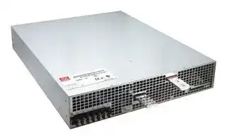
RST-10000-24
AC/DC Enclosed Power Supply (PSU), ITE, 1 Outputs, 9.6 kW, 24 VDC, 400 A
⚠️ Reference pricing provided. In case of supply shortages, we will connect you with our trusted procurement partners to ensure your project's continuity.
- Manufacturer: MEAN WELL
- Product type: AC / DC Enclosed Power Supplies
- No. of Outputs:1Outputs; Output Power Max:9.6kW; Output Voltage - Output 1:24V; Output Current - Output 1:400A; Output Voltage - Output 2:-; Output Cu; Available until stocks are exhausted
- SVHC: No SVHC (27-Jun-2024)
- Product Range: RST-10000 Series
- No. of Outputs: 1Outputs
- Output Power Max: 9.6kW
- Input Voltage VAC: 196V AC to 305V AC, 340V AC to 530V AC
- Power Supply Output Type: Adjustable, Fixed
- Output Current - Output 1: 400A
- Output Current - Output 2: -
- Output Current - Output 3: -
- Output Current - Output 4: -
- Output Voltage - Output 1: 24VDC
- Output Voltage - Output 2: -
- Output Voltage - Output 3: -
- Output Voltage - Output 4: -
- Power Supply Applications: ITE
| Delivery and price | |
|---|---|
| Units per pack | 1 |
| Price | 2176.74 € |
| Current stock | 10+ |
| Lead time | 30 days |
Datasheet

> 10000W Power Supply with Single Output **RST- 10000 series**

**==> picture [517 x 312] intentionally omitted <==**

**----- Start of picture text -----**<br>
540 * 424 * 83.5(2U) mm BauarSicherheitbeegelodwacmat geprufto ges g<br>www.ID 2000000000tuv.com<br>21.3 * 16.7 * 3.29(2U) inch Parallel  -Akis L A ) | EAL CB C €<br>■ Features ■ Certificates<br>*3 ψ 3-wire/ △ 196~305VAC or3 ψ 4-wire/ Y 340~530VAC * Safety: UL/EN/IEC 60950-1<br>wide input range * EMC: EN 55022 / 55024<br>* Built-in active PFC function<br>* High efficiency up to 91%<br>* Forced air cooling by built-in DC fan ■ Applications<br>* Output voltage and constant current level programmable - Factory control or automation apparatus<br>* Active current sharing up to 20000W (1+1) * Test and measurement instrument<br>* Built-in remote ON-OFF control / Remote sense * Laser related machine<br>/ Auxilary power / Alarm signal * Burn-in facility<br>* OverProtections:temperatureShort circuit/ Fan fail/ Overload / Over voltage/ -. RF application;<br>5 Electric scooter or vehicle charger<br>years warranty * Constant current source<br>■ Description<br>RST-10000 is a 10KW single output enclosed type AC/DC power supply. This series operates for the wide<br>range three phase AC input (3 phase 3 wire/ △ 196~305VAC or 3 phase 4 wire / Y 340~530VAC) and offers<br>the models with the DC output mostly demanded from the industry. Each model is cooled by the built-in<br>℃<br>**----- End of picture text -----**<br>


**==> picture [13 x 128] intentionally omitted <==**

**----- Start of picture text -----**<br>
■<br>■<br>**----- End of picture text -----**<br>


_File Name:RST-10000-SPEC   2018-01-15_

**RST- 10000 series**

10000W Power Supply with Single Output

## **SPECIFICATION**

|**MODEL**<br>**DC VOLTAGE**<br>**RATED CURRENT**<br>**CURRENT RANGE**<br>**RATED POWER**<br>**OUTPUT**<br>**VOLTAGE ADJ. RANGE**<br>**LINE REGULATION**<br>**LOAD REGULATION**<br>**SETUP, RISE TIME**<br>**HOLD UP TIME (Typ.)**<br>**VOLTAGE RANGE**<br>**FREQUENCY RANGE**<br>**EFFICIENCY (Typ.)**<br>**INPUT**<br>**INRUSH CURRENT (Typ.)**<br>**LEAKAGE CURRENT**<br>**OVER TEMPERATURE**<br>**WORKING TEMP.**<br>**ALARM SIGNAL OUTPUT**<br>**WORKING HUMIDITY**<br>**STORAGE TEMP., HUMIDITY**<br>**TEMP. COEFFICIENT**<br>**VIBRATION**<br>**MTBF**<br>**DIMENSION**<br>**OTHERS**<br>**NOTE**<br>**PACKING**<br>**OVERLOAD(OLP)**<br>**OVER VOLTAGE**<br>**AC CURRENT (Typ.)**<br>2200ms, 80ms at full load<br>20ms / 230VAC at 75% load          14ms / 230VAC at full load<br>3<br>3-wire /<br>196 ~ 305VAC or 3<br>4-wire / Y 340 ~ 530VAC<br>ψ<br>△<br>ψ<br>47 ~ 63Hz<br>30A/230VAC(<br>)         18A/400VAC(<br>/ Y)<br>3<br>3-wire /<br>3<br>4-wire<br>ψ<br>△<br>ψ<br>150A/230VAC(<br>)         100A/400VAC(<br>/ Y)<br>3<br>3-wire /<br>3<br>4-wire<br>ψ<br>△<br>ψ<br><7mA /<br>305VAC(Y 530VAC)<br>△<br>100 ~ 112% rated output power<br>User selectable continuous constant current limiting or constant current limiting with delay shutdown after 5 seconds, re-power on to recover<br>Protection type : Shut down o/p voltage, re-power on to recover<br>-30 ~ +70<br>(Refer to "Derating Curve")<br>℃<br>AC fail, DC OK, fan fail, OTP. Please refer to the Function Manual.<br>20 ~ 90% RH non-condensing<br>-40 ~ +85<br>, 10 ~ 95% RH non-condensing<br>℃<br>±<br>℃<br>℃<br>0.03%/<br>(0 ~ 50<br>)<br>10 ~ 500Hz, 2G 10min./1cycle, 60min. each along X, Y, Z axes<br>50K hrs min.<br>Telcordia SR-332 (Bellcore) ; 17K hrs min.      MIL-HDBK-217F (25<br>)<br>℃<br>540*424*83.5mm (L*W*H)<br>23.5Kg; 1pcs/23.5Kg/2.82CUFT<br>89%<br>91%<br>90%<br>△<br>℃<br>℃<br>℃<br>**POWER FACTOR (Typ.)**<br>0.95/230VAC(400VAC) at full load<br>**SAFETY STANDARDS**<br>UL60950-1, TUV EN60950-1 EAC TP TC 004 approved<br>,<br>**RIPPLE & NOISE (max.) Note.2**<br>**VOLTAGE TOLERANCE Note.3**<br>**WITHSTAND VOLTAGE Note.4**<br>**ISOLATION RESISTANCE Note.4**<br>I/P-O/P:3KVAC     I/P-FG:2KVAC     O/P-FG:0.5KVAC<br>I/P-O/P, I/P-FG, O/P-FG:100M Ohms / 500VDC / 25<br>/ 70% RH<br>℃<br>**ENVIRONMENT**<br>**SAFETY &**<br>**FUNCTION**<br>**EMC**<br>**(Note 6)**<br>**PROTECTION**<br>Shut down o/p voltage, recovers automatically after temperature goes down<br>30 ~ 33.6V<br>60 ~ 67.2V<br>45 ~ 50.4V<br>±0.5%<br>±0.5%<br>±0.5%<br>±0.5%<br>±0.5%<br>±0.5%<br>±1.0%<br>Can be adjusted via built-in potentiometer<br>±1.0%<br>±1.0%<br>150mVp-p<br>23.5 ~ 28.8V<br>200mVp-p<br>200mVp-p<br>47 ~ 57.6V<br>35 ~ 43.2V<br>24V<br>400A<br>0 ~ 400A<br>9600W<br>48V<br>36V<br>210A<br>276A<br>0 ~ 210A<br>0 ~ 276A<br>10080W<br>9936W<br>**RST-10000-24**<br>**RST-10000-48**<br>**RST-10000-36**<br>**REMOTE SENSE**<br>Compensate voltage drop on the load wiring up to 0.3V. Please refer to the Function Manual.<br>**REMOTE ON-OFF CONTROL**<br>**AUXILIARY POWER**<br>**CURRENT SHARING**<br>By electrical signal or dry contact     Power ON:open     Power OFF:short. Please refer to the Function Manual.<br>12V@0.1A(Only for Remote ON/OFF control)<br>Up to 20000W or (1+1) units. Please refer to the Function Manual.<br>**Parameter**<br>**Parameter**<br>ESD<br>Radiated<br>EFT / Burst<br>Surge<br>Conducted<br>Magnetic Field<br>Voltage Dips and Interruptions<br>Conducted<br>Radiated<br>Harmonic Current<br>Voltage Flicker<br>EN55024 , EN61204-3, EN61000-6-2<br>**Standard**<br>**Standard**<br>EN55032 (CISPR32) / EN55011 (CISPR11)<br>EN55032 (CISPR32) / EN55011 (CISPR11)<br>EN61000-3-2<br>EN61000-3-3<br>EN61000-4-2<br>EN61000-4-3<br>EN61000-4-4<br>EN61000-4-5<br>EN61000-4-6<br>EN61000-4-8<br>EN61000-4-11<br>**Test Level / Note**<br>**Test Level / Note**<br>Level 3, 8KV air ; Level 2, 4KV contact<br>Level 3<br>Level 3<br>Level 3<br>Level 4<br>>95% dip 0.5 periods, 30% dip 25 periods,<br>>95% interruptions 250 periods<br>Class A<br>Class A<br>-----<br>-----<br>**EMC IMMUNITY**<br>**EMC EMISSION**<br>**CONSTANT CURRENT LEVEL PROGRAMMABLE**<br>Level 4, 4KV/Line-Earth ; Level 3, 2KV/Line-Line<br>Adjustment of output voltage is allowable to between 20 ~ 120% of nominal output voltage. Please refer to the Function Manual.<br>Adjustment of constant current level is allowable to between 20 ~ 100% of rated current. Please refer to the Function Manual.<br>**OUTPUT VOLTAGE PROGRAMMABLE**<br>~~=~~<br>1. All parameters NOT specially mentioned are measured at<br>230VAC(Y 400VAC) input, rated load and 25<br>of ambient temperature.<br>2. Ripple & noise are measured at20MHz of bandwidth by using a 12" twisted pair-wire terminated with a 0.1uf & 47uf parallel capacitor.<br>3. Tolerance: includes set up tolerance, line regulation and load regulation.<br>4. During withstand voltage and isolation resistance testing, the screw “A” shall be temporarily removed, and shall be installed back after the testing.<br>5. There is high possibility to trigger the floating over voltage protection when PV voltage istrimmed froma high voltage level to a lower voltage level at light<br>load or no load condition. It is suggested that turn off the power supply and set PV voltage to the lowest level, then adjust output voltage to a desired value.<br>6. The power supply is considered a component which will be installed into a final equipment. All the EMC tests are been executed by mounting the unit on<br>a 1300mm*900mm metal plate with 2mm of thickness. The final equipment must be re-confirmed that it still meets EMC directives. For guidance on how to<br>perform these EMC tests, please refer to “EMI testing of component power supplies.” (as available on http:/Wwww.meanwell.com)<br>7. The ambient temperature derating of 3.5<br>/1000m with fanless models and of<br>5<br>/1000m with fan models for operating altitude higher than 2000m(6500ft).|**MODEL**<br>**DC VOLTAGE**<br>**RATED CURRENT**<br>**CURRENT RANGE**<br>**RATED POWER**<br>**OUTPUT**<br>**VOLTAGE ADJ. RANGE**<br>**LINE REGULATION**<br>**LOAD REGULATION**<br>**SETUP, RISE TIME**<br>**HOLD UP TIME (Typ.)**<br>**VOLTAGE RANGE**<br>**FREQUENCY RANGE**<br>**EFFICIENCY (Typ.)**<br>**INPUT**<br>**INRUSH CURRENT (Typ.)**<br>**LEAKAGE CURRENT**<br>**OVER TEMPERATURE**<br>**WORKING TEMP.**<br>**ALARM SIGNAL OUTPUT**<br>**WORKING HUMIDITY**<br>**STORAGE TEMP., HUMIDITY**<br>**TEMP. COEFFICIENT**<br>**VIBRATION**<br>**MTBF**<br>**DIMENSION**<br>**OTHERS**<br>**NOTE**<br>**PACKING**<br>**OVERLOAD(OLP)**<br>**OVER VOLTAGE**<br>**AC CURRENT (Typ.)**<br>2200ms, 80ms at full load<br>20ms / 230VAC at 75% load          14ms / 230VAC at full load<br>3<br>3-wire /<br>196 ~ 305VAC or 3<br>4-wire / Y 340 ~ 530VAC<br>ψ<br>△<br>ψ<br>47 ~ 63Hz<br>30A/230VAC(<br>)         18A/400VAC(<br>/ Y)<br>3<br>3-wire /<br>3<br>4-wire<br>ψ<br>△<br>ψ<br>150A/230VAC(<br>)         100A/400VAC(<br>/ Y)<br>3<br>3-wire /<br>3<br>4-wire<br>ψ<br>△<br>ψ<br><7mA /<br>305VAC(Y 530VAC)<br>△<br>100 ~ 112% rated output power<br>User selectable continuous constant current limiting or constant current limiting with delay shutdown after 5 seconds, re-power on to recover<br>Protection type : Shut down o/p voltage, re-power on to recover<br>-30 ~ +70<br>(Refer to "Derating Curve")<br>℃<br>AC fail, DC OK, fan fail, OTP. Please refer to the Function Manual.<br>20 ~ 90% RH non-condensing<br>-40 ~ +85<br>, 10 ~ 95% RH non-condensing<br>℃<br>±<br>℃<br>℃<br>0.03%/<br>(0 ~ 50<br>)<br>10 ~ 500Hz, 2G 10min./1cycle, 60min. each along X, Y, Z axes<br>50K hrs min.<br>Telcordia SR-332 (Bellcore) ; 17K hrs min.      MIL-HDBK-217F (25<br>)<br>℃<br>540*424*83.5mm (L*W*H)<br>23.5Kg; 1pcs/23.5Kg/2.82CUFT<br>89%<br>91%<br>90%<br>△<br>℃<br>℃<br>℃<br>**POWER FACTOR (Typ.)**<br>0.95/230VAC(400VAC) at full load<br>**SAFETY STANDARDS**<br>UL60950-1, TUV EN60950-1 EAC TP TC 004 approved<br>,<br>**RIPPLE & NOISE (max.) Note.2**<br>**VOLTAGE TOLERANCE Note.3**<br>**WITHSTAND VOLTAGE Note.4**<br>**ISOLATION RESISTANCE Note.4**<br>I/P-O/P:3KVAC     I/P-FG:2KVAC     O/P-FG:0.5KVAC<br>I/P-O/P, I/P-FG, O/P-FG:100M Ohms / 500VDC / 25<br>/ 70% RH<br>℃<br>**ENVIRONMENT**<br>**SAFETY &**<br>**FUNCTION**<br>**EMC**<br>**(Note 6)**<br>**PROTECTION**<br>Shut down o/p voltage, recovers automatically after temperature goes down<br>30 ~ 33.6V<br>60 ~ 67.2V<br>45 ~ 50.4V<br>±0.5%<br>±0.5%<br>±0.5%<br>±0.5%<br>±0.5%<br>±0.5%<br>±1.0%<br>Can be adjusted via built-in potentiometer<br>±1.0%<br>±1.0%<br>150mVp-p<br>23.5 ~ 28.8V<br>200mVp-p<br>200mVp-p<br>47 ~ 57.6V<br>35 ~ 43.2V<br>24V<br>400A<br>0 ~ 400A<br>9600W<br>48V<br>36V<br>210A<br>276A<br>0 ~ 210A<br>0 ~ 276A<br>10080W<br>9936W<br>**RST-10000-24**<br>**RST-10000-48**<br>**RST-10000-36**<br>**REMOTE SENSE**<br>Compensate voltage drop on the load wiring up to 0.3V. Please refer to the Function Manual.<br>**REMOTE ON-OFF CONTROL**<br>**AUXILIARY POWER**<br>**CURRENT SHARING**<br>By electrical signal or dry contact     Power ON:open     Power OFF:short. Please refer to the Function Manual.<br>12V@0.1A(Only for Remote ON/OFF control)<br>Up to 20000W or (1+1) units. Please refer to the Function Manual.<br>**Parameter**<br>**Parameter**<br>ESD<br>Radiated<br>EFT / Burst<br>Surge<br>Conducted<br>Magnetic Field<br>Voltage Dips and Interruptions<br>Conducted<br>Radiated<br>Harmonic Current<br>Voltage Flicker<br>EN55024 , EN61204-3, EN61000-6-2<br>**Standard**<br>**Standard**<br>EN55032 (CISPR32) / EN55011 (CISPR11)<br>EN55032 (CISPR32) / EN55011 (CISPR11)<br>EN61000-3-2<br>EN61000-3-3<br>EN61000-4-2<br>EN61000-4-3<br>EN61000-4-4<br>EN61000-4-5<br>EN61000-4-6<br>EN61000-4-8<br>EN61000-4-11<br>**Test Level / Note**<br>**Test Level / Note**<br>Level 3, 8KV air ; Level 2, 4KV contact<br>Level 3<br>Level 3<br>Level 3<br>Level 4<br>>95% dip 0.5 periods, 30% dip 25 periods,<br>>95% interruptions 250 periods<br>Class A<br>Class A<br>-----<br>-----<br>**EMC IMMUNITY**<br>**EMC EMISSION**<br>**CONSTANT CURRENT LEVEL PROGRAMMABLE**<br>Level 4, 4KV/Line-Earth ; Level 3, 2KV/Line-Line<br>Adjustment of output voltage is allowable to between 20 ~ 120% of nominal output voltage. Please refer to the Function Manual.<br>Adjustment of constant current level is allowable to between 20 ~ 100% of rated current. Please refer to the Function Manual.<br>**OUTPUT VOLTAGE PROGRAMMABLE**<br>~~=~~<br>1. All parameters NOT specially mentioned are measured at<br>230VAC(Y 400VAC) input, rated load and 25<br>of ambient temperature.<br>2. Ripple & noise are measured at20MHz of bandwidth by using a 12" twisted pair-wire terminated with a 0.1uf & 47uf parallel capacitor.<br>3. Tolerance: includes set up tolerance, line regulation and load regulation.<br>4. During withstand voltage and isolation resistance testing, the screw “A” shall be temporarily removed, and shall be installed back after the testing.<br>5. There is high possibility to trigger the floating over voltage protection when PV voltage istrimmed froma high voltage level to a lower voltage level at light<br>load or no load condition. It is suggested that turn off the power supply and set PV voltage to the lowest level, then adjust output voltage to a desired value.<br>6. The power supply is considered a component which will be installed into a final equipment. All the EMC tests are been executed by mounting the unit on<br>a 1300mm*900mm metal plate with 2mm of thickness. The final equipment must be re-confirmed that it still meets EMC directives. For guidance on how to<br>perform these EMC tests, please refer to “EMI testing of component power supplies.” (as available on http:/Wwww.meanwell.com)<br>7. The ambient temperature derating of 3.5<br>/1000m with fanless models and of<br>5<br>/1000m with fan models for operating altitude higher than 2000m(6500ft).|**RST-10000-24**|**RST-10000-36**|**RST-10000-48**|
|---|---|---|---|---|
||**DC VOLTAGE**|24V|36V|48V|
||**RATED CURRENT**|400A|276A|210A|
||**CURRENT RANGE**|0 ~ 400A|0 ~ 276A|0 ~ 210A|
||**RATED POWER**|9600W|9936W|10080W|
||**RIPPLE & NOISE (max.) Note.2**|150mVp-p|200mVp-p|200mVp-p|
||**VOLTAGE ADJ. RANGE**|Can be adjusted via built-in potentiometer<br>23.5 ~ 28.8V<br>47 ~ 57.6V<br>35 ~ 43.2V|||
||**VOLTAGE TOLERANCE Note.3**|±1.0%|±1.0%|±1.0%|
||**LINE REGULATION**|±0.5%|±0.5%|±0.5%|
||**LOAD REGULATION**|±0.5%|±0.5%|±0.5%|
||**SETUP, RISE TIME**|2200ms, 80ms at full load|||
||**HOLD UP TIME (Typ.)**|20ms / 230VAC at 75% load          14ms / 230VAC at full load|||
||**VOLTAGE RANGE**|3<br>3-wire /<br>196 ~ 305VAC or 3<br>4-wire / Y 340 ~ 530VAC<br>ψ<br>△<br>ψ|||
||**FREQUENCY RANGE**|47 ~ 63Hz|||
||**POWER FACTOR (Typ.)**|0.95/230VAC(400VAC) at full load|||
||**EFFICIENCY (Typ.)**|89%|90%|91%|
||**AC CURRENT (Typ.)**|30A/230VAC(<br>)         18A/400VAC(<br>/ Y)<br>3<br>3-wire /<br>3<br>4-wire<br>ψ<br>△<br>ψ|||
||**INRUSH CURRENT (Typ.)**|150A/230VAC(<br>)         100A/400VAC(<br>/ Y)<br>3<br>3-wire /<br>3<br>4-wire<br>ψ<br>△<br>ψ|||
||**LEAKAGE CURRENT**<br>~~=~~|<7mA /<br>305VAC(Y 530VAC)<br>△|||
||**OVERLOAD(OLP)**<br>~~=~~|100 ~ 112% rated output power<br>User selectable continuous constant current limiting or constant current limiting with delay shutdown after 5 seconds, re-power on to recover|||
||**OVER VOLTAGE**<br>~~=~~|Protection type : Shut down o/p voltage, re-power on to recover<br>30 ~ 33.6V<br>60 ~ 67.2V<br>45 ~ 50.4V|||
||**OVER TEMPERATURE**<br>~~=~~|Shut down o/p voltage, recovers automatically after temperature goes down|||
||**REMOTE SENSE**<br>~~=~~|Compensate voltage drop on the load wiring up to 0.3V. Please refer to the Function Manual.|||
||**CURRENT SHARING**|Up to 20000W or (1+1) units. Please refer to the Function Manual.|||
||**AUXILIARY POWER**|12V@0.1A(Only for Remote ON/OFF control)|||
||**REMOTE ON-OFF CONTROL**|By electrical signal or dry contact     Power ON:open     Power OFF:short. Please refer to the Function Manual.|||
||**OUTPUT VOLTAGE PROGRAMMABLE**|Adjustment of output voltage is allowable to between 20 ~ 120% of nominal output voltage. Please refer to the Function Manual.|||
||**CONSTANT CURRENT LEVEL PROGRAMMABLE**|Adjustment of constant current level is allowable to between 20 ~ 100% of rated current. Please refer to the Function Manual.|||
||**ALARM SIGNAL OUTPUT**|AC fail, DC OK, fan fail, OTP. Please refer to the Function Manual.|||
||**WORKING TEMP.**|-30 ~ +70<br>(Refer to "Derating Curve")<br>℃|||
||**WORKING HUMIDITY**|20 ~ 90% RH non-condensing|||
||**STORAGE TEMP., HUMIDITY**|-40 ~ +85<br>, 10 ~ 95% RH non-condensing<br>℃|||
||**TEMP. COEFFICIENT**|±<br>℃<br>℃<br>0.03%/<br>(0 ~ 50<br>)|||
||**VIBRATION**|10 ~ 500Hz, 2G 10min./1cycle, 60min. each along X, Y, Z axes|||
||**SAFETY STANDARDS**|UL60950-1, TUV EN60950-1 EAC TP TC 004 approved<br>,|||
||**WITHSTAND VOLTAGE Note.4**|I/P-O/P:3KVAC     I/P-FG:2KVAC     O/P-FG:0.5KVAC|||
||**ISOLATION RESISTANCE Note.4**<br>**EMC IMMUNITY**<br>**EMC EMISSION**|I/P-O/P, I/P-FG, O/P-FG:100M Ohms / 500VDC / 25<br>/ 70% RH<br>℃|||
|||**Parameter**|**Standard**|**Test Level / Note**|
|||Conducted|EN55032 (CISPR32) / EN55011 (CISPR11)|Class A|
|||Radiated|EN55032 (CISPR32) / EN55011 (CISPR11)|Class A|
|||Harmonic Current|EN61000-3-2|-----|
|||Voltage Flicker|EN61000-3-3|-----|
|||EN55024 , EN61204-3, EN61000-6-2|||
|||**Parameter**|**Standard**|**Test Level / Note**|
|||ESD|EN61000-4-2|Level 3, 8KV air ; Level 2, 4KV contact|
|||Radiated|EN61000-4-3|Level 3|
|||EFT / Burst|EN61000-4-4|Level 3|
|||Surge|EN61000-4-5|Level 4, 4KV/Line-Earth ; Level 3, 2KV/Line-Line|
|||Conducted|EN61000-4-6|Level 3|
|||Magnetic Field|EN61000-4-8|Level 4|
|||Voltage Dips and Interruptions|EN61000-4-11|>95% dip 0.5 periods, 30% dip 25 periods,<br>>95% interruptions 250 periods|
||**MTBF**|50K hrs min.<br>Telcordia SR-332 (Bellcore) ; 17K hrs min.      MIL-HDBK-217F (25<br>)<br>℃|||
||**DIMENSION**|540*424*83.5mm (L*W*H)|||
||**PACKING**|23.5Kg; 1pcs/23.5Kg/2.82CUFT|||
||△<br>℃<br>℃<br>℃<br>1. All parameters NOT specially mentioned are measured at<br>230VAC(Y 400VAC) input, rated load and 25<br>of ambient temperature.<br>2. Ripple & noise are measured at20MHz of bandwidth by using a 12" twisted pair-wire terminated with a 0.1uf & 47uf parallel capacitor.<br>3. Tolerance: includes set up tolerance, line regulation and load regulation.<br>4. During withstand voltage and isolation resistance testing, the screw “A” shall be temporarily removed, and shall be installed back after the testing.<br>5. There is high possibility to trigger the floating over voltage protection when PV voltage istrimmed froma high voltage level to a lower voltage level at light<br>load or no load condition. It is suggested that turn off the power supply and set PV voltage to the lowest level, then adjust output voltage to a desired value.<br>6. The power supply is considered a component which will be installed into a final equipment. All the EMC tests are been executed by mounting the unit on<br>a 1300mm*900mm metal plate with 2mm of thickness. The final equipment must be re-confirmed that it still meets EMC directives. For guidance on how to<br>perform these EMC tests, please refer to “EMI testing of component power supplies.” (as available on http:/Wwww.meanwell.com)<br>7. The ambient temperature derating of 3.5<br>/1000m with fanless models and of<br>5<br>/1000m with fan models for operating altitude higher than 2000m(6500ft).||||


℃ /1000m with fanless models and of 5 ℃ /1000m with fan models for operating altitude higher than 2000m(6500ft). _File Name:RST-10000-SPEC   2018-01-15_

**RST- 10000 series**

## 10000W Power Supply with Single Output

**==> picture [511 x 668] intentionally omitted <==**

**----- Start of picture text -----**<br>
Block Diagram<br>PFC fosc : 70KHz<br>PWM fosc : 100KHz<br>+S<br>EMI RECTIFIERS POWER RECTIFIERS +V<br>I/P FILTER & SWITCHING & -V<br>PFC FILTER<br>-S<br>O.T.P. DETECTION<br>PFC CIRCUIT<br>FG<br>CONTROL<br>CONTROL CURRENT<br>CIRCUIT LIMIT<br>O.V.P.<br>CS<br>PV<br>PC<br>Remote ON-OFF<br>ISOLATOR DC-OK<br>& AC-FAIL<br>RELAY FAN-FAIL<br>OTP<br>AUX RECTIFIERS AUX POWER<br>&<br>POWER FILTER (+12V/0.1A)<br>FAN<br>Derating Curve<br>100<br>80 MODEL 24V 36V 48V<br>INPUT<br>60 △196~305VAC 9600W 9936W 10080W<br>340~530VAC 400A 276A 210A<br>50<br>40<br>20<br>-30 0 10 20 30 40 50 60 70 (HORIZONTAL)<br>AMBIENT TEMPERATURE ( ℃ )<br>Static Characteristics Efficiency vs Load (48V Model)<br>92<br>90<br>100 88<br>90 86<br>80 84 400V(Y)<br>70 82<br>230V(△? )<br>60 80<br>50 78<br>10% 20% 30% 40% 50% 60% 70% 80% 90% 100%<br>3ψ△ 196 210 220 230 240 250 260 270 280 290 305<br>3ψY 340 360 380 400 420 440 460 480 500 515 530 LOAD 91.07%/230VAC (△)<br>INPUT VOLTAGE (V) 60Hz 91.26%/400VAC(Y)<br>LOAD (%)<br>EFFICIENCY (%)<br>LOAD (%)<br>**----- End of picture text -----**<br>


_File Name:RST-10000-SPEC   2018-01-15_

**RST- 10000 series**

10000W Power Supply with Single Output

## **AC Power Connection**

**==> picture [348 x 293] intentionally omitted <==**

**----- Start of picture text -----**<br>
◎ψ3 3 wire / △ 230VAC T RST-10000<br>N3<br>L3<br>N2<br>L2<br>N1<br>L1<br>S<br>R FG<br>Fig 1.1<br>◎ψ3 4 wire / Y 400VAC<br>T RST-10000<br>N3<br>L3<br>N2<br>N L2<br>N1<br>L1<br>S<br>R FG<br>Fig 1.2<br>230V<br>230V<br>230V<br>400V<br>**----- End of picture text -----**<br>


## **Function Manual**

## **1.Remote Sense**

- ※ The remote sense function compensates the voltage drop on the cable, between the power supply and the load, up to 0.3V.

- ※ If the remote sense function is not required,+S and +V of the output terminal, as well as -S and -V, need to be connected to be free from noise and interference. (+S and +V of the output terminal, -S and -V are connected as factory default setting)

**==> picture [384 x 144] intentionally omitted <==**

**----- Start of picture text -----**<br>
+V<br>DIPSW CN993 CN992 CN991 SVR<br>-V<br>PIN3 +S<br>+V<br>LOAD<br>PIN5 -S<br>-V<br>Sense lines should be twisted in pairs to minimize<br>noise pick-up.<br>Fig 1.1<br>**----- End of picture text -----**<br>


_File Name:RST-10000-SPEC   2018-01-15_

**RST- 10000 series**

## 10000W Power Supply with Single Output

## **2.Voltage Adjustment**

**==> picture [173 x 53] intentionally omitted <==**

**----- Start of picture text -----**<br>
(1)by potentiometer (SVR) ON 1 2 3<br>(a)Have the DIP switch position-3 set as OFF<br>(b)Output voltage can be trimmed by SVR.<br>(2)by Output Voltage Programming* ON 1 2 3<br>(a)Have the DIP switch position-3 set as OFF<br>**----- End of picture text -----**<br>


- (b)The output voltage can be trimmed to 20~120% of the nominal voltage by applying EXTERNAL VOLTAGE between _PV_ + and _PV-_ on CN992 or CN993.

**==> picture [385 x 145] intentionally omitted <==**

**----- Start of picture text -----**<br>
+V<br>DIPSW CN993 CN992 CN991 SVR SVR<br>-V<br>CN993<br>DIP +V<br>SWITCH<br>LOAD<br>-V<br>PIN4 PV- PIN6 PV+<br>EXTERNAL VOLTAGE (DC)<br>Fig 2.1<br>**----- End of picture text -----**<br>


◎+S and +V, as well as -S and -V, need to be connected as factory default setting

**==> picture [183 x 182] intentionally omitted <==**

**----- Start of picture text -----**<br>
Nominal Vout<br>120<br>100<br>80<br>Non-Linear<br>60<br>40<br>20<br>V<br>1 2 3 4 5 6<br>EXTERNAL VOLTAGE (VDC)<br>Fig 2.2<br>OUTPUT VOLTAGE (%)<br>**----- End of picture text -----**<br>


*: or, PV/remote voltage programming / remote adjust / margin programming / dynamic voltage trim.

_File Name:RST-10000-SPEC   2018-01-15_

**RST- 10000 series**

## 10000W Power Supply with Single Output

## **3.Current Adjustment**

**==> picture [172 x 55] intentionally omitted <==**

**----- Start of picture text -----**<br>
(1)Default Overload Protection(OLP) value ON 1 2 3<br>(a)Have the DIP switch position-2 set as OFF<br>(b)Output current is set default value.<br>(2)by Constant Current Level Programming**ON 1 2 3<br>(a)Have the DIP switch position-2 set as OFF<br>**----- End of picture text -----**<br>


- (b)The constant current level can be trimmed to 20~100% of the rated current by applying EXTERNAL VOLTAGE between _PC+_ and _PC-_ on CN992 or CN993.

**==> picture [385 x 145] intentionally omitted <==**

**----- Start of picture text -----**<br>
+V<br>DIPSW CN993 CN992 CN991 SVR<br>-V<br>CN993<br>+V<br>LOAD<br>-V<br>PIN7 PC- PIN9 PC+<br>EXTERNAL VOLTAGE (DC)<br>Fig 3.1<br>**----- End of picture text -----**<br>


**==> picture [286 x 241] intentionally omitted <==**

**----- Start of picture text -----**<br>
◎+S and +V, as well as -S and -V, need to be connected as factory default setting<br>Rated Current<br>100<br>80<br>Non-Linear<br>60<br>40<br>20<br>V<br>1 2 3 4 5<br>EXTERNAL VOLTAGE (VDC)<br>Fig 3.2<br>CONSTANT CURRENT LEVEL (%)<br>**----- End of picture text -----**<br>


**: or, PC/remote current programming / dynamic current trim.

_File Name:RST-10000-SPEC   2018-01-15_

**RST- 10000 series**

10000W Power Supply with Single Output

## **4.Select Overload Protection (OLP) Mode**

- (1)Continuous Constant Current mode

- 1 2 3

- ON

- Have the DIP switch position-1 set as                   ,and RST-10000 will work in continuous constant current mode when the output is overloaded andOFF the output voltage is greater than 50% of the rated output voltage.

- (2)Delay Shutdown mode

- 1 2 3

- ON

- Have the DIP switch position-1 set as                   ,and RST-10000 will shut down after 5 seconds of constant current operation, when the output isOFF overloaded or short-circuited.

## **5.Remote ON-OFF Control**

- ※ The power supply can be turned ON-OFF by using the "Remote ON-OFF" function.

**==> picture [465 x 236] intentionally omitted <==**

**----- Start of picture text -----**<br>
Between Remote ON-OFF ( CN992 or CN993 pin10 ) and 12V-AUX( CN991 pin1 ) Output Status<br>Switch close (Short) power supply ON<br>Switch open (Open) power supply OFF<br>Table 5.1<br>SW<br>12V-AUX<br>+V RST-10000 RC+<br>RC-<br>GND-AUX<br>DIPSW CN993 CN992 CN991 SVR<br>-V<br>PIN1 12V-AUX<br>CN993 PIN3 GND-AUX<br>PIN8 RC- PIN10 RC+ CN991<br>Fig 5.1<br>**----- End of picture text -----**<br>


## **6.Alarm Signal Output**

- ※ There are 4 alarm signals on CN991, and each signal can select two types of output circuit.

- (1)Relay contact output {OTP1, OTP1-GND) ; (DC-OK1, DC-OK1-GND) ; (AC-FAIL1-GND, AC-FAIL1) ; (FAN-FAIL1-GND, FAN-FAIL1)} Normally open contact. "Short" when the alarm arises. Relay contact rating(maximum) is 30V/1A resistive.

**==> picture [84 x 76] intentionally omitted <==**

**----- Start of picture text -----**<br>
R<br>V<br>Fig 6.1<br>**----- End of picture text -----**<br>


- (2)Open collector output {DC-OK2-GND, DC-OK2) ; (AC-FAIL2-GND, AC-FAIL2) ; (OTP2, OTP2-GND) ; (FAN-FAIL2, FAN-FAIL2-GND)} An external voltage source is required for this function that is shown in Fig 6.2. These signals are isolated from output. The maximum sink current is 10mA and the maximum external voltage is 20V (there is a built-in 24V zener diode in inner circuitry).

**==> picture [332 x 155] intentionally omitted <==**

**----- Start of picture text -----**<br>
12V-AUX 10KΩ x4pcs<br>DC-OK2<br>DC-OK2-GND<br>AC-FAIL2<br>RST-10000 AC-FAIL2-GND<br>Application<br>OTP2<br>Circuit<br>OTP2-GND<br>FAN-FAIL2<br>FAN-FAIL2-GND<br>GND-AUX<br>**----- End of picture text -----**<br>


Fig 6.2

_File Name:RST-10000-SPEC   2018-01-15_

**RST- 10000 series**

10000W Power Supply with Single Output

## **7.Current Sharing**

RST-10000 has the built-in active current sharing function and can be connected in parallel, up to 2 units, to provide higher output power as exhibited below :

- ※ The voltage difference among each output should be minimized that less than 0.2V is required.

- ※ The total output current must not exceed the value determined by the following equation. Maximum output current at parallel operation=(The rated current per unit)x(Number of unit)x0.9

- ※ When the total output current is less than 5% of the total rated current, or say (5% of Rated current per unit)×(Number of unit) the current shared among units may not be fully balanced.

**==> picture [329 x 296] intentionally omitted <==**

**----- Start of picture text -----**<br>
+V<br>DIP CN993 CN992 CN991<br>SW<br>-V<br>+S<br>+V<br>Load<br>-V<br>-S<br>+V<br>DIP CN993 CN992 CN991<br>SW<br>-V<br>**----- End of picture text -----**<br>


- +S,-S and CS+, CS- and RC+, RC- are connected mutually in parallel.

- When the remote sense function is used in parallel operation, the sensing wire must be connected only to the master unit.

- ◎ Wires of the remote sense function should be kept at least 30 cm from input wires.

_File Name:RST-10000-SPEC   2018-01-15_

## 10000W Power Supply with Single Output

## **RST- 10000 series**

**==> picture [506 x 524] intentionally omitted <==**

**----- Start of picture text -----**<br>
Mechanical Specification Case No.234A Unit:mm<br>540<br>488 21<br>1 CN993 CN992 CN991<br>1 1 3 5 7 9 1 3 5 7 9 1 3 5 7 9 11 13 15 17 19<br>2 4 6 8 10 2 4 6 8 10 2 4 6 8 10 12 14 16 18 20<br>4-M4 L=5mm 1<br>68.75 7.4 SVR LED2 LED1<br>406 102.9<br>+<br>8-M4 L=5mm<br>1 1<br>60<br>+V<br>1 1<br>Air flow 2-M3<br>direction<br>-V<br>1 1<br>TB1<br>1<br>2<br>3<br>4<br>5<br>1 1 6<br>22max<br>7 7.1<br>540<br>488 21<br>1<br>1<br>4-M4 L=5mm Screw "A" 1<br>※ Mounting Instruction Chassis of RST-10000<br>Hole No. Recommended Screw Size MAX. Penetration Depth  L Recommended mounting torque Mounting Surface<br>1 M4 5mm 7~1  K0 gf-cm<br>※ Control Pin No. Assignment (CN992,CN993) : HRS DF11-10DP-2DS or equivalent<br>Mounting Screw<br>1 9<br>L<br>Mating Housing HRS DF11-10DS or equivalent<br>Terminal HRS DF11-**SC or equivalent<br>2 10<br>2<br>-ψ<br>8.5<br>DIP-SW<br>10.2<br>CN991<br>10<br>13<br>38 83.5<br>38<br>45.5 45.5<br>120 120<br>30<br>483.6 466.1 91.6 91.6 424<br>120 120<br>22.7<br>22.7<br>+<br>SVRLED1LED2<br>CN992<br>CN993ON 321<br>**----- End of picture text -----**<br>


- CN992 and CN993 are connected internally.

## **Pin No. Function Description**

|**Pin No. **|**Function **|**Description**|
|---|---|---|
|1|CS-|Current sharing signal. When units are connected in parallel, the CS pins of the units should be connected to allow current bala<br>between units.|
|2|CS+||
|3|+S|Positive sensing for remote sense.|
|4|PV-|Connection for output voltage<br>.<br>programming|
|6|PV+||
|5|-S|Negative sensing for remote sense.|
|7|PC-|Connection for output current programming.|
|9|PC+||
|8|RC-|The output can be turned ON-OFF in association with RC+ and RC-.|
|10|RC+||


_File Name:RST-10000-SPEC   2018-01-15_

**RST- 10000 series**

10000W Power Supply with Single Output

**==> picture [511 x 668] intentionally omitted <==**

**----- Start of picture text -----**<br>
※ Control Pin No. Assignment (CN991) : HRS DF11-20DP-2DS or equivalent<br>1 19<br>Mating Housing HRS DF11-20DS or equivalent<br>Terminal HRS DF11-**SC or equivalent<br>2 20<br>Pin No. Function Description<br>1 12V-AUX Auxiliary voltage output, 11.4~12.6V, referenced to pin 3(GND-AUX).<br>The maximum load current is 0.1A. This output is not controlled by the "Remote ON/OFF" function.<br>2 DC-OK2-GND Alarm signal of DC-OK.<br>Open collector signal. Low when the PSU turns on. The maximum sink current is 10mA and the maximum external voltage is 20V.<br>4 DC-OK2<br>3 GND-AUX Auxiliary voltage output GND.<br>The signal return is isolated from the output terminals (+V & -V).<br>5 +V(signal) Positive output voltage. For local sense only ; it cannot be connected directly to the load.<br>6 AC-FAIL2-GND Alarm signal of AC fail.<br>Open collector signal. Low when the PSU input voltage is too low. The maximum sink current is 10mA and the maximum external<br>8 AC-FAIL2 voltage is 20V.<br>7 -V(signal) Negative output voltage. For local sense only ; it cannot be connected directly to the load.<br>9 OTP2 Alarm signal of OTP.<br>Open collector signal. Low when the PSU over temperature protection occurs. The maximum sink current is 10mA and the maximum<br>11 OTP2-GND external voltage is 20V.<br>10 FAN-FAIL2<br>Alarm signal of fan fail.<br>12 FAN-FAIL2-GND Open collector signal. Low when the internal fan fails. The maximum sink current is 10mA and the maximum external voltage is 20V.<br>13 OTP1 Alarm signal of OTP.<br>Normally open contact. "Short" when the PSU over temperature protection occurs. Relay contact rating(maximum) is 30V/1A<br>15 OTP1-GND resistive.<br>14 DC-OK1 Alarm signal of DC-OK.<br>16 DC-OK1-GND Normally open contact. "Short" when the PSU turns on. Relay contact rating(maximum) is 30V/1A resistive.<br>17 AC-FAIL1-GND Alarm signal of AC-fail.<br>19 AC-FAIL1 Normally open contact. "Short" when the PSU input voltage is too low. Relay contact rating(maximum) is 30V/1A resistive.<br>18 FAN-FAIL1-GND Alarm signal of fan fail.<br>20 FAN-FAIL1 Normally open contact. "Short" when the internal fan fails. Relay contact rating(maximum) is 30V/1A resistive.<br>※LED Status Indicators<br>LED Description<br>Green(LED1) LED on when output voltage is OK<br>Red(LED2) LED on when any protection occurs<br>※AC Input Terminal Pin No. Assignment (TB1)<br>Pin No. Assignment Pin No. Assignment Diagram Maximum mounting torque<br>1 AC/L1 4 AC/N2<br>2 AC/N1 5 AC/L3 18Kgf-cm<br>3 AC/L2 6 AC/N3<br>※DIP Switch Position Assignment(DIP-SW): Please refer to the Function Manual.<br>Pin No. Assignment Diagram<br>1 Overload Protection (OLP) 1 2 3<br>2 Output Current Programming (PC) OFFON DIP-SW PIN2:PCDIP-SW PIN3:PV<br>3 Output Voltage Programming (PV)<br>Installation Manual<br>Please refer to : http://www.meanwell.com/manual.html<br>**----- End of picture text -----**<br>


_File Name:RST-10000-SPEC   2018-01-15_
Updated at June 6, 2026
About Novapart
Novapart is a B2B electronic component broker specialising in stock shortages and cost reduction. We source hard-to-find parts and identify compliant alternatives across a catalogue of 410,000+ components from 500+ manufacturers.
Learn more →Stock Shortage Specialist
When a component is unavailable, discontinued or has an unacceptable lead time, we tap into our network of vetted European and Asian distributors to source what you need — without compromising on quality or traceability.
Request a quote →Compliant Alternatives
We identify pin-to-pin, electrically equivalent substitutes that meet the same certifications (RoHS, AEC-Q100, REACH) as your original specification — validated against datasheets, not just part numbers. Often at a lower cost.
BOM Analysis service →