
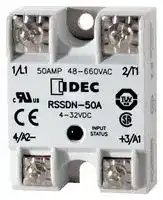


RSSDN-50A
Solid State Relay, SPST-NO, 50 A, 660 VAC, Panel Mount, Screw, Zero Crossing
- Manufacturer: IDEC
- Product type:
- SVHC: No SVHC (25-Jun-2025)
- Load Current: 50A
- Product Range: RSS Series
- Relay Mounting: Panel Mount
- Switching Mode: Zero Crossing
- Relay Terminals: Screw
- Control Voltage Max: 32VDC
- Control Voltage Min: 4VDC
- Contact Configuration: SPST-NO
- Operating Voltage Max: 660VAC
- Operating Voltage Min: 48VAC
| Delivery and price | |
|---|---|
| Units per pack | 10 |
| Price | 35.4 € |
| Current stock | 10+ |
| Lead time | 30 days |
**Relays & Sockets**

**RSS**

## **RSS Series Panel Mount Solid State Relays**

## **Key features:**

- Input status LED Indicator

- Dual SCR output

- Direct bond copper substrate

- Internal transient protection – built-in snubber

- EMC compliant (level 3)

- Photo isolation

- 1200 Volt blocking voltage

- 4000 Volt optical isolation

- Zero voltage turn-on

- High surge capability

- Optional fingersafe terminal cover (RSS-CVR)

UL Recognized File No. E194577

## **Specifications**

## **Part Number Selection**

Continuous Input Part Number Output Current ~~EE~~ 10A RSSAN-10A 25A RSSAN-25A AC Input 90-280V AC 50A RSSAN-50A 75A RSSAN-75A 90A RSSAN-90A ~~im~~ 10A RSSDN-10A 25A RSSDN-25A DC Input ~~2~~ 4-32V DC 50A RSSDN-50A 75A RSSDN-75A ~~——_~~ f 90A RSSDN-90A

|~~EE~~|Series|RSSDN<br>~~eee~~|RSSAN<br>~~eee~~|
|---|---|---|---|
|Input Specifications<br>~~EE~~<br>_—®<br>f|Voltage Range<br>Input Current<br>Pick Up Voltage<br>Drop Out Voltage<br>Dielectric Strength<br>(Input-Output-Base)<br>Capacitance (Input to Output)<br>Rev. Voltage Protection<br>_—®|4 to 32V DC<br>90 to 280V AC<br>current regulated (10mA)<br>4V DC<br>90V AC<br>1V DC<br>10V AC<br>4000 RMS (min)<br>4000 RMS (min)<br>8pF<br>8pF<br>Yes (–32VDC)<br>N/A<br>~~eee~~<br>|<br>~~—_—_——_——~~||
|Output Specifications<br>Current (continuous)<br>1-Cycle Surge Current<br>1-Second Surge Current<br>Minimum Holding Current<br>Voltage Drop at Rated Current<br>Voltage Range<br>Output<br>Over Voltage Rating<br>Frequency Range<br>Off-State Leakage at Rated Voltage<br>Turn-On Time<br>Turn-Off Time<br>Zero Voltage Switching<br>Static DV/DT<br>Commutating DV/DT<br>Weight<br>f<br>|<br>|<br>|<br>|<br>|<br>|<br>|<br>|||10A<br>25A<br>50A<br>75A<br>90A<br>150A<br>300A<br>750A<br>1000A<br>1200A<br>30A<br>75A<br>150A<br>225A<br>300A<br>50mA<br>50mA<br>100mA<br>100mA<br>100mA<br>1.6V (maximum)<br>48 - 660V AC<br>Dual SCR (N.O.)<br>1200 PIV<br>47 to 80Hz<br>20mA (maximum)<br>1/2 cycle @ 60Hz<br>1/2 cycle @ 60Hz<br>Yes<br>200V/µsec<br>Snubbed for 0.5 power factor at rated load<br>10g (approx.)<br>~~—_—_——_——~~<br>|<br>|<br>|||


Hipec

**www.IDEC.com**

822

**Relays  & Sockets**

**RSS**

## **Recommended Loads**

## **Transformer Loads**

Transformer loads sometimes result in severe inrush current when the transformer saturates during the first cycle. Use a relay rated for this surge, which has a 1/2 cycle surge current greater than the maximum applied line voltage; the transformer’s primary resistance (approximately 10x rated current).

## **Recommended Loads**

|SSR Rating<br>at 120V AC<br>at 240V AC|
|---|
|10A<br>500VA<br>1KVA<br>25A<br>1KVA<br>2KVA<br>50A<br>2KVA<br>4KVA<br>~~$$~~<br>~~||~~<br>|||


## **Heater Loads**

When using solid state relays for driving heaters where the load is switched on and off rapidly and continuously, severe thermal stress will result. In such cases, use an SSR relay at no more than 75% of the rating.

## **Recommended Loads**

|SSR Rating<br>~~re~~|at 120V AC<br>~~re~~|at 240V AC<br>~~re~~|
|---|---|---|
|10A<br>25A<br>50A<br>~~re~~<br>~~||~~<br>||1KW<br>2KW<br>3KW<br>~~re~~<br>~~||~~<br>|||2KW<br>4KW<br>6KW<br>~~re~~<br>~~||~~<br>|||


## **Solenoid Valves and Contactors**

RSS relays use high-noise immunity circuitry with a built-in snubber to handle the electrical noise generated by inductive loads.

## **Recommended Loads**

|SSR Rating|at 120V AC|at 240V AC|
|---|---|---|
|10A<br>25A<br>50A<br>||900W<br>2,100W<br>3,800W<br>|<br>||1,800W<br>4,200W<br>7,500W<br>||


RSS series relays provide a highly reliable means of switching AC loads when applied properly. Read the technical notes on the following page prior to installing solid state relays.

**800-262-IDEC** (4332) • USA & Canada

823

**Relays & Sockets**

**RSS**

## **UL Motor Load Ratings (HP Ratings)**

|Part Number|120V|240V|480V|
|---|---|---|---|
|10A<br>25A<br>50A<br>75A<br>90A|1/2<br>1/2<br>3/4<br>3/4<br>3/4|3/4<br>3/4<br>1 1/2<br>5<br>5|3/4<br>3/4<br>1 1/2<br>5<br>5|


## **Lamp Loads**

Zero voltage switching is ideal for driving incandescent lamps, since the cold filament will not be subjected to a large inrush current. Using a zero-switched SSR will reduce inrush current and prolong lamp life.

## **Recommended Loads**

|SSR Rating|at 120V AC|at 240V AC|
|---|---|---|
|10A<br>25A<br>50A|1KW<br>2KW<br>3KW|2KW<br>4KW<br>6KW|


## **Internal Circuit Block Diagram**

Hipec

**www.IDEC.com**

824

**Relays  & Sockets**

**RSS**

## **Technical Notes**

## **Environment**

Do not install SSRs near sources of excessive heat. Make sure applications are dry and well ventilated.

If SSRs must be installed in an environment subject to high temperatures or poor ventilation, or if SSRs are mounted collectively, reduce the load current so that it does **not** approach the ambient temperature-load current recommendation. (See the Temperature Derating Curves on the following page.)

When SSRs are used with inductive loads, suppress the inrush current to half of the peak surge current.

## **Heat Sinks**

Heat sinks are recommended for all solid state relays depending on ambient temperature and mounting position. The recommended heat sink dimensions and material are shown in the table:

Output Rating Dimensions Material 10A 12” x 12” x 1/8” Aluminum (black anodized) ~~$$ —___—___~~ 25A ~~||~~ 12” x 12” x 1/8” (DC/AC) Aluminum (black anodized) 25A 15” x 15” x 1/8” (AC/AC) Aluminum (black anodized) || 50A || 15” x 15” x 1/8” Aluminum (black anodized) 75A 17” x 17” x 1/8” Aluminum (black anodized) || 90A 17” x 17” x 1/8” Aluminum (black anodized)

Using a thermal compound between the base of the SSR and the heat sink for heat dissipation is recommended.

## **Wiring**

Locate SSRs as far from motor leads as possible to prevent malfunction from induced current.

Use shielded wires for input leads when they are exposed to a source of induced current.

## **Mounting**

Provide sufficient ventilation.

Use #6 – 32 screws, flat washers, and lock washers to secure mounting on heat sinks.

Vertical mounting is recommended to allow air to flow unimpeded. Horizontal or inverted mounting is possible, but the SSR must be derated according to the derating curves on the following page.

## **Additional Information**

Do not exceed the load voltage and current specifications.

A small-capacity load may not turn off due to the leakage current present after the SSR has turned off. If this is the case, use a resistor in parallel with the load to shunt the leakage current.

Observe the polarity of input terminals. Failure to do so may cause damage to the SSR.

When the SSR output is subjected to a higher than rated voltage, a varistor or other element should be connected to the output terminals to absorb the over-voltage.

When the input signal contains a ripple voltage, the lowest ripple amplitude should exceed the minimum pick-up voltage of 4V.

**==> picture [215 x 59] intentionally omitted <==**

**----- Start of picture text -----**<br>
Over 4V<br>Lowest Voltage<br>0V<br>ae<br>|<br>**----- End of picture text -----**<br>


**800-262-IDEC** (4332) • USA & Canada

825

**Relays & Sockets**

**RSS**

## **Temperature Derating Curves: RSS Series**

**==> picture [93 x 8] intentionally omitted <==**

**----- Start of picture text -----**<br>
10 AMP SCR OUTPUT<br>**----- End of picture text -----**<br>


## 25 AMP SCR OUTPUT

**==> picture [92 x 8] intentionally omitted <==**

**----- Start of picture text -----**<br>
Ambient Temperature (°C)<br>**----- End of picture text -----**<br>


**==> picture [159 x 171] intentionally omitted <==**

**----- Start of picture text -----**<br>
TAAL<br>gl DAKE | DNC<br>0 5 0 3 0 6 9 5 6<br>Ambient Temperature (°C)<br>Load Current (Amperes)<br>**----- End of picture text -----**<br>


**==> picture [93 x 7] intentionally omitted <==**

**----- Start of picture text -----**<br>
50 AMP SCR OUTPUT<br>**----- End of picture text -----**<br>


**==> picture [160 x 153] intentionally omitted <==**

**----- Start of picture text -----**<br>
300NUPMEE PN<br>ot}<br>100<br>0 8 0 8 40 4 #50 5 6<br>Ambient Temperature (°C)<br>Load Current (Amperes)<br>**----- End of picture text -----**<br>


**==> picture [242 x 195] intentionally omitted <==**

**----- Start of picture text -----**<br>
75 AMP SCR OUTPUT<br>OCCT60.0 SAPIENSSTG<br>0.5°C/W<br>0.7°C/W<br>JU EDURAL NNL N T: 1.0°C/W<br>1.5°C/W<br>4,0 ~~| POLS~ -o<br>15.0 TH<br>20 2 30 3 40 45 50 55 60 65 70 75 80<br>Ambient Temperature (°C)<br>Load Current (Amperes)<br>**----- End of picture text -----**<br>


90 AMP SCR OUTPUT

**==> picture [92 x 8] intentionally omitted <==**

**----- Start of picture text -----**<br>
Ambient Temperature (°C)<br>**----- End of picture text -----**<br>


Hipec

**www.IDEC.com**

826

**Relays  & Sockets**

**RSS**

**Dimensions (mm)**

**==> picture [537 x 313] intentionally omitted <==**

**----- Start of picture text -----**<br>
8-32 Pan Head Screw 1.9" (48.26mm)<br>Large Saddle Clamp<br>1.75" (44.5mm)<br> ø0.187"<br>    1.1" (27.9mm) (4.5mm)<br>eae . -—<br>1 2<br>-4 3+<br>   0.2"<br>6-32 Pan Head Screw fe 1.0" (25.4mm) l (4.8mm) LIU<br>Small Saddle Clamp<br>RSS-CVR - Optional Fingersafe Cover<br>S R 0.265" (6.7mm) iR on<br>     0.79"<br>   1.075"  (20.07mm)<br>(27.31mm)<br>0.5" (12.70mm)<br>0.09" (2.3mm)<br>for a 0.37" (9.40mm)<br>)(67.31mm<br>2.65"  2.4" (6.96mm)<br>2.25" (57.2mm) 1.7" (43.2mm) 1.88" (47.6mm)<br>0.95" (24.1mm)<br>**----- End of picture text -----**<br>


**800-262-IDEC** (4332) • USA & Canada

827
Updated at June 5, 2026
Founded in 1945, IDEC is a globally recognized leader in industrial automation, machine safety, and control products. Renowned for pioneering innovations in Human-Machine Interface (HMI) systems, the company is dedicated to creating a safe and efficient harmony between advanced workplace technology and human operators. At the core of IDEC’s extensive portfolio is a comprehensive selection of high-performance relays designed for demanding industrial environments. This includes a broad range of electromechanical power relays, solid-state relays, contactors, and critical safety relays, supported by a wide array of specialized relay accessories to ensure reliable and efficient switching. Beyond switching components, IDEC provides complete solutions for modern control panels and automated systems. Their robust engineering extends to advanced panel displays and instrumentation, precision light sensors, and dependable AC/DC power converters. With additional offerings in industrial switches, visual signaling units, and DIN rail terminal blocks, IDEC equips engineers with the high-quality components required to build secure, next-generation automation infrastructure.
About Novapart
Novapart is a B2B electronic component broker specialising in stock shortages and cost reduction. We source hard-to-find parts and identify compliant alternatives across a catalogue of 410,000+ components from 500+ manufacturers.
Learn more →Stock Shortage Specialist
When a component is unavailable, discontinued or has an unacceptable lead time, we tap into our network of vetted European and Asian distributors to source what you need — without compromising on quality or traceability.
Request a quote →Compliant Alternatives
We identify pin-to-pin, electrically equivalent substitutes that meet the same certifications (RoHS, AEC-Q100, REACH) as your original specification — validated against datasheets, not just part numbers. Often at a lower cost.
BOM Analysis service →