
Image not available
Illustrative purposes only

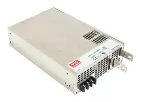
RSP-2400-12
AC/DC Enclosed Power Supply (PSU), ITE, 1 Outputs, 2.0004 kW, 12 VDC, 166.7 A
⚠️ Reference pricing provided. In case of supply shortages, we will connect you with our trusted procurement partners to ensure your project's continuity.
- Manufacturer: MEAN WELL
- Product type: AC / DC Enclosed Power Supplies
- No. of Outputs:1Outputs; Output Power Max:2.0004kW; Output Voltage - Output 1:12V; Output Current - Output 1:166.7A; Output Voltage - Output 2:-; Output Current - Output 2:-; Output Volt
- SVHC: No SVHC (25-Jun-2025)
- Product Range: RSP-2400 Series
- No. of Outputs: 1Outputs
- Output Power Max: 2.0004kW
- Input Voltage VAC: 90V AC to 264V AC
- Power Supply Output Type: Adjustable, Fixed
- Output Current - Output 1: 166.7A
- Output Current - Output 2: -
- Output Current - Output 3: -
- Output Current - Output 4: -
- Output Voltage - Output 1: 12VDC
- Output Voltage - Output 2: -
- Output Voltage - Output 3: -
- Output Voltage - Output 4: -
- Power Supply Applications: ITE
| Delivery and price | |
|---|---|
| Units per pack | 5 |
| Price | 347.52 € |
| Current stock | 10+ |
| Lead time | 30 days |
Datasheet

**RSP - 2400 series**

2400W Power Supply with Single Output

## ■

**==> picture [184 x 61] intentionally omitted <==**

**----- Start of picture text -----**<br>
BauarSicherheitbeegelodwacmat geprufto ges g<br>GALs L S www.ID 2000000000 ) tuv.com HHL CB C€<br>■ Certificates<br>**----- End of picture text -----**<br>


**==> picture [13 x 11] intentionally omitted <==**

**----- Start of picture text -----**<br>
■<br>**----- End of picture text -----**<br>


**==> picture [13 x 11] intentionally omitted <==**

**----- Start of picture text -----**<br>
■<br>**----- End of picture text -----**<br>


℃

**==> picture [13 x 11] intentionally omitted <==**

**----- Start of picture text -----**<br>
■<br>**----- End of picture text -----**<br>


_File Name:RSP-2400-SPEC   2018-10-04_

**RSP - 2400 series**

2400W Power Supply with Single Output

## **SPECIFICATION**

|**SPECIFICATION**|**SPECIFICATION**||||
|---|---|---|---|---|
|**RSP-2400-12**<br>**MODEL**<br>**DC VOLTAGE**<br>**RATED CURRENT**<br>**CURRENT RANGE**<br>**RATED POWER**<br>**OUTPUT**<br>**VOLTAGE ADJ. RANGE**<br>**LINE REGULATION**<br>**LOAD REGULATION**<br>**SETUP, RISE TIME**<br>**HOLD UP TIME (Typ.)**<br>**VOLTAGE RANGE**<br>**FREQUENCY RANGE**<br>**EFFICIENCY (Typ.)**<br>**INPUT**<br>**INRUSH CURRENT (Typ.)**<br>**LEAKAGE CURRENT**<br>**OVER TEMPERATURE**<br>**OUTPUT VOLTAGE**<br>**PROGRAMMABLE(PV)**<br>**WORKING TEMP.**<br>**WORKING HUMIDITY**<br>**STORAGE TEMP., HUMIDITY**<br>**TEMP. COEFFICIENT**<br>**VIBRATION**<br>**MTBF**<br>**DIMENSION**<br>**OTHERS**<br>**NOTE**<br>**PACKING**<br>**OVERLOAD (OLP)**<br>**OVER VOLTAGE**<br>**AC CURRENT (Typ.)**<br>12V<br>166.7A<br>0 ~ 166.7A<br>2000.4W<br>150mVp-p<br>10.8 ~ 13.2V<br>±1.0%<br>±0.5%<br>±0.5%<br>1000ms, 80ms at full load<br>12ms at full load<br>180 ~ 264VAC          254 ~ 370VDC<br>47 ~ 63Hz<br>88%<br>15.5A/180VAC          12A/230VAC<br>60A/230VAC<br><2.0mA / 240VAC<br>100 ~ 112% rated output power<br>13.8 ~ 16.8V<br>User adjustable continuous constant current limiting or constant current limiting with delay shutdown after 5 seconds, re-power on to recover<br>28.8 ~ 33.6V<br>57.6 ~ 67.2V<br>Protection type : Shut down o/p voltage, re-power on to recover<br>Shut down o/p voltage, recovers automatically after temperature goes down<br>-20 ~ +70<br>(Refer to "Derating Curve")<br>℃<br>20 ~ 90% RH non-condensing<br>-40 ~ +85<br>, 10 ~ 95% RH non-condensing<br>℃<br>±<br>℃<br>℃<br>0.05%/<br>(0 ~ 50<br>)<br>10 ~ 500Hz, 2G 10min./1cycle, 60min. each along X, Y, Z axes<br>234.1K hrs min.<br>Telcordia SR-332 (Bellcore) ; 83.9K hrs min.      MIL-HDBK-217F (25<br>)<br>℃<br>278*177.8*63.5mm (L*W*H)<br>3.3Kg; 4pcs/14.2Kg/1.81CUFT<br>90.5%<br>91.5%<br>±0.5%<br>±0.5%<br>±0.5%<br>±0.5%<br>±1.0%<br>±1.0%<br>150mVp-p<br>22 ~ 28V<br>200mVp-p<br>43 ~ 56V<br>24V<br>100A<br>0 ~ 100A<br>2400W<br>48V<br>50A<br>0 ~ 50A<br>2400W<br>**RSP-2400-24**<br>**RSP-2400-48**<br>℃<br>℃<br>℃<br>**POWER FACTOR (Typ.)**<br>0.95/230VAC at full load<br>**SAFETY STANDARDS**<br>UL60950-1, TUV EN60950-1, EAC TP TC 004,<br>approved<br>BSMI CNS14336-1<br>**RIPPLE & NOISE (max.) Note.2**<br>**VOLTAGE TOLERANCE Note.3**<br>**WITHSTAND VOLTAGE**<br>**ISOLATION RESISTANCE**<br>I/P-O/P:3KVAC     I/P-FG:2KVAC     O/P-FG:0.5KVAC<br>I/P-O/P, I/P-FG, O/P-FG:100M Ohms / 500VDC / 25<br>/ 70% RH<br>℃<br>**ENVIRONMENT**<br>**SAFETY &**<br>**FUNCTION**<br>**EMC**<br>**(Note 4)**<br>**PROTECTION**<br>**ALARM SIGNAL OUTPUT**<br>**REMOTE ON-OFF CONTROL**<br>**AUXILIARY POWER**<br>Please refer to the Function Manual<br>Power OK signal. Please refer to the Function Manual<br>12V@0.1A(Only for Remote ON-OFF control)<br>Please refer to the Function Manual.<br>**REMOTE SENSE**<br>Compensate voltage drop on the load wiring up to 0.25V. Please refer to the Function Manual.<br>**Parameter**<br>**Parameter**<br>ESD<br>Radiated<br>EFT / Burst<br>Surge<br>Conducted<br>Magnetic Field<br>Voltage Dips and Interruptions<br>Conducted<br>Radiated<br>Harmonic Current<br>Voltage Flicker<br>EN55024 , EN61204-3, EN61000-6-2, BSMI CNS13438<br>**Standard**<br>**Standard**<br>EN55032 (CISPR32) / EN55011 (CISPR11)<br>EN55032 (CISPR32) / EN55011 (CISPR11)<br>EN61000-3-2<br>EN61000-3-3<br>EN61000-4-2<br>EN61000-4-3<br>EN61000-4-4<br>EN61000-4-5<br>EN61000-4-6<br>EN61000-4-8<br>EN61000-4-11<br>**Test Level / Note**<br>**Test Level / Note**<br>Level 3, 8KV air ; Level 2, 4KV contact<br>Level 3<br>Level 3<br>Level 3<br>Level 4<br>>95% dip 0.5 periods, 30% dip 25 periods,<br>>95% interruptions 250 periods<br>Class B<br>Class A<br>-----<br>-----<br>**EMC IMMUNITY**<br>**EMC EMISSION**<br>4.8 ~ 28V<br>9.6 ~ 56V<br>2.4 ~ 13.2V<br>**CURRENT SHARING**<br>Up to 7200W or (2+1) units. Please refer to the Function Manual.<br>Level 3, 2KV/Line-Earth ; Level 2, 1KV/Line-Line<br>as<br>RR<br>1. All parameters NOT specially mentioned are measured at230VAC input, rated load and 25 _ of ambient temperature.<br>2. Ripple & noise are measured at 20MHz of bandwidth by using a 12" twisted pair-wire terminated with a 0.1uf & 47uf parallel capacitor.<br>3. Tolerance<br>: includes set up tolerance, line regulation and load regulation.<br>4. The power supply is considered a component which will be installed into a final equipment. All the EMC tests are been executed by mounting the unit on<br>a 720mm*360mm metal plate with 1mm of thickness. The final equipment must be re-confirmed that it still meets EMC directives. For guidance on how to<br>perform these EMC tests, please refer to “EMI testing of component power supplies.” (as available on http://www.meanwell.com)<br>5. The ambient temperature derating of 3.5<br>/1000m with fanless models and of<br>5<br>/1000m with fan models for operating altitude higher than 2000m(6500ft).||**RSP-2400-12**|**RSP-2400-24**|**RSP-2400-48**|
||**DC VOLTAGE**|12V|24V|48V|
||**RATED CURRENT**|166.7A|100A|50A|
||**CURRENT RANGE**|0 ~ 166.7A|0 ~ 100A|0 ~ 50A|
||**RATED POWER**|2000.4W|2400W|2400W|
||**RIPPLE & NOISE (max.) Note.2**|150mVp-p|150mVp-p|200mVp-p|
||**VOLTAGE ADJ. RANGE**|10.8 ~ 13.2V|22 ~ 28V|43 ~ 56V|
||**VOLTAGE TOLERANCE Note.3**|±1.0%|±1.0%|±1.0%|
||**LINE REGULATION**|±0.5%|±0.5%|±0.5%|
||**LOAD REGULATION**|±0.5%|±0.5%|±0.5%|
||**SETUP, RISE TIME**|1000ms, 80ms at full load|||
||**HOLD UP TIME (Typ.)**|12ms at full load|||
||**VOLTAGE RANGE**|180 ~ 264VAC          254 ~ 370VDC|||
||**FREQUENCY RANGE**|47 ~ 63Hz|||
||**POWER FACTOR (Typ.)**|0.95/230VAC at full load|||
||**EFFICIENCY (Typ.)**|88%|90.5%|91.5%|
||**AC CURRENT (Typ.)**|15.5A/180VAC          12A/230VAC|||
||**INRUSH CURRENT (Typ.)**|60A/230VAC|||
||**LEAKAGE CURRENT**|<2.0mA / 240VAC|||
||**OVERLOAD (OLP)**|100 ~ 112% rated output power<br>User adjustable continuous constant current limiting or constant current limiting with delay shutdown after 5 seconds, re-power on to recover|||
||**OVER VOLTAGE**|13.8 ~ 16.8V<br>28.8 ~ 33.6V<br>57.6 ~ 67.2V<br>Protection type : Shut down o/p voltage, re-power on to recover|||
||**OVER TEMPERATURE**|Shut down o/p voltage, recovers automatically after temperature goes down|||
||**OUTPUT VOLTAGE**<br>**PROGRAMMABLE(PV)**|Please refer to the Function Manual.<br>4.8 ~ 28V<br>9.6 ~ 56V<br>2.4 ~ 13.2V|||
||**CURRENT SHARING**|Up to 7200W or (2+1) units. Please refer to the Function Manual.|||
||**AUXILIARY POWER**|12V@0.1A(Only for Remote ON-OFF control)|||
||**REMOTE ON-OFF CONTROL**|Please refer to the Function Manual|||
||**REMOTE SENSE**|Compensate voltage drop on the load wiring up to 0.25V. Please refer to the Function Manual.|||
||**ALARM SIGNAL OUTPUT**|Power OK signal. Please refer to the Function Manual|||
||**WORKING TEMP.**|-20 ~ +70<br>(Refer to "Derating Curve")<br>℃|||
||**WORKING HUMIDITY**|20 ~ 90% RH non-condensing|||
||**STORAGE TEMP., HUMIDITY**|-40 ~ +85<br>, 10 ~ 95% RH non-condensing<br>℃|||
||**TEMP. COEFFICIENT**|±<br>℃<br>℃<br>0.05%/<br>(0 ~ 50<br>)|||
||**VIBRATION**<br>as|10 ~ 500Hz, 2G 10min./1cycle, 60min. each along X, Y, Z axes|||
||**SAFETY STANDARDS**<br>as|UL60950-1, TUV EN60950-1, EAC TP TC 004,<br>approved<br>BSMI CNS14336-1|||
||**WITHSTAND VOLTAGE**<br>as<br>RR|I/P-O/P:3KVAC     I/P-FG:2KVAC     O/P-FG:0.5KVAC|||
||**ISOLATION RESISTANCE**<br>RR|I/P-O/P, I/P-FG, O/P-FG:100M Ohms / 500VDC / 25<br>/ 70% RH<br>℃|||
||**MTBF**<br>**EMC IMMUNITY**<br>**EMC EMISSION**<br>RR|**Parameter**|**Standard**|**Test Level / Note**|
|||Conducted|EN55032 (CISPR32) / EN55011 (CISPR11)|Class B|
|||Radiated|EN55032 (CISPR32) / EN55011 (CISPR11)|Class A|
|||Harmonic Current|EN61000-3-2|-----|
|||Voltage Flicker|EN61000-3-3|-----|
|||EN55024 , EN61204-3, EN61000-6-2, BSMI CNS13438|||
|||**Parameter**|**Standard**|**Test Level / Note**|
|||ESD|EN61000-4-2|Level 3, 8KV air ; Level 2, 4KV contact|
|||Radiated|EN61000-4-3|Level 3|
|||EFT / Burst|EN61000-4-4|Level 3|
|||Surge|EN61000-4-5|Level 3, 2KV/Line-Earth ; Level 2, 1KV/Line-Line|
|||Conducted|EN61000-4-6|Level 3|
|||Magnetic Field|EN61000-4-8|Level 4|
|||Voltage Dips and Interruptions|EN61000-4-11|>95% dip 0.5 periods, 30% dip 25 periods,<br>>95% interruptions 250 periods|
|||234.1K hrs min.<br>Telcordia SR-332 (Bellcore) ; 83.9K hrs min.      MIL-HDBK-217F (25<br>)<br>℃|||
||**DIMENSION**|278*177.8*63.5mm (L*W*H)|||
||**PACKING**<br>3.3Kg; 4pcs/14.2Kg/1.81CUFT<br>℃<br>℃<br>℃<br>1. All parameters NOT specially mentioned are measured at230VAC input, rated load and 25 _ of ambient temperature.<br>2. Ripple & noise are measured at 20MHz of bandwidth by using a 12" twisted pair-wire terminated with a 0.1uf & 47uf parallel capacitor.<br>3. Tolerance<br>: includes set up tolerance, line regulation and load regulation.<br>4. The power supply is considered a component which will be installed into a final equipment. All the EMC tests are been executed by mounting the unit on<br>a 720mm*360mm metal plate with 1mm of thickness. The final equipment must be re-confirmed that it still meets EMC directives. For guidance on how to<br>perform these EMC tests, please refer to “EMI testing of component power supplies.” (as available on http://www.meanwell.com)<br>5. The ambient temperature derating of 3.5<br>/1000m with fanless models and of<br>5<br>/1000m with fan models for operating altitude higher than 2000m(6500ft).||||


℃ /1000m with fanless models and of 5 ℃ /1000m with fan models for operating altitude higher than 2000m(6500ft).

_File Name:RSP-2400-SPEC   2018-10-04_

## 2400W Power Supply with Single Output

## **RSP - 2400 series**

## **Block Diagram**

**==> picture [461 x 169] intentionally omitted <==**

**----- Start of picture text -----**<br>
PFC fosc : 88KHz<br>PWM fosc : 100KHz<br>+S<br>I/P FILTEREMI CURRENTLIMITINGINRUSHACTIVE RECTIFIERSPFC& SWITCHINGPOWER RECTIFIERSFILTER& +V-V<br>-S<br>PFC O.V.P.<br>CONTROL O.L.P.<br>PV<br>PWM<br>DETECTION<br>O.T.P. CONTROL CIRCUIT P OK<br>LOAD CONTROLREMOTE RC<br>SHARING<br>CS<br>FAN<br>AUX RECTIFIERS<br>POWER & AUX POWER<br>FILTER<br>**----- End of picture text -----**<br>


## **Static Characteristics**

**==> picture [479 x 352] intentionally omitted <==**

**----- Start of picture text -----**<br>
100<br>MODEL<br>90 INPUT 12V 24V 48V<br>80 180~264VAC 2000.4W 2400W 2400W<br>166.7A 100A 50A<br>70<br>60<br>50<br>180 185 190 195 200 210 220 230 240 250 264<br>INPUT VOLTAGE (V) 60Hz<br>Derating Curve Efficiency vs Load (48V Model)<br>92<br>100 90<br>88<br>80<br>86<br>60 84<br>50 82<br>40 80<br>78<br>20<br>76<br>10% 20% 30% 40% 50% 60% 70% 80% 90% 100%<br>-20 0 10 20 30 40 50 60 70 (HORIZONTAL)<br>AMBIENT TEMPERATURE ( ℃ ) LOAD<br>※ The curve above is measured at 230VAC.<br>LOAD (%)<br>EFFICIENCY (%)<br>LOAD (%)<br>**----- End of picture text -----**<br>


_File Name:RSP-2400-SPEC   2018-10-04_

**RSP - 2400 series**

2400W Power Supply with Single Output

## **Function Manual**

## **1. Remote Sense**

**==> picture [487 x 214] intentionally omitted <==**

**----- Start of picture text -----**<br>
※ The Remote Sense compensates voltage drop on the load wiring up to 0.25V<br>CN2<br>+V<br>PIN7 -S PIN8 +S<br>+V LOAD<br>-V<br>-V Sense lines should be twisted in pairs to minimize<br>noise pick-up.<br>※ Caution: The power supply, by factory default(also the assumption for other sections), is shipped with, -S & -V on CN2, as well as +S & +V, shorted by<br>connector. When activating the Remote Sense, the +S signal should be connected to the positive terminal of the load whereas -S signal to<br>the negative terminal.<br>2. Output Voltage Programming (or, PV / remote voltage programming / remote adjust / margin programming / dynamic voltage trim)<br>※ In addition to the adjustment via the built-in potentiometer, the output voltage can be trimmed to 20~110%(Typ.) of the nominal voltage by applying<br>EXTERNAL VOLTAGE.<br>**----- End of picture text -----**<br>


**==> picture [366 x 102] intentionally omitted <==**

**----- Start of picture text -----**<br>
CN2<br>PIN7 -S PIN8 +S<br>+V<br>PIN3 PV<br>-V EXTERNAL VOLTAGE (DC)<br>PIN5 -S<br>◎ Connecting an external DC source  between PV & -S on CN2, and +S & +V, -S & -V  also need to be connected as exhibited above.<br>**----- End of picture text -----**<br>


**==> picture [477 x 231] intentionally omitted <==**

**----- Start of picture text -----**<br>
Vout<br>OVP >120%<br>120<br>100 100<br>80 Non-Linear 80<br>MODEL 12V 24V 48V<br>60 60<br>PV Range 2.4 ~ 13.2V 4.8 ~ 28V 9.6 ~ 56V<br>40 40<br>20 20<br>V V<br>1 2 3 4 5 6 20 40 60 80 100 120<br>EXTERNAL VOLTAGE (DC) OUTPUT VOLTAGE (%)<br>◎ Please do not adopt PWM signal as the EXTERNAL VOLTAGE. ◎ The rated current should change with the<br>Output Voltage Programming accordingly.<br>※ Caution: (1)By factory default, the Output Voltage Programming is not activated, and PV(PIN3) and PS(PIN4) of CN2 are shorted by connector. Whenever<br>this function is not needed to activate, as assumed in other sections’ diagrams, please keep PV(PIN3) and PS(PIN4) of CN2 shorted ; otherwise,<br>the power supply will have no output.<br>(2) PV(PIN3) and PS(PIN4) of CN1 or CN2 must be disconnected if “Output Voltage Programming” function is used; otherwise, the internal<br>electrical components may be damaged, and the power supply unit may thus be out of order.<br>OUTPUT VOLTAGE (%) OUTPUT CURRENT (%)<br>**----- End of picture text -----**<br>


_File Name:RSP-2400-SPEC   2018-10-04_

**RSP - 2400 series**

## 2400W Power Supply with Single Output

## **3.Remote ON-OFF**

※ Remote ON-OFF is activated by the configuration with respect to CN1,CN2 and CN3 as shown in the following diagram.

**==> picture [474 x 609] intentionally omitted <==**

**----- Start of picture text -----**<br>
CN2<br>PIN1 RCG PIN2 RC<br>CN3<br>PIN7 AUXG PIN8 AUX<br>◎ By factory default, PV(PIN3) and PS(PIN4 ) on CN2 are<br>shorted by connector; likewise, OLP(PIN9) and OL-SD(PIN10)<br>on CN3 are shorted when shipped.<br>Example 3.2(A): Using external voltage source<br>AUX<br>12V<br>1KΩ RC<br>Internal<br>12V typ. SW<br>RCG<br>AUXG<br>Example 3.2(B): Using internal 12V auxiliary output<br>AUX<br>1KΩ RC<br>Internal<br>12V typ.<br>RCG<br>SW<br>AUXG<br>Example 3.2(C): Using internal 12V auxiliary output<br>AUX<br>1KΩ<br>1KΩ RC<br>Internal<br>12V typ. SW<br>RCG<br>AUXG<br>◎ Connection Method<br>Example 3.2(A) Example 3.2(B) Example 3.2(C)<br>Power supply output ON SW Open SW Open SW Close<br>SW Logic<br>Power supply output OFF SW Close SW Close SW Open<br>**----- End of picture text -----**<br>


_File Name:RSP-2400-SPEC   2018-10-04_

**RSP - 2400 series**

2400W Power Supply with Single Output

## **4.Alarm Signal Output**

※ Alarm signal is sent out through " _P OK_ " & " _P OK GND_ " and _P OK2 & P OK GND2_ pins on CN3. Please acknowledge an external voltage source is required for this function.

**==> picture [445 x 319] intentionally omitted <==**

**----- Start of picture text -----**<br>
CN3<br>PIN3 P OK GND2 PIN4 P OK2<br>PIN1 P OK GND PIN2 P OK<br>◎ By factory default, OLP(PIN9) and OL-SD(PIN10)<br>on CN3 are shorted by connector when shipped.<br>Function Description Output of alarm(P OK, Relay Contact) Output of alarm(P OK2, TTL Signal)<br>The signal is "Low" when the power supply is above Low Low<br>80% of the rated output voltage, or, say, Power OK (0.5V max at 500mA) (0.5V max at 10mA)<br>P OK<br>The signal turns to be "High" when the power supply<br>High or open High or open<br>is under 80% of the rated output voltage, or, say,<br>Power Fail (External applied voltage, 500mA max.) (External applied voltage, 10mA max.)<br>Table 4.1 Explanation of alarm<br>P OK P OK2<br>R R<br>V 0.1uF V<br>P OK GND External voltage and R P OK GND2 External voltage and R<br>(The max. sink is 500mA and 20V) (The max. sink is 10mA and 30V)<br>Fig. 4.1 Internal circuit of P OK (Relay, total is 10W) Fig. 4.2 Internal circuit of P OK2 (Open collector method)<br>**----- End of picture text -----**<br>


_File Name:RSP-2400-SPEC   2018-10-04_

**RSP - 2400 series**

2400W Power Supply with Single Output

## **5.Select Overload Protection Type**

(1)Insert the shorting connector on CN3 that is shown in Fig 5.1, the Overload Protection Type will be "constant current limiting with delay shutdown after 5 seconds, re-power on to recover". This is  the factory default.

(2)Remove the shorting connector on CN3 that is shown in Fig 5.2, the Overload Protection Type will be "continuous constant current limiting".

**==> picture [331 x 29] intentionally omitted <==**

**----- Start of picture text -----**<br>
OL-SD OL-SD<br>OLP OLP<br>**----- End of picture text -----**<br>


Fig. 5.1 Insert the CN3

Fig. 5.2 Remove the CN3

Overload Protection Type : constant current  limiting with delay shutdown after 5 seconds Overload Protection Type : constant current  limiting

## **6.Current Sharing with Remote Sense**

RSP-2400 has the built-in active current sharing function and can be connected in parallel, up to 3 units, to provide higher output power as exhibited below :

- ※ The power supplies should be paralleled using short and large diameter wiring and then connected to the load. ※ Difference of output voltages among parallel units should be less than 0.2V.

- ※ The total output current must not exceed the value determined  by the following equation:

Maximum output current at parallel operation=(Rated current per unit)×(Number of unit)×0.9

※ When the total output current is less than 3% of the total rated current, or say (3% of Rated current per unit)×(Number of unit) the current shared among units may not be fully balanced.

**==> picture [308 x 370] intentionally omitted <==**

**----- Start of picture text -----**<br>
No.1(Master)<br>◎<br>+V ◎<br>-V<br>AC/L AC/N<br>+S<br>No.2(Slave) +V<br>Load<br>-V<br>-S<br>+V<br>-V<br>AC/L AC/N<br>No.3(Slave)<br>+V<br>-V<br>AC/L AC/N<br>**----- End of picture text -----**<br>


- When remote sensing is used in parallel operation, the sensing wire must be connected only to the master unit

- Sense lines should be twisted in pairs to minimize noise pick-up.

◎ _+S,-S_ and _CS_ on CN1 or CN2are connected mutually in parallel. ◎ Under parallel operation, the "output voltage programming" function is not available.

_File Name:RSP-2400-SPEC   2018-10-04_

**RSP - 2400 series**

2400W Power Supply with Single Output

## **6.Three Phase Connect**

**==> picture [433 x 161] intentionally omitted <==**

**----- Start of picture text -----**<br>
Users can exploit three units of RSP-2400(unit 1 ,unit 2,unit 3) to work with 3ψ power system. Please refer to following diagrams for configuration.<br>※ FIG. A: 3 ψ 3 wire 220VAC SYSTEM<br>R<br>unit 1<br>L1<br>FG1<br>N1<br>unit 2<br>L2<br>FG2<br>N2<br>unit 3<br>L3<br>S FG3<br>N3<br>FG<br>T<br>220V<br>220V<br>**----- End of picture text -----**<br>


## ※ **FIG. B: 3** ψ **4 wire 220/380VAC SYSTEM**

**==> picture [242 x 130] intentionally omitted <==**

**----- Start of picture text -----**<br>
R unit 1<br>L1<br>FG1<br>N1<br>unit 2<br>L2<br>FG2<br>N2<br>N unit 3<br>L3<br>FG3<br>N3<br>S<br>FG<br>T<br>220V<br>380V<br>**----- End of picture text -----**<br>


## ※ **FIG. C: 3** ψ4 **wire 190/110VAC SYSTEM**

**==> picture [291 x 129] intentionally omitted <==**

**----- Start of picture text -----**<br>
R<br>unit 1<br>L1<br>FG1<br>N1<br>unit 2<br>L2<br>N FG2<br>(N.C.) N2<br>unit 3<br>L3<br>S FG3<br>N3<br>FG<br>T<br>110V<br>190V<br>**----- End of picture text -----**<br>


_File Name:RSP-2400-SPEC   2018-10-04_

## 2400W Power Supply with Single Output

## **RSP - 2400 series**

## **Mechanical Specification**

**==> picture [412 x 261] intentionally omitted <==**

**----- Start of picture text -----**<br>
Case No.982B           Unit:mm<br>278<br>236.3 27 40<br>2-M4<br>1 1 CN1 CN2 CN3<br>8 6 4 2 8 6 4 2 10 8 6 4 2<br>7 5 3 1 7 5 3 1 9 7 5 3 1<br>8-M4(Both Sides) L=5mm M3<br>236.3 27<br>OUTPUT<br>4-M4 L=5mm +V<br>1 1<br>-V<br>87 65CN143 21 87CN265 43 21 109CN387 65 43 21<br>Air flow<br>direction<br>INPUT<br>1 1<br>16max.<br>ψ8.5<br>177.8<br>TB1<br>10<br>13<br>LED<br>12.5<br>38 63.5<br>20<br>7.9<br>162<br>4<br>SVR +<br>3<br>2<br>1<br>**----- End of picture text -----**<br>


## ※ Mounting Instruction

Chassis of RSP-2400 Hole No. Recommended Screw Size MAX. Penetration Depth **L** Recommended mounting torque Mounting Surface 1 M4 5mm 7~1  K0 gf-cm ※ Control Pin No. Assignment (CN1,CN2) : HRS DF11-8DP-2DS or equivalent Mounting Screw 8 2 **L** Mating Housing HRS DF11-8DS or equivalent Terminal HRS DF11-**SC or equivalent 7 1

## ◎ CN1 and CN2 are connected internally.

|**Pin No.**|**Function**|**Description**|
|---|---|---|
|1|RCG|Remote ON-OFF Ground|
|2|RC|Remote ON-OFF|
|3|PV|Connection for output voltage programming|
|4|PS|Reference Voltage Terminal|
|5,7|-S|Negative sensing for remote sense|
|6|CS(Current Share)|Current Share|
|8|+S|Postive sensing for remote sense|


_File Name:RSP-2400-SPEC   2018-10-04_

**RSP - 2400 series**

2400W Power Supply with Single Output

**==> picture [455 x 197] intentionally omitted <==**

**----- Start of picture text -----**<br>
※Control Pin No. Assignment (CN3) : HRS DF11-10DP-2DS or equivalent<br>10 2<br>Mating Housing HRS DF11-10DS or equivalent<br>Terminal HRS DF11-**SC or equivalent<br>9 1<br>Pin No. Function Description<br>1 P OK GND Power OK Ground<br>2 P OK Power OK Signal (Relay Contact)<br>3 P OK GND2 Power OK Ground<br>4 P OK2 Power OK Signal (TTL Signal)<br>5 RCG Remote ON-OFF Ground<br>6 RC Remote ON-OFF<br>7 AUXG Auxiliary Ground<br>8 AUX Auxiliary Output<br>9 OLP<br>Overload(OLP) type select<br>10 OL-SD<br>**----- End of picture text -----**<br>


※AC Input Terminal Pin No. Assignment Pin No. Assignment Diagram Maximum mounting torque 1 AC/L 2 AC/N 18Kgf-cm 3 FG

## **Installation Manual**

Please refer to : http://www.meanwell.com/manual.html

_File Name:RSP-2400-SPEC   2018-10-04_
Updated at June 6, 2026
About Novapart
Novapart is a B2B electronic component broker specialising in stock shortages and cost reduction. We source hard-to-find parts and identify compliant alternatives across a catalogue of 410,000+ components from 500+ manufacturers.
Learn more →Stock Shortage Specialist
When a component is unavailable, discontinued or has an unacceptable lead time, we tap into our network of vetted European and Asian distributors to source what you need — without compromising on quality or traceability.
Request a quote →Compliant Alternatives
We identify pin-to-pin, electrically equivalent substitutes that meet the same certifications (RoHS, AEC-Q100, REACH) as your original specification — validated against datasheets, not just part numbers. Often at a lower cost.
BOM Analysis service →