
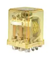


RR3B-ULCDC24V
POWER RELAY, 24VDC, 10A, 3PDT, SOCKET
- Manufacturer: IDEC
- Product type: Power Relays
- Contact Configuration:3PDT; Coil Voltage:24VDC; Contact Current:10A; Product Range:RR Series; Relay Mounting:Socket; Coil Type:Non Latching; Contact Voltage VAC: 31B3333
- Coil Type: Non Latching
- Coil Voltage: 24VDC
- Product Range: RR Series
- Relay Mounting: Socket
- Coil Resistance: 400ohm
- Contact Current: 10A
- Relay Terminals: Quick Connect
- Contact Material: Silver
- Contact Voltage VAC: 110V
- Contact Voltage VDC: 30V
- Contact Configuration: 3PDT
| Delivery and price | |
|---|---|
| Units per pack | 250 |
| Price | 15.75 € |
| Current stock | 10+ |
| Lead time | 30 days |
**Relays  & Sockets**

**RR**

**RR Series Power Relays**

## **Key features:**

- SPDT through 3PDT, 10A contacts

- Midget power type relays

- Available in pin and blade terminal styles.

- Options include an indicator, check button for test operations and side flange.

- DIN rail, surface and panel mount sockets are available for a wide a variety of mounting applications.

## **Part Number Selection**

**==> picture [489 x 257] intentionally omitted <==**

**----- Start of picture text -----**<br>
Part Number<br>Coil Voltage Code<br>Contact Model Pin Terminal Blade Terminal*<br>(Standard Stock Items in Bold)<br>SPDT Standard RR1BA-U  0<br>With Indicator RR1BA-UL  0<br>With Check Button — RR1BA-UC  0<br>With Indicator and Check Button RR1BA-ULC  0<br>Side Flange Model RR1BA-US  0<br>DPDT Standard RR2P-U  0 RR2BA-U  0<br>With Indicator RR2P-UL  0 RR2BA-UL  0<br>With Check Button RR2P-UC  0 RR2BA-UC  0 AC6V, AC12V, AC24V, AC110V, AC240V,  AC120V ,<br>With Indicator and Check Button RR2P-ULC  0 RR2BA-ULC  0 DC6V, DC12V,  DC24V , DC48V, DC110V<br>Side Flange Model — RR2BA-US  0<br>3PDT Standard RR3PA-U  0 RR3B-U  0<br>With Indicator RR3PA-UL  0 RR3B-UL  0<br>With Check Button RR3PA-UC  0 RR3B-UC  0<br>With Indicator and Check Button RR3PA-ULC  0 RR3B-ULC  0<br>Side Flange Model — RR3B-US  0<br>**----- End of picture text -----**<br>


- *Blade type not TUV tested or CE marked.

**Ordering Information** When ordering, specify the Part No. and coil voltage code: (example) **RR3B-U       AC120V** Part No.                         Coil Voltage Code ~~——~~ Fo All DIN rail mount sockets shown here can be mounted using DIN rail BNDN1000.

Side flange model mounts directly to panel with no socket required.

## **Sockets**

Relays Standard DIN Rail Mount Finger-safe DIN Rail Mount Through Panel Mount SR2P-05 RR2P SR2P-05C SR2P-51 SR2P-06 SR3P-05 RR3PA SR3P-05C SR3P-51 SR3P-06 RR1BA RR2BA SR3B-05 — SR3B-51 RR3B

1705242125

**800-262-IDEC** (4332) • USA & Canada

883

**Relays & Sockets**

**RR**

## **Hold Down Springs & Clips**

|Appearance|||Description<br>Pullover Wire<br>Spring|Relay<br>RR2P<br>RR3PA<br>RR1BA, RR2BA,<br>RR3B|For DIN<br>Mount Socket<br>SR2B-02F1<br>SR3B-02F1<br>SR3B-02F1|For Through Panel &<br>PCB Mount Socket<br>SR3P-01F1<br>SR3B-02F1|
|---|---|---|---|---|---|---|
||||||||
|.|.||Leaf Spring<br>(side latch)|RR2P, RR3PA|SFA-203|–|


## **Accessories**

|Item<br>Aluminum<br>DIN Rail<br>(1 meter length)|Appearance<br>Use with<br>All DIN rail sockets<br>~~ee~~<br>al|Appearance<br>Use with<br>All DIN rail sockets<br>~~ee~~<br>al|Part No.<br>BNDN1000|Remarks<br>The BNDN1000 is designed to accommodate DIN mount sockets.<br>Made of durable extruded aluminum, the BNDN1000 measures 0.413<br>(10.5mm) in height and 1.37 (35mm) in width (DIN standard). Standard<br>length is 39” (1,000mm).|
|---|---|---|---|---|
|DIN Rail End<br>Stop<br>Replacement<br>Hold-Down<br>Spring Anchor|ee<br>~~(i,~~|DIN rail<br>Horseshoe clip for sockets<br>SR3B-05, SR2P-06, SR3P-06<br>Chair clip for sockets<br>SR2P-05(C), SR3P-05(C)|BNL5<br>Y778-011<br>Y703-102|9.1 mm wide.<br>For use on DIN rail mount socket when using pullover wire hold down<br>spring. 2 pieces included with each socket.|


## —ipeEc

1705242125

**www.IDEC.com**

884

**Relays  & Sockets**

**RR**

## **Specifications**

|Contact Material<br>Contact Resistance1<br>Minimum Applicable Load<br>Operating Time<br>2<br>Release Time<br>2<br>Power Consumption (approx.)<br>Insulation Resistance<br>Dielectric<br>Strength<br>Pin Terminal<br>Blade Terminal<br>Operating Frequency<br>Vibration Resistance<br>Shock Resistance<br>Mechanical Life<br>Electrical Life<br>Operating Temperature3<br>Operating Humidity<br>Weight (approx.) (Standard type)|Silver<br>30 mΩ maximum<br>1V DC, 10 mA<br>25 ms maximum<br>25 ms maximum<br>AC: 3 VA (50 Hz), 2.5 VA (60 Hz)<br>DC: 1.5W<br>100 MΩ minimum (500V DC megger)<br>Between live and dead parts:<br>1500V AC, 1 minute<br>Between contact and coil:<br>1500V AC, 1 minute<br>Between contacts of different poles:<br>1500V AC, 1 minute<br>Between contacts of the same pole:<br>1000V AC, 1 minute<br>Between live and dead parts:<br>2000V AC, 1 minute<br>Between contact and coil:<br>2000V AC, 1 minute<br>Between contacts of different poles:<br>2000V AC, 1 minute<br>Between contacts of the same pole:<br>1000V AC, 1 minute<br>Electrical:<br>1800 operations/h maximum<br>Mechanical:<br>18,000 operations/h maximum<br>Damage limits:<br>10 to 55 Hz, amplitude 0.5 mm<br>Operating extremes:<br>10 to 55 Hz, amplitude 0.5 mm<br>Damage limits:<br>1000 m/s2(100g)<br>Operating extremes:<br>100 m/s2(10G)<br>10,000,000 operations<br>200,000 operations (220V AC, 5A)<br>–25 to +40°C (no freezing)<br>5 to 85% RH (no condensation)<br>RR2P: 90g, RR3PA: 96g, RR1BA/RR2BA/RR3B: 82g|
|---|---|


## **Coil Ratings**

Rated Current (mA) ±15% (at 20°C) Operating Characteristics (values at 20°C) Coil Resistance (Ω) Rated Voltage (V) 50 Hz 60 Hz ±10% (at 20°C) Maximum Continuous Pickup Voltage Dropout Voltage Applied Voltage 6 490 420 4.9 ~~a a~~ 12 245 210 18 ~~|~~ AC ~~|~~ 24 | 121 | 105 79 | | | 110% 80% maximum 30% minimum (50/60 Hz) 110 27 23 1,680 ~~||||~~ 120 24 20.5 2,100 ~~|~~ | | | | | | 240 12.1 10.5 8,330 || ~~||~~ 6 240 25 || | | | | 12 120 100 DC 24 60 400 110% 80% maximum 10% minimum 48 30 1,600 ~~||~~ 110 13 8,460 ~~a~~

1705242125

**800-262-IDEC** (4332) • USA & Canada

885

**Relays & Sockets**

**RR**

## **Contact Ratings**

## **UL Ratings**

|Switches & Pilot Lights<br>Signaling Lights|**Contact Ratingsgss**<br>Maximum Contact Capacity<br>Continuous<br>Current<br>Allowable Contact Power<br>Rated Load<br>Resistive<br>Load<br>Inductive<br>Load<br>Voltage (V)<br>Res. Load<br>Ind. Load<br>10A<br>1650VA AC<br>300W DC<br>1100VA AC<br>150W DC<br>110 AC<br>10A<br>7.5A<br>220 AC<br>7.5A<br>5A<br>30 DC<br>10A<br>5A<br>Note: Inductive load for the rated load — cos ø = 0.3, L/R = 7 ms<br>**TÜV Ratings**<br>Voltage<br>~~———E~~<br>|<br>|<br>|<br>|<br>|<br>~~— ~~|<br>|<br>|<br>~~‘~~|**Contact Ratingsgss**<br>Maximum Contact Capacity<br>Continuous<br>Current<br>Allowable Contact Power<br>Rated Load<br>Resistive<br>Load<br>Inductive<br>Load<br>Voltage (V)<br>Res. Load<br>Ind. Load<br>10A<br>1650VA AC<br>300W DC<br>1100VA AC<br>150W DC<br>110 AC<br>10A<br>7.5A<br>220 AC<br>7.5A<br>5A<br>30 DC<br>10A<br>5A<br>Note: Inductive load for the rated load — cos ø = 0.3, L/R = 7 ms<br>**TÜV Ratings**<br>Voltage<br>~~———E~~<br>|<br>|<br>|<br>|<br>|<br>~~— ~~|<br>|<br>|<br>~~‘~~|**UL Ratings**<br>Voltage<br>Resistive<br>General use<br>Horse Power Rating<br>240V AC<br>10A<br>7A<br>1/3 HP<br>120V AC<br>10A<br>7.5A<br>1/4 HP<br>30V DC<br>10A<br>7A<br>—<br>**CSA Ratings**<br>Voltage<br>Resistive<br>General use<br>240V AC<br>10A<br>7A<br>120V AC<br>10A<br>7.5A<br>100V DC<br>—<br>0.5A<br>30V DC<br>10A<br>7.5A<br>~~rn~~<br>~~ee~~<br>~~ee~~<br>|<br>|<br>|<br>|<br>|<br>|<br>~~—___§~~|**UL Ratings**<br>Voltage<br>Resistive<br>General use<br>Horse Power Rating<br>240V AC<br>10A<br>7A<br>1/3 HP<br>120V AC<br>10A<br>7.5A<br>1/4 HP<br>30V DC<br>10A<br>7A<br>—<br>**CSA Ratings**<br>Voltage<br>Resistive<br>General use<br>240V AC<br>10A<br>7A<br>120V AC<br>10A<br>7.5A<br>100V DC<br>—<br>0.5A<br>30V DC<br>10A<br>7.5A<br>~~rn~~<br>~~ee~~<br>~~ee~~<br>|<br>|<br>|<br>|<br>|<br>|<br>~~—___§~~|**UL Ratings**<br>Voltage<br>Resistive<br>General use<br>Horse Power Rating<br>240V AC<br>10A<br>7A<br>1/3 HP<br>120V AC<br>10A<br>7.5A<br>1/4 HP<br>30V DC<br>10A<br>7A<br>—<br>**CSA Ratings**<br>Voltage<br>Resistive<br>General use<br>240V AC<br>10A<br>7A<br>120V AC<br>10A<br>7.5A<br>100V DC<br>—<br>0.5A<br>30V DC<br>10A<br>7.5A<br>~~rn~~<br>~~ee~~<br>~~ee~~<br>|<br>|<br>|<br>|<br>|<br>|<br>~~—___§~~|
|---|---|---|---|---|---|
|~~’~~|AC: cos ø = 1.0, DC: L/R = 0 ms<br>240V AC<br>10A<br>30V DC<br>10A<br>A<br>~~es a~~|||||


|~~es a~~|Relays<br>~~a~~|Terminal<br>~~a~~|Electrical Rating|Wire Size|Torque|
|---|---|---|---|---|---|
|DIN Rail<br>Sockets<br>Through<br>Panel Mount<br>Sockets<br>~~es a~~|SR2P-05<br>SR2P-05C<br>SR2P-06<br>SR3P-05<br>SR3P-05C<br>SR3P-06<br>SR3B-05<br>SR2P-51<br>SR3P-51<br>SR3B-51<br>~~a~~<br>~~|~~<br>~~|~~<br>~~|~~<br>~~|~~<br>~~|~~<br>|<br>|<br>|<br>|<br>|<br>|<br>|<br>|<br>|<br>|<br>||M3 screw with captive wire clamp<br>M3 screw with captive wire clamp, fingersafe<br>M3 screw with captive wire clamp<br>M3 screw with captive wire clamp<br>M3 screw with captive wire clamp, fingersafe<br>M3 screw with captive wire clamp<br>M3 screw with captive wire clamp<br>Solder<br>Solder<br>Solder<br>~~a~~<br>~~|~~<br>~~|~~<br>~~|~~<br>|<br>~~|~~<br>~~|~~<br>~~|~~<br>~~|~~<br>|<br>|<br>|<br>|<br>|<br>|<br>|<br>|<br>|<br>|<br>|<br>|<br>|<br>|<br>|<br>||300V, 10A<br>300V, 10A<br>300V, 10A<br>300V, 10A<br>300V, 10A<br>300V, 10A<br>300V, 15A (10A)* (*CSA rating)<br>300V, 10A<br>300V, 10A<br>300V, 10A<br>~~|~~<br>~~|~~<br>~~|~~<br>~~|~~<br>|<br>|<br>~~|~~<br>~~|~~<br>~~|~~<br>~~|~~<br>~~|~~<br>|<br>|<br>|<br>|<br>|<br>|<br>|<br>|<br>|<br>|<br>|<br>|<br>|<br>|<br>|<br>|<br>|<br>||Maximum 2 - #12 AWG<br>Maximum 2 - #12 AWG<br>Maximum 2 - #12 AWG<br>Maximum 2 - #12 AWG<br>Maximum 2 - #12 AWG<br>Maximum 2 - #12 AWG<br>Maximum 2 - #12 AWG<br>—<br>—<br>—<br>~~|~~<br>~~|~~<br>~~|~~<br>~~|~~<br>~~|~~<br>|<br>|<br>~~|~~<br>~~|~~<br>~~|~~<br>~~|~~<br>~~|~~<br>~~|~~<br>|<br>|<br>|<br>|<br>|<br>|<br>|<br>|<br>|<br>|<br>|<br>|<br>|<br>|<br>|<br>|<br>|<br>|<br>|<br>||9 - 11.5in•lbs<br>9 - 11.5in•lbs<br>9 - 11.5in•lbs<br>9 - 11.5in•lbs<br>9 - 11.5in•lbs<br>9 - 11.5in•lbs<br>9 - 11.5in•lbs<br>—<br>—<br>—<br>~~|~~<br>~~|~~<br>~~|~~<br>~~|~~<br>~~|~~<br>|<br>~~|~~<br>~~|~~<br>~~|~~<br>~~|~~<br>~~|~~<br>~~|~~<br>|<br>|<br>|<br>|<br>|<br>|<br>|<br>|<br>|<br>|<br>|<br>|<br>|<br>|<br>|<br>||


—ipeEc

1705242125

**www.IDEC.com**

886

**Relays  & Sockets**

**RR**

## **Characteristics (Reference Data)**

## Electrical Life Curves

**==> picture [473 x 290] intentionally omitted <==**

**----- Start of picture text -----**<br>
AC Load DC Load<br>1000 1000<br>500 500<br>30V DC<br>resistive<br>100 KL 100 NN<br>110V AC resistive<br>100V DC resistive<br>50 50<br>Se 220V AC resistive NNG PERN IAN<br>110V AC inductive 100V DC inductive<br>20 20<br>BEN 220V AC inductive EARN<br>30V DC inductive<br>10 Ff 10 eeeON<br>0.1 0.5 1 5 10 0.01 0.05 0.1 0.5 1 5 10<br>Load Current (A) Load Current (A)<br>Continuous Load Current vs. Operating Temperature Curve<br>Maximum Switching Capacity (Standard Type, With Check Button, and Side Flange Type)<br>10.0<br>AC<br>resistive 100<br>5.0 TN AC  S 90<br>inductive 80<br>DC resistive<br>70<br>DC Coil<br>1.0 Nal 60<br>DC inductive 50 AC Coil<br>0.5 40<br>30<br>20<br>10<br>1 5 10 30 50 100 200 300 0<br>1 2 3 4 5 6 7 8 9 10<br>Load Voltage (V)<br>Life (¥ 10,000 operations) Life (¥ 10,000 operations)<br>Load Current (A)<br>Operating Temperature (C)<br>**----- End of picture text -----**<br>


**Continuous Load Current vs. Operating Temperature Curve (Standard Type, With Check Button, and Side Flange Type)**

**==> picture [98 x 117] intentionally omitted <==**

**----- Start of picture text -----**<br>
100<br>90<br>80<br>70<br>DC Coil<br>60<br>50<br>AC Coil<br>40<br>30<br>20<br>10<br>0<br>1 2 3 4 5 6 7 8 9 10<br>Load Current (A)<br>Operating Temperature (C)<br>**----- End of picture text -----**<br>


## **Internal Connection (View from Bottom) Standard Type**

**==> picture [533 x 299] intentionally omitted <==**

**----- Start of picture text -----**<br>
RR2P-U RR3PA-U RR1BA-U RR2BA-U RR3B-U With Check Button<br>Front<br>Pushbutton<br>Contacts can be operated by pressing the<br>check button.<br>With Indicator (-UL type)<br>RR2P RR3PA RR1BA RR2BA RR3B<br>Coil<br>Below<br>100V  When the relay is energized,<br>AC/DC the indicator goes on.<br>5[ b ed |" Se A - B A on 2 A one • An LED protection diode is<br>not contained in relay coils<br>rg<br>DH * DH * > > > below 100V DC.<br>| • Coils below 100V use<br>LED indicator while coils<br>© O D O = 4 & | : : =<br>above 100V use neon lamp<br>Coil<br>indicator.<br>100V<br>AC/DC<br>and over a e 6) ee A = B A on A 8<br>EE<br>_ [pre)”]<br>**----- End of picture text -----**<br>


## **With Indicator (-UL type)**

1705242125

**800-262-IDEC** (4332) • USA & Canada

887

**Relays & Sockets**

**RR**

## **Dimensions (mm)**

**==> picture [558 x 585] intentionally omitted <==**

**----- Start of picture text -----**<br>
Dimensions (mm)<br>RR2P-U/RR2P-UL RR3PA-U/RR3PA-UL<br>Total length from panel surface including relay socket Total length from panel surface including relay socket<br>SR2P-05: 84.5 (87.5) max., SR2P-511: 63 (68) max. SR3P-05: 84.5 (87.5) max., SR3P-511: 63 (68) max.<br>_ _-<br>5 6 7<br>———ThL (Gi 4 5 ——Tk [DS 4 8<br>3 6<br>2 7 3 9<br>1 8<br>2 10<br>1 11<br>|OFie aa te| CS[RB]<br>9.9 28.6 9.9 35.6<br>55.5 max. 13 55.5 max. 13<br>Dimensions in the (  ) Dimensions in the (  )<br>include a hold-down spring. include a hold-down spring.<br>RR1BA-U/RR2BA-UL/RR2BA-U<br>RR2BA-UL/RR3B-U/RR3B-UL RR1BA-US/RR2BA-US/RR3B-US<br>63.5<br>7.3 3.0 ¥ ø2.0 oblong hole<br>2-ø4.5 Mounting Holes<br>= aq Be A Jo<br>3.0 ¥ ø2.0 oblong hole 63.5<br>Total length from panel surface including relay socket<br>SR3B-05: 73 (76) max., SR3B-51: 56 (60) max. 47.5 max. 16.1<br>TTT 73.5 —<br>1 2 3<br>4 5 6<br>7 8 9 1 2 3<br>4 5 6<br>A B<br>7 8 9<br>36 A B<br>47.5 max. 7.3 _ i}, Fy]See<br>Dimensions in the (  )include a hold-down spring. 36<br>Standard DIN Rail Mount Sockets<br>SR2P-05 SR2P-06<br>36 DIN Rail  40<br>8 M3.5 TerminalScrew 35 (BNDN) Terminal Arrangement 8 25.5 DIN Rail(BNDN) Terminal Arrangement<br>=" 2-ø4.2 Mounting Holes(or M4 Tapped Holes) 65 _ 43 fee M3.5 TerminalScrew 2-ø4.2 Mounting Holes(or M4 Tapped Holes) 6 5 4 3<br>29 7 2 33<br>4.4 max. 5 min. 8 1<br>ø4.2 hole 16.5 (Top View) ø4.2 hole 4.9 max. 5 min. 7 8 1 2<br>29 20 33 18 (Top View)<br>7.9 max.<br>28.5 22 7.9 max.<br>ø3.6 min.<br>ø3.6 min.<br>SR3P-05 SR3P-06<br>42 59<br>8 M3.5 TerminalScrew 35 DIN Rail(BNDN) Terminal Arrangement 8 M3.5 TerminalScrew 28.5 DIN Rail(BNDN) Terminal Arrangement<br>2-ø4.2 Mounting Hole(or M4 Tapped Holes) 78 6 45 2-ø4.2 Mounting Holes(or M4 Tapped Holes) 8 7 6 5 4<br>34 9 3 33<br>34 ø4.2 hole 16.5 4.4 max. 5 min. 10(Top View)11 1 2 ø4.2 hole 4.9 max. 5 min. 9 10 11 1 2 3<br>20 33 18 (Top View)<br>7.9 max.<br>28.5 22 7.9 max.<br>ø3.6 min.<br>ø3.6 min.<br>Switches & Pilot Lights<br>35.6 35.6<br>Signaling Lights<br>4.7<br>11.1<br>16.0 4.2<br>11.1<br>4.7<br>0.5<br>Relays & Sockets<br>36 0.5<br>36<br>Timers<br>52 33 ø25 60 ø25<br>3<br>1<br>Contactors<br>52 33 ø27 60 ø27<br>Terminal Blocks 3<br>1<br>**----- End of picture text -----**<br>


—ipeEc

1705242125

**www.IDEC.com**

888

**Relays  & Sockets**

**RR**

## **Standard DIN Rail Mount Sockets**

## **SR3B-05**

**==> picture [263 x 93] intentionally omitted <==**

**----- Start of picture text -----**<br>
36<br>8 M3.5 TerminalScrew 31.5 DIN Rail(BNDN) Terminal Arrangement 6 5 4<br>2-ø4.2 Mounting Holes 3 2 1<br>(or M4 Tapped Holes)<br>37<br>B A<br>4.4 max. 5.5 min. 9 8 7<br>(Top View)<br>7.9 max.<br>37 14.5 ø3.6 min.<br>43 25<br>4.2<br>76 56<br>2<br>**----- End of picture text -----**<br>


## **Finger-safe DIN Rail Mount Sockets**

**==> picture [530 x 369] intentionally omitted <==**

**----- Start of picture text -----**<br>
SR2P-05C SR3P-05C<br>36 42<br>7 36.5 DIN Rail (BNDN) Terminal Arrangement 7 36.5 DIN Rail (BNDN)<br>cu r 2-ø4.2 Mounting Holes(or M4 Tapped Holes) 65 43 a 2-ø4.2 Mounting Holes Terminal Arrangement 7 6 5<br>(or M4 Tapped Holes) 8 4<br>ga (i! -—— 8 lee p y men<br>29<br>ø4.2 hole 78 21 ø4.2 hole 34 9 3<br>(Top View) 10 11 1 2<br>Ring type crimping  (Top View)<br>21.5 terminals cannot be used.<br>29<br>30 34 21.5 Ring type crimping<br>30 terminals cannot be used.<br>Through Panel Mount Socket<br>SR2P-51 SR3P-51<br>4.2 2-ø3.5 Mounting Holes(or M3 Tapped Holes) 4.2 2-ø3.5 Mounting Holes(or M3 Tapped Holes)<br>Terminal Arrangement Terminal Arrangement<br>4 5 5 6 7<br>3 6 4 8<br>2 1 8 7 3 2 1 11 109<br>Sik @® OC] ik @ Oo]<br>34 2.5 10 11 (Bottom View) 34 2.5 10 11 (Bottom View)<br>2.5 2.5<br>SR3B-51<br>38 7.5 11 max. Terminal Arrangement 6.75 35.522 * 2-ø4.2 Mounting Holes(M4 Tapped Holes)<br>1 2 3<br>4 5 6<br>7 8 9<br>A B<br>i 22 Bb 3 6.5 (Bottom View) & imi (Tolerance 0.3)<br>3.5 *When two or more sockets are<br>ea 35 mounted side by side:L = 38 (N – 1) + 35.5 a<br>N: No. of sockets mounted<br>ø5 ø5<br>ø30 ø30<br>58<br>58<br>2.2<br>2.2<br>6 6<br>Panel Surfarface Panel Surfarface<br>50 38 ø29 38 50 38 ø29 38<br>51.5 35 43 0.3 32 11.5 min. 32.5 43<br>**----- End of picture text -----**<br>


## **Through Panel Mount Socket**

1705242125

**800-262-IDEC** (4332) • USA & Canada

889
Updated at April 26, 2026
Founded in 1945, IDEC is a globally recognized leader in industrial automation, machine safety, and control products. Renowned for pioneering innovations in Human-Machine Interface (HMI) systems, the company is dedicated to creating a safe and efficient harmony between advanced workplace technology and human operators. At the core of IDEC’s extensive portfolio is a comprehensive selection of high-performance relays designed for demanding industrial environments. This includes a broad range of electromechanical power relays, solid-state relays, contactors, and critical safety relays, supported by a wide array of specialized relay accessories to ensure reliable and efficient switching. Beyond switching components, IDEC provides complete solutions for modern control panels and automated systems. Their robust engineering extends to advanced panel displays and instrumentation, precision light sensors, and dependable AC/DC power converters. With additional offerings in industrial switches, visual signaling units, and DIN rail terminal blocks, IDEC equips engineers with the high-quality components required to build secure, next-generation automation infrastructure.
About Novapart
Novapart is a B2B electronic component broker specialising in stock shortages and cost reduction. We source hard-to-find parts and identify compliant alternatives across a catalogue of 410,000+ components from 500+ manufacturers.
Learn more →Stock Shortage Specialist
When a component is unavailable, discontinued or has an unacceptable lead time, we tap into our network of vetted European and Asian distributors to source what you need — without compromising on quality or traceability.
Request a quote →Compliant Alternatives
We identify pin-to-pin, electrically equivalent substitutes that meet the same certifications (RoHS, AEC-Q100, REACH) as your original specification — validated against datasheets, not just part numbers. Often at a lower cost.
BOM Analysis service →