
Image not available
Illustrative purposes only

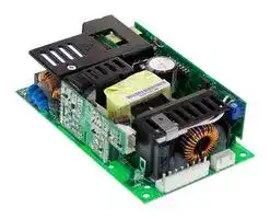
RPTG-160A
AC/DC Open Frame Power Supply (PSU), Medical, 3 Output, 145W @ 20.5CFM, 100 W, 90V AC to 264V AC
⚠️ Reference pricing provided. In case of supply shortages, we will connect you with our trusted procurement partners to ensure your project's continuity.
- Manufacturer: MEAN WELL
- Product type: AC / DC Open Frame Power Supplies
- No. of Outputs:3 Output; Power Rating (Covection Cooling):100W; Power Rating (Forced Cooling):145W @ 20.5CFM; Input Voltage VAC:90V AC to 264V AC; Power Supply Output Type:Adjust
- SVHC: No SVHC (25-Jun-2025)
- Product Range: RPTG-160 Series
- No. of Outputs: 3 Output
- Output Power Max: 98.6W
- Input Voltage VAC: 90V AC to 264V AC
- Input Voltage AC Max: 264V
- Input Voltage AC Min: 90V
- Power Supply Output Type: Adjustable, Fixed
- Output Current - Output 1: 9A
- Output Current - Output 2: 3.8A
- Output Current - Output 3: 600mA
- Output Current - Output 4: -
- Output Voltage - Output 1: 5VDC
- Output Voltage - Output 2: 12VDC
- Output Voltage - Output 3: -5VDC
- Output Voltage - Output 4: -
- Power Supply Applications: Medical
- Power Rating (Forced Cooling): 145W @ 20.5CFM
- Power Rating (Convection Cooling): 100W
| Delivery and price | |
|---|---|
| Units per pack | 50 |
| Price | 51.5 € |
| Current stock | 10+ |
| Lead time | 30 days |
Datasheet

**- RPT 160 series**

160W Triple Output Medical Type MEAN WELL ~~Ceee~~ e **e** ee ee

■

## **RPT G 160A**

## **G: With 5Vsb & no load power consumption < 0.75 W Blank: Basic function (without 5Vsb)**

## **SPECIFICATION**

|**MODEL**<br>**DC VOLTAGE**<br>**RATED CURRENT (20.5CFM)**<br>**RATED POWER (convection) Note.7**<br>**CURRENT RANGE (20.5CFM)**<br>**OUTPUT**<br>**VOLTAGE ADJ. RANGE**<br>**LINE REGULATION**<br>**LOAD REGULATION**<br>**SETUP, RISE TIME**<br>**HOLD UP TIME (Typ.)**<br>**VOLTAGE RANGE**<br>**Note.6**<br>**FREQUENCY RANGE**<br>**POWER FACTOR (Typ.)**<br>**EFFICIENCY (Typ.)**<br>**INPUT**<br>**INRUSH CURRENT (Typ.)**<br>**LEAKAGE CURRENT**<br>**Note.9**<br>**SAFETY STANDARDS**<br>**WORKING TEMP.**<br>**WORKING HUMIDITY**<br>**STORAGE TEMP., HUMIDITY**<br>**TEMP. COEFFICIENT**<br>**VIBRATION**<br>**OVERLOAD**<br>**OVER VOLTAGE**<br>**OVER TEMPERATURE**<br>**AC CURRENT (Typ.)**<br>1800ms, 30ms/230VAC           3500ms, 30ms/115VAC at full load<br>90 ~ 264VAC          127 ~ 370VDC<br>16ms/230VAC/115VAC at full load<br>47 ~ 63Hz<br>PF>0.93/230VAC          PF>0.98/115VAC at full load<br>1.8A/115VAC          0.9A/230VAC<br>COLD START 35A/115VAC          70A/230VAC<br>105 ~ 135% rated output power<br>Protection type : Hiccup mode, recovers automatically after fault condition is removed<br>Protection type : Shut down o/p voltage, re-power on to recover<br>CH1: 5.75 ~ 6.75V<br>TSW2: Shut down o/p voltage, re-power on to recover<br>TSW1:Shut down o/p voltage, recovers automatically after temperature goes down<br>ANSI/AAMI ES60601-1, TUV EN60601-1 approved<br>-20 ~ +70<br>(Refer to "Derating Curve")<br>℃<br>20 ~ 90% RH non-condensing<br>-40 ~ +85<br>, 10 ~ 95% RH<br>℃<br>±<br>℃<br>℃<br>0.03%/<br>(0 ~ 50<br>)<br>10 ~ 500Hz, 2G 10min./1cycle, 60min. each along X, Y, Z axes<br>**WITHSTAND VOLTAGE**<br>**ISOLATION RESISTANCE**<br>I/P-O/P:4KVAC     I/P-FG:2KVAC     O/P-FG:1.5KVAC<br>I/P-O/P, I/P-FG, O/P-FG:100M Ohms / 500VDC / 25<br>/ 70% RH<br>℃<br>**SAFETY &**<br>**EMC**<br>**(Note 4)**<br>**PROTECTION**<br>**ENVIRONMENT**<br>**CURRENT RANGE (convection)**<br>**RIPPLE & NOISE (max.) Note.2**<br>**RATED POWER (20.5CFM) Note.8**<br>**VOLTAGE TOLERANCE Note.3**<br>**POWER GOOD / POWER FAIL**<br>Power on: PS-ON = "Hi" or " > 2 ~ 5V" ;  Power off: PS-ON = "Low" or " < 0 ~ 0.5V"<br>500ms>PG>10ms          PF>1ms<br>**FUNCTION**<br>Compliance to EN55011 (CISPR11), EN55022 (CISPR22) Class B, EN61000-3-2,-3<br>**MTBF**<br>**DIMENSION**<br>**OTHERS**<br>Compliance to EN61000-4-2,3,4,5,6,8,11, EN55024, EN60601-1-2, EN61204-3, medical level, criteria A<br>191.4K hrs min.      MIL-HDBK-217F (25<br>)<br>℃<br>127*76.2*34.6mm (L*W*H)<br>**PACKING**<br>0.33Kg; 36pcs/12.9Kg/0.79CUFT<br>**NOTE**<br>℃<br>84%<br>CH1<br>CH1<br>CH1<br>CH1<br>**OUTPUT NUMBER**<br>**RPT**<br>**-160A**<br>□<br>5V<br>14A<br>0.6 ~ 9A<br>0.6 ~ 14A<br>14A<br>0.6 ~ 9A<br>0.6 ~ 14A<br>98.6W<br>145W<br>100mVp-p<br>CH1:5 ~ 5.5V<br>±2.0%<br>±0.5%<br>±1.5%<br>**RPT**<br>**-160B**<br>□<br>**RPT**<br>**-160C**<br>□<br>**RPT**<br>**-160D**<br>□<br>12V<br>CH2<br>CH2<br>CH2<br>CH2<br>-5V<br>CH3<br>CH3<br>CH3<br>CH3<br>12V<br>-12V<br>15V<br>12V<br>-15V<br>24V<br>5V<br>5V<br>5V<br>5.5A<br>0.2 ~ 3.8A<br>0.2 ~ 5.5A<br>5A<br>0.2 ~ 3.4A<br>0.2 ~ 5A<br>1A<br>0.1 ~ 0.6A<br>0.1 ~ 1A<br>1A<br>0.1 ~ 0.8A<br>0.1 ~ 1A<br>3.6A<br>5A<br>0.1 ~ 2.6A<br>0.2 ~ 2.6A<br>0.1 ~ 3.6A<br>0.2 ~ 5A<br>1A<br>1.2A<br>0.1 ~ 0.8A<br>0.15 ~ 1A<br>0.1 ~ 1A<br>0.15 ~ 1.2A<br>14A<br>11A<br>0.6 ~ 9A<br>0.3 ~ 8A<br>0.6 ~ 14A<br>0.3 ~ 11A<br>98.4W<br>146W<br>99W<br>98.2W<br>143W<br>147.8W<br>120mVp-p 120mVp-p 100mVp-p 120mVp-p 120mVp-p<br>150mVp-p<br>120mVp-p<br>150mVp-p<br>200mVp-p<br>100mVp-p<br>100mVp-p<br>±5.0%<br>-5,+7%<br>±5.0%<br>-4,+5%<br>±4.0%<br>±5.0%<br>±8.0%<br>+7,-5%<br>±1.0%<br>±1.0%<br>±1.0%<br>±1.0%<br>±1.0%<br>±1.0%<br>±1.0%<br>±1.0%<br>±3.0%<br>-5,+6%<br>±3.0%<br>-4,+5%<br>±3.0%<br>±3.0%<br>±8.0%<br>-3,+4%<br>±2.0%<br>±2.0%<br>±2.0%<br>±0.5%<br>±1.5%<br>±0.5%<br>±0.5%<br>±2.0%<br>±1.5%<br>84%<br>83%<br>83%<br>**5V STANDBY (G model)**<br>5VSB : 5V@0.6A without fan, 0.8A with fan 20.5CFM ; tolerance<br>2%, ripple : 50mVp-p(max.)<br>±<br>**PS-ON INPUT SIGNAL (G model)**<br>**EMC IMMUNITY**<br>**EMC EMISSION**<br>Earth leakage current < 200 A/264VAC , Touch current < 100 A/264VAC<br>μ<br>μ<br>**ISOLATION LEVEL**<br>Primary-Secondary: 2xMOPP, Primary-Earth:1xMOPP, Secondary-Earth:1xMOPP<br>1. All parameters NOT specially mentioned are measured at230VAC input, rated load and 25 _ of ambient temperature.<br>2. Ripple & noise are measured at20MHz of bandwidth by using a 12" twisted pair-wire terminated with a 0.1uf & 47uf parallel capacitor.<br>3. Tolerance<br>: includes set up tolerance, line regulation and load regulation.<br>4. The power supply is considered a component which will be installed into a final equipment. All the EMC tests are been executed by mounting the unit on<br>a 360mm*360mm metal plate with 1mm of thickness. The final equipment must be re-confirmed that it still meets EMC directives. For guidance on how to<br>perform these EMC tests, please refer to “EMI testing of component power supplies.” (as available on http:/Avww.meanwell.com)<br>5. HS1,HS2 & HS3 can not be shorted.<br>6. Derating may be needed under low input voltages. Please check the derating curve for more details.<br>7. The rated power includes 5Vsb@ 0.6A.<br>8. The rated power includes 5Vsb@ 0.8A.<br>9. Touch current was measured from primary input to DC output.|**MODEL**<br>**DC VOLTAGE**<br>**RATED CURRENT (20.5CFM)**<br>**RATED POWER (convection) Note.7**<br>**CURRENT RANGE (20.5CFM)**<br>**OUTPUT**<br>**VOLTAGE ADJ. RANGE**<br>**LINE REGULATION**<br>**LOAD REGULATION**<br>**SETUP, RISE TIME**<br>**HOLD UP TIME (Typ.)**<br>**VOLTAGE RANGE**<br>**Note.6**<br>**FREQUENCY RANGE**<br>**POWER FACTOR (Typ.)**<br>**EFFICIENCY (Typ.)**<br>**INPUT**<br>**INRUSH CURRENT (Typ.)**<br>**LEAKAGE CURRENT**<br>**Note.9**<br>**SAFETY STANDARDS**<br>**WORKING TEMP.**<br>**WORKING HUMIDITY**<br>**STORAGE TEMP., HUMIDITY**<br>**TEMP. COEFFICIENT**<br>**VIBRATION**<br>**OVERLOAD**<br>**OVER VOLTAGE**<br>**OVER TEMPERATURE**<br>**AC CURRENT (Typ.)**<br>1800ms, 30ms/230VAC           3500ms, 30ms/115VAC at full load<br>90 ~ 264VAC          127 ~ 370VDC<br>16ms/230VAC/115VAC at full load<br>47 ~ 63Hz<br>PF>0.93/230VAC          PF>0.98/115VAC at full load<br>1.8A/115VAC          0.9A/230VAC<br>COLD START 35A/115VAC          70A/230VAC<br>105 ~ 135% rated output power<br>Protection type : Hiccup mode, recovers automatically after fault condition is removed<br>Protection type : Shut down o/p voltage, re-power on to recover<br>CH1: 5.75 ~ 6.75V<br>TSW2: Shut down o/p voltage, re-power on to recover<br>TSW1:Shut down o/p voltage, recovers automatically after temperature goes down<br>ANSI/AAMI ES60601-1, TUV EN60601-1 approved<br>-20 ~ +70<br>(Refer to "Derating Curve")<br>℃<br>20 ~ 90% RH non-condensing<br>-40 ~ +85<br>, 10 ~ 95% RH<br>℃<br>±<br>℃<br>℃<br>0.03%/<br>(0 ~ 50<br>)<br>10 ~ 500Hz, 2G 10min./1cycle, 60min. each along X, Y, Z axes<br>**WITHSTAND VOLTAGE**<br>**ISOLATION RESISTANCE**<br>I/P-O/P:4KVAC     I/P-FG:2KVAC     O/P-FG:1.5KVAC<br>I/P-O/P, I/P-FG, O/P-FG:100M Ohms / 500VDC / 25<br>/ 70% RH<br>℃<br>**SAFETY &**<br>**EMC**<br>**(Note 4)**<br>**PROTECTION**<br>**ENVIRONMENT**<br>**CURRENT RANGE (convection)**<br>**RIPPLE & NOISE (max.) Note.2**<br>**RATED POWER (20.5CFM) Note.8**<br>**VOLTAGE TOLERANCE Note.3**<br>**POWER GOOD / POWER FAIL**<br>Power on: PS-ON = "Hi" or " > 2 ~ 5V" ;  Power off: PS-ON = "Low" or " < 0 ~ 0.5V"<br>500ms>PG>10ms          PF>1ms<br>**FUNCTION**<br>Compliance to EN55011 (CISPR11), EN55022 (CISPR22) Class B, EN61000-3-2,-3<br>**MTBF**<br>**DIMENSION**<br>**OTHERS**<br>Compliance to EN61000-4-2,3,4,5,6,8,11, EN55024, EN60601-1-2, EN61204-3, medical level, criteria A<br>191.4K hrs min.      MIL-HDBK-217F (25<br>)<br>℃<br>127*76.2*34.6mm (L*W*H)<br>**PACKING**<br>0.33Kg; 36pcs/12.9Kg/0.79CUFT<br>**NOTE**<br>℃<br>84%<br>CH1<br>CH1<br>CH1<br>CH1<br>**OUTPUT NUMBER**<br>**RPT**<br>**-160A**<br>□<br>5V<br>14A<br>0.6 ~ 9A<br>0.6 ~ 14A<br>14A<br>0.6 ~ 9A<br>0.6 ~ 14A<br>98.6W<br>145W<br>100mVp-p<br>CH1:5 ~ 5.5V<br>±2.0%<br>±0.5%<br>±1.5%<br>**RPT**<br>**-160B**<br>□<br>**RPT**<br>**-160C**<br>□<br>**RPT**<br>**-160D**<br>□<br>12V<br>CH2<br>CH2<br>CH2<br>CH2<br>-5V<br>CH3<br>CH3<br>CH3<br>CH3<br>12V<br>-12V<br>15V<br>12V<br>-15V<br>24V<br>5V<br>5V<br>5V<br>5.5A<br>0.2 ~ 3.8A<br>0.2 ~ 5.5A<br>5A<br>0.2 ~ 3.4A<br>0.2 ~ 5A<br>1A<br>0.1 ~ 0.6A<br>0.1 ~ 1A<br>1A<br>0.1 ~ 0.8A<br>0.1 ~ 1A<br>3.6A<br>5A<br>0.1 ~ 2.6A<br>0.2 ~ 2.6A<br>0.1 ~ 3.6A<br>0.2 ~ 5A<br>1A<br>1.2A<br>0.1 ~ 0.8A<br>0.15 ~ 1A<br>0.1 ~ 1A<br>0.15 ~ 1.2A<br>14A<br>11A<br>0.6 ~ 9A<br>0.3 ~ 8A<br>0.6 ~ 14A<br>0.3 ~ 11A<br>98.4W<br>146W<br>99W<br>98.2W<br>143W<br>147.8W<br>120mVp-p 120mVp-p 100mVp-p 120mVp-p 120mVp-p<br>150mVp-p<br>120mVp-p<br>150mVp-p<br>200mVp-p<br>100mVp-p<br>100mVp-p<br>±5.0%<br>-5,+7%<br>±5.0%<br>-4,+5%<br>±4.0%<br>±5.0%<br>±8.0%<br>+7,-5%<br>±1.0%<br>±1.0%<br>±1.0%<br>±1.0%<br>±1.0%<br>±1.0%<br>±1.0%<br>±1.0%<br>±3.0%<br>-5,+6%<br>±3.0%<br>-4,+5%<br>±3.0%<br>±3.0%<br>±8.0%<br>-3,+4%<br>±2.0%<br>±2.0%<br>±2.0%<br>±0.5%<br>±1.5%<br>±0.5%<br>±0.5%<br>±2.0%<br>±1.5%<br>84%<br>83%<br>83%<br>**5V STANDBY (G model)**<br>5VSB : 5V@0.6A without fan, 0.8A with fan 20.5CFM ; tolerance<br>2%, ripple : 50mVp-p(max.)<br>±<br>**PS-ON INPUT SIGNAL (G model)**<br>**EMC IMMUNITY**<br>**EMC EMISSION**<br>Earth leakage current < 200 A/264VAC , Touch current < 100 A/264VAC<br>μ<br>μ<br>**ISOLATION LEVEL**<br>Primary-Secondary: 2xMOPP, Primary-Earth:1xMOPP, Secondary-Earth:1xMOPP<br>1. All parameters NOT specially mentioned are measured at230VAC input, rated load and 25 _ of ambient temperature.<br>2. Ripple & noise are measured at20MHz of bandwidth by using a 12" twisted pair-wire terminated with a 0.1uf & 47uf parallel capacitor.<br>3. Tolerance<br>: includes set up tolerance, line regulation and load regulation.<br>4. The power supply is considered a component which will be installed into a final equipment. All the EMC tests are been executed by mounting the unit on<br>a 360mm*360mm metal plate with 1mm of thickness. The final equipment must be re-confirmed that it still meets EMC directives. For guidance on how to<br>perform these EMC tests, please refer to “EMI testing of component power supplies.” (as available on http:/Avww.meanwell.com)<br>5. HS1,HS2 & HS3 can not be shorted.<br>6. Derating may be needed under low input voltages. Please check the derating curve for more details.<br>7. The rated power includes 5Vsb@ 0.6A.<br>8. The rated power includes 5Vsb@ 0.8A.<br>9. Touch current was measured from primary input to DC output.|**RPT**<br>**-160A**<br>□|**RPT**<br>**-160A**<br>□|**RPT**<br>**-160A**<br>□|**RPT**<br>**-160B**<br>□|**RPT**<br>**-160B**<br>□|**RPT**<br>**-160B**<br>□|**RPT**<br>**-160C**<br>□|**RPT**<br>**-160C**<br>□|**RPT**<br>**-160C**<br>□|**RPT**<br>**-160D**<br>□|**RPT**<br>**-160D**<br>□|**RPT**<br>**-160D**<br>□|
|---|---|---|---|---|---|---|---|---|---|---|---|---|---|
||**OUTPUT NUMBER**|CH1|CH2|CH3|CH1|CH2|CH3|CH1|CH2|CH3|CH1|CH2|CH3|
||**DC VOLTAGE**|5V|12V|-5V|5V|12V|-12V|5V|15V|-15V|5V|12V|24V|
||**RATED CURRENT (20.5CFM)**|14A|5.5A|1A|14A|5A|1A|14A|3.6A|1A|11A|5A|1.2A|
||**CURRENT RANGE (convection)**|0.6 ~ 9A|0.2 ~ 3.8A|0.1 ~ 0.6A|0.6 ~ 9A|0.2 ~ 3.4A|0.1 ~ 0.8A|0.6 ~ 9A|0.1 ~ 2.6A|0.1 ~ 0.8A|0.3 ~ 8A|0.2 ~ 2.6A|0.15 ~ 1A|
||**CURRENT RANGE (20.5CFM)**|0.6 ~ 14A|0.2 ~ 5.5A|0.1 ~ 1A|0.6 ~ 14A|0.2 ~ 5A|0.1 ~ 1A|0.6 ~ 14A|0.1 ~ 3.6A|0.1 ~ 1A|0.3 ~ 11A|0.2 ~ 5A|0.15 ~ 1.2A|
||**RATED POWER (convection) Note.7**|98.6W|||98.4W|||99W|||98.2W|||
||**RATED POWER (20.5CFM) Note.8**|145W|||146W|||143W|||147.8W|||
||**RIPPLE & NOISE (max.) Note.2**|100mVp-p|120mVp-p|120mVp-p|100mVp-p|120mVp-p|120mVp-p|100mVp-p|150mVp-p|150mVp-p|100mVp-p|120mVp-p|200mVp-p|
||**VOLTAGE ADJ. RANGE**|CH1:5 ~ 5.5V||||||||||||
||**VOLTAGE TOLERANCE Note.3**|±2.0%|±5.0%|-5,+7%|±2.0%|±5.0%|-4,+5%|±2.0%|±4.0%|±8.0%|±2.0%|±5.0%|+7,-5%|
||**LINE REGULATION**|±0.5%|±1.0%|±1.0%|±0.5%|±1.0%|±1.0%|±0.5%|±1.0%|±1.0%|±0.5%|±1.0%|±1.0%|
||**LOAD REGULATION**|±1.5%|±3.0%|-5,+6%|±1.5%|±3.0%|-4,+5%|±2.0%|±3.0%|±8.0%|±1.5%|±3.0%|-3,+4%|
||**SETUP, RISE TIME**|1800ms, 30ms/230VAC           3500ms, 30ms/115VAC at full load||||||||||||
||**HOLD UP TIME (Typ.)**|16ms/230VAC/115VAC at full load||||||||||||
||**VOLTAGE RANGE**<br>**Note.6**|90 ~ 264VAC          127 ~ 370VDC||||||||||||
||**FREQUENCY RANGE**|47 ~ 63Hz||||||||||||
||**POWER FACTOR (Typ.)**|PF>0.93/230VAC          PF>0.98/115VAC at full load||||||||||||
||**EFFICIENCY (Typ.)**|84%|||84%|||83%|||83%|||
||**AC CURRENT (Typ.)**|1.8A/115VAC          0.9A/230VAC||||||||||||
||**INRUSH CURRENT (Typ.)**|COLD START 35A/115VAC          70A/230VAC||||||||||||
||**LEAKAGE CURRENT**<br>**Note.9**|Earth leakage current < 200 A/264VAC , Touch current < 100 A/264VAC<br>μ<br>μ||||||||||||
||**OVERLOAD**|105 ~ 135% rated output power<br>Protection type : Hiccup mode, recovers automatically after fault condition is removed||||||||||||
||**OVER VOLTAGE**|Protection type : Shut down o/p voltage, re-power on to recover<br>CH1: 5.75 ~ 6.75V||||||||||||
||**OVER TEMPERATURE**|TSW2: Shut down o/p voltage, re-power on to recover<br>TSW1:Shut down o/p voltage, recovers automatically after temperature goes down||||||||||||
||**5V STANDBY (G model)**|5VSB : 5V@0.6A without fan, 0.8A with fan 20.5CFM ; tolerance<br>2%, ripple : 50mVp-p(max.)<br>±||||||||||||
||**PS-ON INPUT SIGNAL (G model)**|Power on: PS-ON = "Hi" or " > 2 ~ 5V" ;  Power off: PS-ON = "Low" or " < 0 ~ 0.5V"||||||||||||
||**POWER GOOD / POWER FAIL**|500ms>PG>10ms          PF>1ms||||||||||||
||**WORKING TEMP.**|-20 ~ +70<br>(Refer to "Derating Curve")<br>℃||||||||||||
||**WORKING HUMIDITY**|20 ~ 90% RH non-condensing||||||||||||
||**STORAGE TEMP., HUMIDITY**|-40 ~ +85<br>, 10 ~ 95% RH<br>℃||||||||||||
||**TEMP. COEFFICIENT**|±<br>℃<br>℃<br>0.03%/<br>(0 ~ 50<br>)||||||||||||
||**VIBRATION**|10 ~ 500Hz, 2G 10min./1cycle, 60min. each along X, Y, Z axes||||||||||||
||**SAFETY STANDARDS**|ANSI/AAMI ES60601-1, TUV EN60601-1 approved||||||||||||
||**WITHSTAND VOLTAGE**<br>**ISOLATION LEVEL**|I/P-O/P:4KVAC     I/P-FG:2KVAC     O/P-FG:1.5KVAC<br>Primary-Secondary: 2xMOPP, Primary-Earth:1xMOPP, Secondary-Earth:1xMOPP||||||||||||
||**ISOLATION RESISTANCE**|I/P-O/P, I/P-FG, O/P-FG:100M Ohms / 500VDC / 25<br>/ 70% RH<br>℃||||||||||||
||**EMC EMISSION**|Compliance to EN55011 (CISPR11), EN55022 (CISPR22) Class B, EN61000-3-2,-3||||||||||||
||**EMC IMMUNITY**|Compliance to EN61000-4-2,3,4,5,6,8,11, EN55024, EN60601-1-2, EN61204-3, medical level, criteria A||||||||||||
||**MTBF**|191.4K hrs min.      MIL-HDBK-217F (25<br>)<br>℃||||||||||||
||**DIMENSION**|127*76.2*34.6mm (L*W*H)||||||||||||
||**PACKING**<br>0.33Kg; 36pcs/12.9Kg/0.79CUFT<br>℃<br>1. All parameters NOT specially mentioned are measured at230VAC input, rated load and 25 _ of ambient temperature.<br>2. Ripple & noise are measured at20MHz of bandwidth by using a 12" twisted pair-wire terminated with a 0.1uf & 47uf parallel capacitor.<br>3. Tolerance<br>: includes set up tolerance, line regulation and load regulation.<br>4. The power supply is considered a component which will be installed into a final equipment. All the EMC tests are been executed by mounting the unit on<br>a 360mm*360mm metal plate with 1mm of thickness. The final equipment must be re-confirmed that it still meets EMC directives. For guidance on how to<br>perform these EMC tests, please refer to “EMI testing of component power supplies.” (as available on http:/Avww.meanwell.com)<br>5. HS1,HS2 & HS3 can not be shorted.<br>6. Derating may be needed under low input voltages. Please check the derating curve for more details.<br>7. The rated power includes 5Vsb@ 0.6A.<br>8. The rated power includes 5Vsb@ 0.8A.<br>9. Touch current was measured from primary input to DC output.|||||||||||||


_File Name:RPT-160-SPEC 2015_ - _08-06_

## 160W Triple Output Medical Type

## **- RPT 160 series**

**==> picture [511 x 668] intentionally omitted <==**

**----- Start of picture text -----**<br>
Mechanical Specification Unit:mm<br>FAN<br>AC Input Connector (CN1) : JST B3P-VH or equivalent<br>20.5CFM min. Pin No. Assignment Mating Housing Terminal<br>1 AC/L<br>JST VHR JST SVH-21T-P1.1<br>2 No Pin<br>M1 SVR1 3 AC/N or equivalent or equivalent<br>HS1 CN3<br>12 DC Output Connector (CN2) : JST B8P-VH or equivalent<br>Pin No. Assignment Mating Housing Terminal<br>1<br>2 1,2,3,4 COM<br>FS1 HS2 34 5,6 CH1 JST VHR JST SVH-21T-P1.1<br>1 5 7 CH2 or equivalent or equivalent<br>CN1 23 HS3 67 8 CH3<br>FS2 CN2 8 CN901 Power Good Connector(CN3):JST B2B-XH or equivalent<br>M2 CN901 LED Pin No. Status Mating Housing Terminal<br>1 2 3 4 1 PG JST XHP JST SXH-001T-P0.6<br>5 117 2 GND or equivalent or equivalent<br>127 5VSB Connector(CN901) : JST B-XH or equivalent<br>PS/ON Pin No. Assignment Mating Housing Terminal<br>1 PS/ON<br>5mA(max.) 2,4 GND JST XHP JST SXH-001T<br>or equivalent or equivalent<br>3 5VSB<br>GND<br>1.HS1,HS2,HS3 can not be shorted<br>2.M1 and M2 are Safety ground and should all be grounded.<br>Block Diagram<br>+5VSB fosc :100KHz<br>DETECTION<br>CIRCUIT<br>POWER SWITCHING RECTIFIERS& +5VSB<br>PWM CONTROL FILTER<br>RECTIFIERS V3<br>&<br>FILTER<br>RECTIFIERS +V2<br>&<br>FILTER<br>I/P FILTEREMI RECTIFIERSPFC& SWITCHINGPOWER RECTIFIERSFILTER& +V1COM<br>PG PG<br>DETECTION<br>FG O.L.P. CONTROL CIRCUIT<br>O.V.P.<br>PS/ON PS/ON<br>CONTROL<br>Derating Curve Output Derating VS Input Voltage<br>100<br>100<br>With FAN<br>90<br>80<br>80<br>60 70<br>Without FAN 60<br>40<br>50<br>20<br>40<br>-20 0 10 20 30 40 50 60 70 (HORIZONTAL) 90 95 100 115 120 140 160 180 200 220 240 264<br>AMBIENT TEMPERATURE ( ℃ ) INPUT VOLTAGE (VAC) 60Hz<br>4-<br>ψ<br>3.5<br>LOAD (%) LOAD (%)<br>76.2 66.2<br>34.6<br>3 max.<br>5cm<br>5<br>**----- End of picture text -----**<br>


_File Name:RPT-160-SPEC 2015_ - _08-06_
Updated at June 10, 2026
About Novapart
Novapart is a B2B electronic component broker specialising in stock shortages and cost reduction. We source hard-to-find parts and identify compliant alternatives across a catalogue of 410,000+ components from 500+ manufacturers.
Learn more →Stock Shortage Specialist
When a component is unavailable, discontinued or has an unacceptable lead time, we tap into our network of vetted European and Asian distributors to source what you need — without compromising on quality or traceability.
Request a quote →Compliant Alternatives
We identify pin-to-pin, electrically equivalent substitutes that meet the same certifications (RoHS, AEC-Q100, REACH) as your original specification — validated against datasheets, not just part numbers. Often at a lower cost.
BOM Analysis service →